Article

Evaluation of the Specific Capacitance of High-Entropy Oxide-Based Electrode Materials in View of Their Use for Water Desalination via Capacitive Method

1
Dipartimento di Ingegneria Civile, dell’Energia, dell’Ambiente e dei Materiali (DICEAM), Università “Mediterranea”, Loc. Feo di Vito, 89122 Reggio Calabria, Italy
2
National Reference Center for Electrochemical Energy Storage (GISEL), Consorzio Interuniversitario Nazionale per la Scienza e Tecnologia dei Materiali (INSTM), 50121 Firenze, Italy
3
Parque Científico y Tecnológico de Bizkaia, TECNALIA, Basque Research and Technology Alliance (BRTA), Astondo Bidea, Edif. 700, Derio, 48160 Bizkaia, Spain
*
Author to whom correspondence should be addressed.
Appl. Sci. 2023, 13(2), 721; https://doi.org/10.3390/app13020721
Submission received: 14 December 2022 / Revised: 29 December 2022 / Accepted: 30 December 2022 / Published: 4 January 2023
(This article belongs to the Special Issue High-Entropy Materials and Their Applications)

Abstract

:
Water pollution and scarcity are serious concerns for the growing world population. To meet the ever-pressing demand of fresh water, a variety of desalting techniques of seawater have been developed. Due to its environmental friendliness, high efficiency, easy regeneration of the electrodes, ambient operating pressure, and low operating potential suitable for the use in remote areas, the capacitive deionization (CDI) method is one of the most sustainable among them. This work focuses on the preparation of high-entropy oxides (HEOs) and carbon/HEO composites and the evaluation of their specific capacitance in view of their possible use as CDI electrode materials. CrMnFeCoNi-HEO, having spinel structure (sHEO), is obtained in the form of nanoparticles (NPs) and nanofibers (NFs) by the sol–gel method and electrospinning, respectively. Composite NFs with embedded sHEO NPs or MgCoNiCuZn-HEO NPs with rock-salt structure (rHEO) are also produced. In the 5–100 mV s−1 scan rate range, the specific capacitance improves in the order C/rHEO NFs (8–32 F g−1) ≅ sHEO NPs (9–32 F g−1) < sHEO NFs (8–43 F g−1) < C/sHEO NFs (12–66 F g−1). The highest capacitance is obtained when the beneficial contributions of the carbon matrix and smaller-sized HEO NPs are synergistically coupled.

1. Introduction

The availability of freshwater resources for the survival of humanity on the planet has become a critical global issue with the increase of world population and rapid industrial development, as well as the increasingly serious water pollution and climate changes. At present, nearly 750 million people worldwide have limited access to clean drinking water, and this number of people is forecasted to rise in the upcoming years. The United Nations World Water Development report (2021) stated that the world would tackle a 40% shortage of freshwater resources by 2030 unless the water resource management is improved [1]. In this scenario, considering that seawater represents approximately 97% of the total available water resources on the Earth, the desalination process becomes one of the most promising ways for many societies to secure fresh water and to face global water scarcity [2]. Presently, reverse osmosis (RO) is the most widely adopted water desalination technique, with the largest capacity installed and operating in the world [3]. However, since it operates under high pressures (50–70 bar), generates large amounts of brine containing chemicals, and greatly consumes electricity, it has a significant impact on the environment and is not suitable for use in remote areas [3]. Several potential alternative desalination techniques have been developed to address these issues. An in-depth discussion on the benefits they offer over conventional RO and the challenges faced by these emerging techniques to become competitive with it can be found in ref. [3]. Among them, capacitive deionization (CDI) appears to be one of the most appealing because of the easy regeneration of the electrodes, operation under ambient temperatures, ambient pressures, and low voltage (0.8–2.0 V), and suitability for remote areas [4,5,6].
CDI is based on a complementary approach with respect to RO: it removes salt from water rather than water from salt [3]. Salt ions are electro-adsorbed inside porous electrodes under the action of the small applied voltage, which generates an electrical double-layer (EDL) on their surface [7,8]. The electrodes are easily regenerated by reversing, reducing, or short-circuiting the voltage of the cell [9]. Moreover, during the discharge, up to 83% of energy stored in the EDL can be recovered [3] and reused, with a reduction of the energy consumption of the process [5,6]. However, at the current stage of development, CDI is competitive with respect to RO only in the treatment of brackish water (salinity < 10 g L−1), with an electrical energy consumption below 1 versus 3–4 kWh m−3 potable water [10,11]. Conversely, in the desalination of seawater having a higher salinity (37 g L−1), CDI is not yet a mature technology for commercialization, as its energy consumption is by far higher than RO [3,11,12]. For a comparison based on a theoretical study between the energetic performance of CDI and RO as a function of feed salinity, water recovery, salt rejection, and average water flux, see ref. [11]. Another relevant aspect is the economic feasibility of CDI. It depends critically on the reduction of material costs through the increase in their life [12]. Possessing suitable properties for electro-sorption [13,14,15,16], porous carbons (such as activated carbons [17], graphene [18], carbon aerogels [19], carbon nanotubes [20], carbon nanofibers [21], and combinations of them [22,23]) are to date the most used electrode materials. Nevertheless, modifying or replacing them could be the key to improving CDI performance [3]. In fact, there are many studies in which their surface is functionalized to increase their wettability and provide additional adsorption sites [24]. Moreover, the addition of metal sulfide or oxides is another strategy to enhance the desalination performance of these carbon-based CDI electrodes by a charge transfer mechanism [3,9,25]. However, in spite of their good CDI performance, carbon-based materials often suffer from some shortcomings, such as co-ion expulsion effect, poor wettability, oxidation of the anode, and limited salt adsorption capacity, which heavily impact on the desalination capacity and stability of electrodes, as well as complexity and high cost of the fabrication process [26]. Therefore, the development of new highly performing advanced materials is crucial for the commercial application of the CDI technology.
Recently, high-entropy oxides (HEOs), a new type of oxides that combine five or more metals in an equiatomic or nearly equiatomic ratio, have attracted great interest due to their unique structure and their novel, and often unexpected, functional properties. They are based on the concept of high configurational entropy (≥1.5 R, where R is the universal gas constant) that stabilizes their structure into a single-crystal phase. HEOs exhibit extraordinary stability and electrochemical behavior which distinguish them from ordinary low-entropy metal oxides [27,28]. HEOs have been extensively evaluated as materials for environmental and energy applications, particularly in the fields of catalysis and energy conversion and storage [29,30].
This work reports the preparation of HEO and carbon/HEO composites and their characterization, focusing, for the first time, on the evaluation of their specific capacitance to explore the possibility of using them as CDI electrode materials since, generally, materials possessing superior capacitive performance exhibit better electro-sorption properties [18,22]. Spinel-structured CrMnFeCoNi-HEO NPs and NFs are investigated to clarify the effect of the HEO size and morphology. To study the influence of the oxide phase and the HEO-hosting C matrix, C/CrMnFeCoNi-HEO and C/MgCoNiCuZn-HEO composite NFs are also investigated. The electrode materials are prepared following two synthesis pathways (sol–gel or electrospinning, followed by heating treatment), which have already been proven to allow the formation of single-phase HEOs at temperatures that limit both the effects of sintering on the size of the HEO NPs and the environmental impact of the production process [29,31] with respect to the solid-state reaction most frequently utilised to prepare the HEOs [32,33,34,35].

2. Experimental

2.1. Materials and Synthesis Routes

Chromium (III) acetate hydroxide, Cr3(OH)2(CH3COO)7 (purity: 98%; CAS No. 39430-51-8, Sigma Aldrich, St. Louis, MO, USA), manganese(II) acetate tetrahydrate, Mn(CH3COO)2·4H2O (purity: 99%; CAS No. 6156-78-1, Sigma Aldrich), iron (II) acetate, Fe(CH3COO)2 (purity 95%; CAS No. 3094-87-9 Sigma Aldrich), cobalt (II) acetate tetrahydrate, Co(CH3COO)2·4H2O (purity: 99%; CAS No. 6147-53-1, Sigma Aldrich), and nickel (II) acetate tetrahydrate, Ni(CH3COO)2·4H2O (purity: 98%; CAS No. 6018-89-9, Sigma Aldrich) are utilized as precursors for the preparation of CrMnFeCoNi-HEO (sHEO) in the form of nanoparticles (NPs) and nanofibers (NFs).
sHEO NPs are produced by classical sol–gel method (SG), as already described in detail [31]. Citric acid monohydrate, HOC(COOH)(CH2COOH)2·H2O (purity: 98%; CAS No. 5949-29-1, Sigma Aldrich) is used as a complexing agent. Stoichiometric amounts of Cr, Mn, Fe, Co, and Ni are dissolved in water (30 g), one at a time; then, citric acid (3.5 g) is added under continuous stirring for 1 h at 90 °C. After drying at 80 °C overnight, the as-formed gel is calcined in static air at 350 °C for 2 h, 500 °C for 2 h, 800 °C for 2 h, and 900 °C for 2 h.
sHEO NFs are produced by electrospinning (ES), following the procedure illustrated in detail elsewhere [31]. Polyacrylonitrile (PAN), (C3H3N)n (average molecular weight: 150,000 g mol−1; purity: 99.9%; CAS No. 25014-41-9, Sigma Aldrich), and N,N-dimethylformamide (DMF), HCON(CH3)2 (anhydrous: 99.8%; CAS No. 68-12-2, Sigma Aldrich) are used for the preparation of the polymer/solvent solution. After complete dissolution of 7.1 wt% PAN in DMF, the five metallic salts, containing stoichiometric amounts of Cr, Mn, Fe, Co, and Ni, are added, one at a time, to the solution under continuous stirring. The total amount of metals is 38.5 wt% relative to PAN. After loading into a 20 mL syringe equipped with a 40 mm long 0.8 mm gauge stainless steel needle, the homogeneous solution, fed at 23.5 µL min−1 rate, is electrospun by using a CH-01 Electro-spinner 2.0 (Linari Engineering s.r.l.). ES is carried out at 25 ± 1 °C and 40–45% relative air humidity under a DC voltage of 15 kV applied between needle and the 15 cm distant grounded collector. After drying overnight and peeling from the collector, the as-spun membrane is calcined at 700 °C for 2 h and 900 °C for 2 h in static air.
C/sHEO composite NFs are obtained from the same spinnable solution and ES conditions as sHEO NFs by a different thermal treatment, namely stabilization in air at 225 °C for 2 h [36] and subsequent carbonization in inert atmosphere at 700 °C for 2 h and 900 °C for 2 h.
Magnesium (II) acetate tetrahydrate, Mg(CH3COO)2·4H2O (purity: 98%; CAS No. 16674-78-5, Sigma Aldrich), cobalt (II) acetate tetrahydrate, Co(CH3COO)2·4H2O (purity: 99%; CAS No. 6147-53-1, Sigma Aldrich), nickel (II) acetate tetrahydrate, Ni(CH3COO)2·4H2O (purity: 98%; CAS No. 6018-89-9, Sigma Aldrich), copper (II) acetate, Cu(CH3COO)2, (purity: 98%; CAS No. 142-71-2, Sigma Aldrich), and zinc (II) acetate dihydrate, Zn(CH3COO)2·2H2O (purity: 98%; CAS No. 5970-45-6, Fischer Scientific, Hampton, NH, USA) are utilized as precursors for the preparation of C/MgCoNiCuZn-HEO composite NFs by following the same procedure as for C/CrMnFeCoNi-HEO NFs.
It is worthwhile to note that both preparation methods selected here (SG and ES) to obtain HEOs from the precursors require very short heating treatments (only 4 h vs. 12–24 h [32,33,34,35]) and lower temperatures (900 °C vs. 1000–1300 °C [32,33,34,35]) compared with the solid-state reaction most frequently utilized to prepare the HEOs [32,33,34,35]. In addition, the latter technique is not suitable for the synthesis of C/HEO composites.

2.2. Structural and Morphological Characterization

The physicochemical properties of HEO-based CDI electrode materials are investigated by scanning electron microscopy (SEM), transmission electron microscopy (TEM), x-ray diffraction (XRD), and micro-Raman spectroscopy (MRS). Their texture and morphology are studied using a Phenom Pro-X scanning electron microscope. The microscope is equipped with an energy-dispersive X-ray (EDX) spectrometer that allows for elemental quantification. TEM images are recorded with a FEI Talos F200S scanning/transmission electron microscope, operated at 200 kV. The oxide phase(s) formed is investigated by a Bruker D2 Phaser diffractometer, equipped with a Ni-filtered Cu-Kα radiation source. The diffraction peaks are identified from the JCPDS database of reference compounds. The crystallinity of the HEO is investigated by a NTMDT NTEGRA Spectra SPM spectrometer, equipped with MS3504i 350 mm monochromator and ANDOR Idus CCD. Raman scattering excited by a solid-state laser, operating at 532 nm and attenuated through a neutral filter in order to have a power of ~250 μW on the sample surface, is measured in reflection mode, using a 100× objective (Mitutoyo, NA = 0.70) to collect the scattered light from the sample surface. An optical grating (600 lines/mm) disperses the acquired signal, finally detected by the cooled CCD.

2.3. Electrochemical Characterization

2.3.1. Preparation of HEO-Based Working Electrodes

The working electrodes are prepared by using the as-produced sHEO NPs, sHEO NFs, C/sHEO NFs, and C/rHEO NFs as active materials. The active material is mixed (mass ratio 9:1) with polyvinyl alcohol (PVA, (C2H4O)x, Tecnalia, Bizkaia, Spain) and dissolved in ethanol, (C2H5OH). The resulting mixture is ultrasonicated for at least 8 h until a homogeneous slurry is obtained. A graphite sheet (Mersen Ibérica) acts as current collector and as support to deposit the slurry. After drying in an oven at 60 °C to remove the organic solvents, a plane electrode is obtained. Electrodes of 2 cm2 area are used for electrochemical tests.

2.3.2. Electrochemical Capacitive Measurements

The formation of the EDL and electrochemical capacitive performance are evaluated by cyclic voltammetry (CV) technique. An AUTOLAB PG-STAT128N potentiostat is used to carry out CV measurements at room temperature. Measurements are performed in 0.1 mol L−1 NaCl solution using a conventional three-electrode configuration. The HEO-based electrode, a graphite sheet, and a standard Ag/AgCl electrode act as working electrode, counter electrode, and reference electrode, respectively. Current–voltage curves are recorded with sweep rates from 5 to 100 mVs−1 in the potential range from −1 to 0.2 V. The specific capacitance C (F g−1) of the electrode is calculated from the CV curves as:
C = 1 m v E 1 E 2 I d V V
where m (g) is the dry mass of the materials in the electrode, v (V s−1) is the potential scan rate, I (A) is the response current, V (V) is the potential, and E1E2 (V) indicates the potential window explored.

3. Results and Discussion

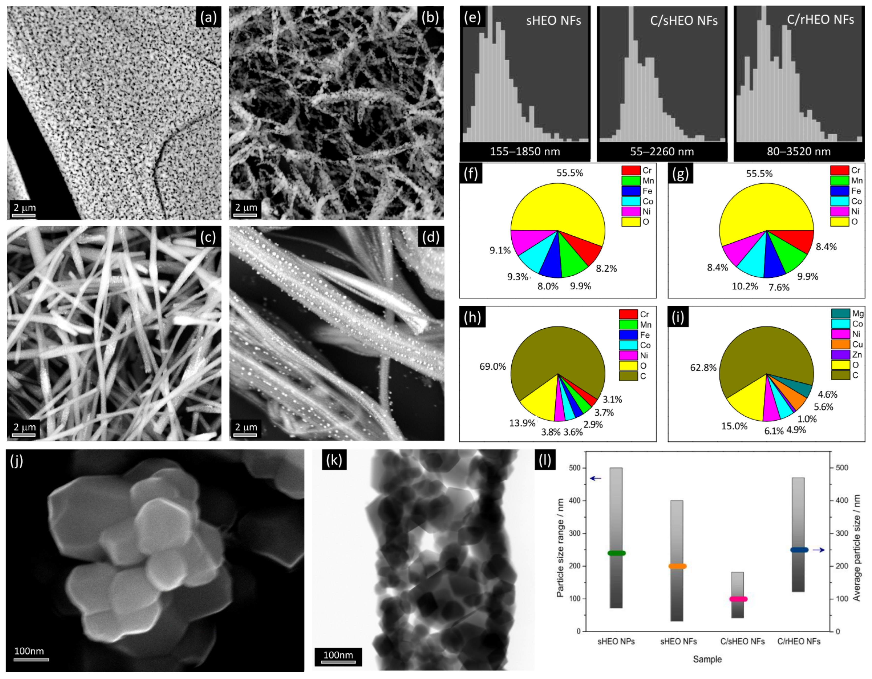
3.1. Morphology and Elemental Composition

3.1.1. Pure-HEO NPs and NFs

Figure 1 shows the main results of the SEM and TEM analyses. CrMnFeCoNi-HEO prepared by SG consists of aggregates of NPs (Figure 1a); TEM analysis reveals that NPs exhibit rounded/polyhedral shapes (Figure 1j) and sizes distributed in the range of 70–500 nm, with an average value of 240 nm (Figure 1l). The electrospun CrMnFeCoNi-HEO NFs are featured by a porous architecture (Figure 1b), as frequently observed for electrospun low-entropy oxides (LEOs) [37,38], as well as for HEO NFs with different composition [29,31]. The distribution of the NF diameters (Figure 1e) is centred at 0.66 μm. TEM analysis shows that the NFs are built up by interconnected NPs with similar shapes as those obtained by SG method (Figure 1k). The sizes of the NPs forming the fibres vary between 30 and 400 nm, i.e., in a narrower range with respect to those prepared by the SG method (Figure 1l); in addition, the average NP size is smaller (200 vs. 240 nm). The results of the compositional analysis by SEM/EDX (Figure 1f,g) confirm the removal of all organic components during calcination and prove the formation of oxide NPs and NFs based on the nearly equimolar combination of Cr, Mn, Fe, Co, and Ni.

3.1.2. C/HEO Composite NFs

C/CrMnFeCoNi-HEO composite NFs consist of carbon NFs with embedded oxide NPs (Figure 1c). The diameters of these NFs are distributed over a slightly wider range compared with those of CrMnFeCoNi-HEO NFs (Figure 1e); in addition, on average, composite NFs are thicker than pure HEO NFs (0.79 vs. 0.66 μm). As previously shown, both in the case of common LEOs [39,40] and HEOs with different composition [31], the host C matrix limits the development of the oxide grains and prevents their agglomeration. As a result, the CrMnFeCoNi-HEO NPs incorporated in the C NFs have sizes distributed in a narrower range (40–180 nm) and, on average, are smaller compared with those forming pure HEO NFs (110 vs. 200 nm). The results of the compositional analysis by SEM/EDX (Figure 1h) provide evidence that the C-embedded HEO NPs contain a nearly equimolar combination of Cr, Mn, Fe, Co, and Ni.
In the C/MgCoNiCuZn-HEO NFs (Figure 1d), the HEO partly protrudes out of the C NFs, as previously observed in the case of C/Ge/GeO2 electrospun NFs [40]. This is likely the effect of the outward diffusion of the five metals occurring during the carbonization at 700 and 900 °C [40]. Out of the fiber body, the MgCoNiCuZn clusters coalesce, giving rise to particles with a broad size distribution (120–470 nm) and, on average, larger size (250 nm) compared with C-embedded CrMnFeCoNi-HEO NPs. C/MgCoNiCuZn-HEO NFs have diameters distributed over a wider range with respect to both C/CrMnFeCoNi-HEO NFs (Figure 1e) and MgCoNiCuZn-HEO NFs, the subject of a previous study [29]. Analogously, the diameter distribution is centered at a higher value (1.23 μm) compared with both MgCoNiCuZn-HEO NFs (0.72 μm [29]) and C/CrMnFeCoNi-HEO NFs (0.79 μm).

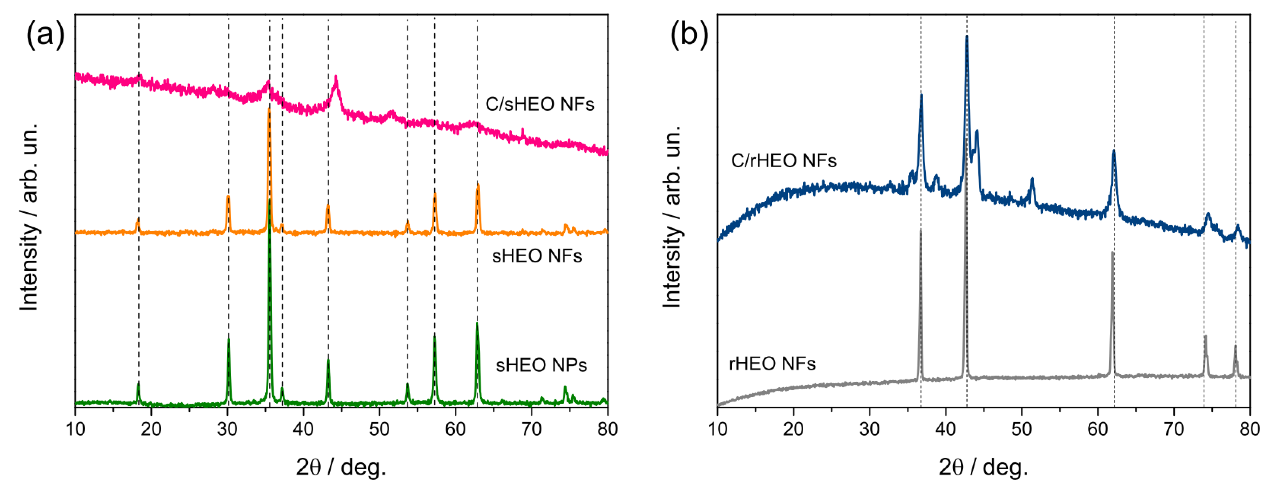
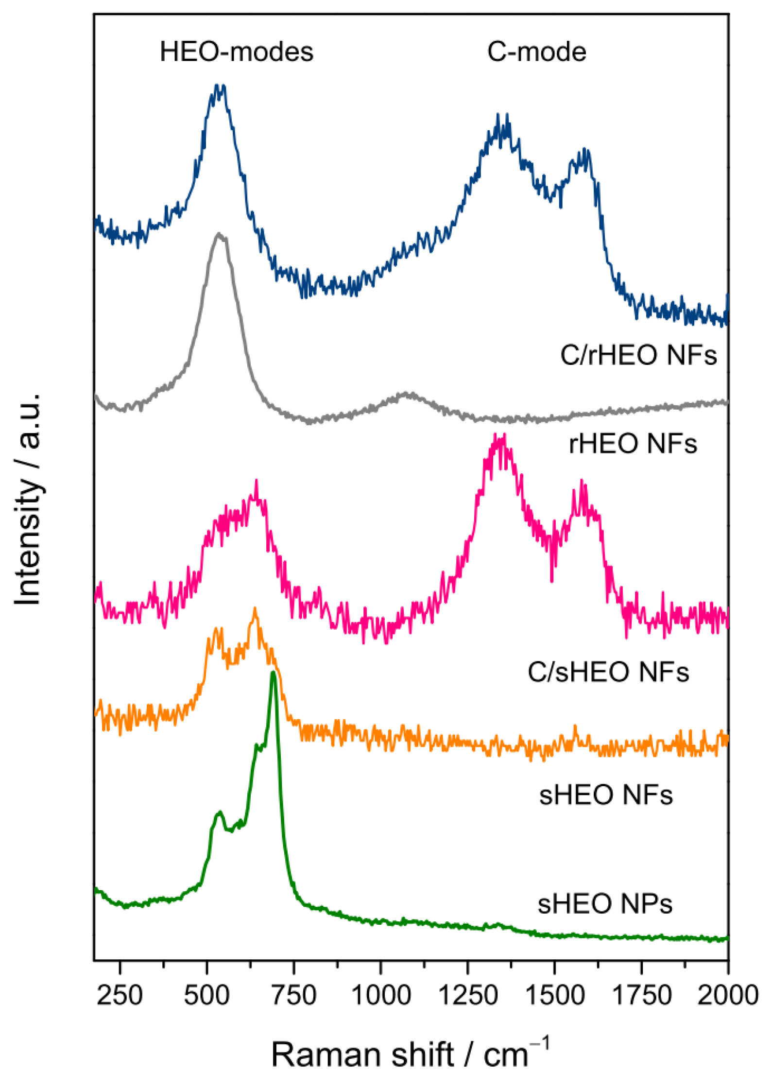
3.2. Phase of the Oxide

Figure 2 displays the results of the XRD analysis. In the diffractograms of CrMnFeCoNi-HEO NPs and NFs (Figure 2a), only the reflections from the (111), (220), (331), (222), (400), (422), (511), (440), (620), (533), and (622) planes of the face-centered cubic (fcc) spinel structure (JCPDS no. 22-1084) [41,42,43] are detected. This proves that (Cr0.2Mn0.2Fe0.2Co0.2Ni0.2)3O4 exclusively forms. The mean sizes of the sHEO crystallites, calculated through Scherrer’s equation from the strongest reflection, are 30.1 and 23.6 nm for NPs and NFs, respectively.
In the XRD pattern of C/CrMnFeCoNi-HEO NFs (Figure 2a), the peaks arising from the reflections from the spinel lattice planes are much broader. This finding points to smaller size and/or lower crystallinity of the C-embedded sHEO NPs. Moreover, two extra-peaks are clearly visible (at 44.3° and 51.6°), which hints at the metal segregation in a secondary phase.
In the diffractogram of C/MgCoNiCuZn-HEO NFs (Figure 2b), the sharpness of the reflections from the (111), (200), (220), (311), and (222) crystallographic planes of the rock-salt (Mg0.2Co0.2Ni0.2Cu0.2Zn0.2)O structure (JCPDS no. 47-1049) [44,45] is consistent with the larger size of the rHEO NPs incorporated in the C NFs. Extra-peaks are detected also in C/rHEO NFs; the most intense of them are located at 2θ-angles very close to those of extra-peaks observed in C/sHEO NFs. The preparations of C/sHEO and sHEO NFs (and analogously of C/rHEO and rHEO NFs [29]) differ from each other only for the heat treatment. Since no secondary phase forms in either sHEO or rHEO NFs [29] (i.e., in the absence of carbon), it is argued that some metals react with carbon (preserved by the polymer stabilization) and form carbide during carbonization [46]. Indeed, the formation of metal carbides in electrospun composite NFs obtained from a spinnable solution containing PAN and metal salts, as in this case, has been also reported by other groups [46,47,48]. The similarity of the 2θ-angular positions of the extra-peaks detected in C/CrMnFeCoNi- and C/MgCoNiCuZn-HEO NFs hints at the possible involvement of Co and/or Ni. However, the clarification of this point is beyond the purposes of the present paper.
Figure 3 shows the micro-Raman spectra of all samples, as obtained by averaging on several random positions in each specimen to obtain a reliable picture of the sample bulk. The HEO-modes dominate the lower frequency region (below 1200 cm−1) of all spectra; the modes associated with the amorphous Csp2 component of the composite NFs are detected above 1200 cm−1 [36,39,40]. The spinel and rock-salt structures belong to Fd-3m and Fm-3m space groups, respectively. An in-depth discussion of the vibrational modes in sHEO NPs/NFs and rHEO NFs can be found in refs. [29,31]. The narrower features in the spectrum of sHEO NPs are consistent with the larger average size of the (Cr0.2Mn0.2Fe0.2Co0.2Ni0.2)3O4 crystallites. In C/(Mg0.2Co0.2Ni0.2Cu0.2Zn0.2)O NFs, the detection of the one-phonon longitudinal optical at 540 cm−1 proves the presence of structural disorder and lattice distortion [29,49,50].

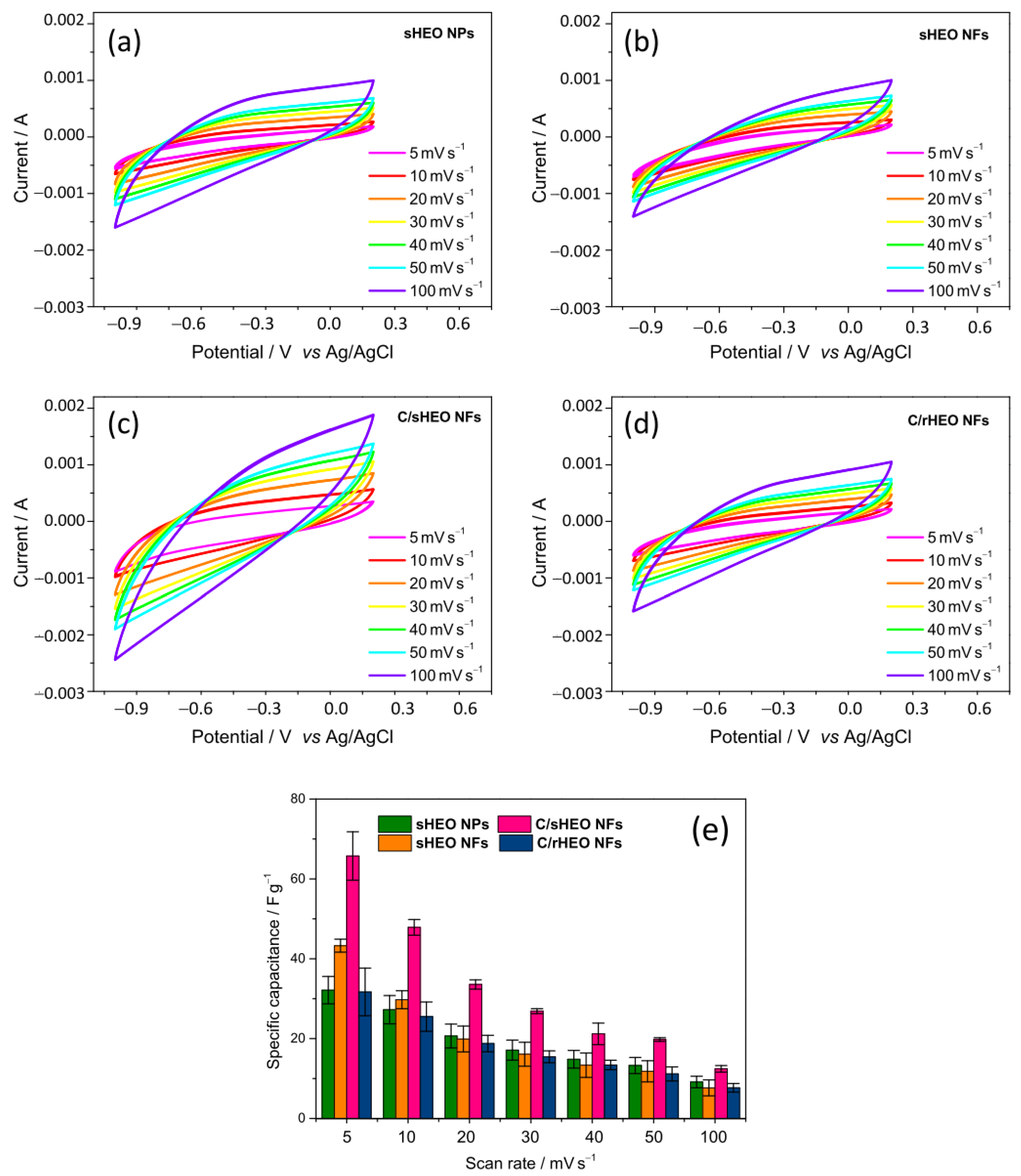
3.3. Electrochemical Analysis

Figure 4 shows the CV performances of the electrodes prepared by using sHEO NPs, sHEO NFs, C/sHEO NFs, and C/rHEO NFs as active materials. The curves are recorded in 0.1 mol L−1 NaCl solution, with sweep rates from 5 to 100 mVs−1 in the potential range from −1 to 0.2 V vs. Ag/AgCl. At lower scan rates, they are featured by a quasi-rectangular shape and exhibit no obvious redox peak. This suggests a purely capacitive behavior due to the perfect EDL formation at the electrode–solution interface. With increasing scan rate, the shape of the CV curves slightly deviates from rectangular and tends to become oval.
The specific capacitances, as calculated according to Equation (1) from the current–voltage curves, are plotted in Figure 4e as functions of scan rate. For each electrode, the value of C diminishes with increasing scan rate, as expected [22,39,51]. By working at low scan speeds, the salt ions have sufficient time to diffuse into the internal pores of the electrodes, which is crucial for the EDL to form. Conversely, when the scan rate increases, salt ions do not have enough time to move and accumulate in the internal pores, and, as a result, the accessible area becomes smaller, and the EDL formation remains incomplete.
In the 5–100 mV s−1 scan rate range, the CDI performance, as monitored by the specific capacitance, improves in the order C/rHEO NFs (8–32 F g−1) ≅ sHEO NPs (9–32 F g−1) < sHEO NFs (8–43 F g−1) < C/sHEO NFs (12–66 F g−1). The improvement is in the same order as the average size of the HEO grains, namely C/rHEO NFs (250 nm) ≅ sHEO NPs (240 nm) < sHEO NFs (200 nm) < C/sHEO NFs (110 nm). Of course, smaller-sized grains result in larger exposed surface area available for the ion adsorption.
The best and the worst capacitive performances pertain to C/sHEO NFs and C/rHEO NFs, respectively. A previous study on common LEO NFs and C/LEO composite NFs [39] has evidenced the relevant role played by morphology of the composite NFs in determining their electrochemical behavior. In C/rHEO NFs, the larger-sized rHEO grains protrude out of the fibrous C matrix (Figure 1d); this is reflected in a detrimental reduction of the contact between the two active material components. On the contrary, in C/sHEO NFs, the smaller-sized sHEO grains are in intimate contact with the host C NFs; this produces a positive effect in terms of overall specific capacitance, which benefits also from the smaller size of the sHEO grains.
Figure S1 compares the specific capacitance of the best performing C/sHEO NFs with that which was previously measured in the C/LEO composite NFs [39]. At 5 mV s−1, in 0.1 M NaCl aqueous solution, C/(Cr0.2Mn0.2Fe0.2Co0.2Ni0.2)3O4 NFs exhibit specific capacitance comparable to that of C/Fe3O4 NFs obtained from a spinnable solution with a higher total metal amount (57.7 vs. 38.5 wt% relative to PAN). This finding indicates that the use of HEOs in place of the common LEOs allows for the reduction of the total metal content in the composites with consequent lowering of the material production costs, which represent the major cost component of the CDI processes [12]. At 100 mV s−1 scan rate, the specific capacitance of C/(Cr0.2Mn0.2Fe0.2Co0.2Ni0.2)3O4 NFs exceeds that of C/MnOx NFs obtained from a spinnable solution with the same total metal amount in the precursor solution, proving that, for fixed metal load, the C/HEO NFs outperform the C/LEO NFs.
Very recently, Lal and Sundara [30] have reported on the electrochemical performance in the electrosorptive water desalination of nano-sized spinel-structured AlCrFeCoNi-HEO NPs and their mixture with biowaste-derived activated carbon functionalized with carboxylic acid (f-CSAC), obtained through a laborious multi-step preparation process involving the carbonization of coconut shells at 800 °C, the subsequent KOH activation at 800 °C, followed by the functionalization in H2SO3:HNO3 3:1 acid mixture. The C values reported in their work refer to a higher NaCl concentration than in the present case (1 M vs. 0.1 M), which would hamper a direct comparison since lower salt concentrations give rise to weaker EDLs which, in turn, results in lower capacitance [51]. Nonetheless, for the sake of completeness, below, those data are compared with the results of the present study. At 100 mV s−1, in 1 M NaCl aqueous solution, the mixture composed of AlCrFeCoNi-HEO NPs and f-CSAC in mass ratio 1:9 exhibits a specific capacitance of 147.5 F g−1, which largely exceeds that of the present C/CrMnFeCoNi-HEO NFs (12.4 F g−1) in aqueous solution, with salt concentration lower by a factor of 10. However, the main contribution to the specific capacitance of AlCrFeCoNi-HEO/f-CSAC mixture is from its f-CSAC component, which, alone, shows a capacitance of 157.5 F g−1 [30]. Conversely, the major contribution to the specific capacitance of C/CrMnFeCoNi-HEO composite NFs seems to be due to the HEO component (Figure 4e). The specific capacitance of AlCrFeCoNi-HEO NPs (12.5 F g−1) also exceeds that measured here in both CrMnFeCoNi-HEO NPs and NFs (9.1 and 7.7 F g−1, respectively). Neglecting the small difference in HEO composition, both the higher molarity of the solution (1 against 0.1 M) and the very small size of AlCrFeCoNi-HEO NPs (<10 nm vs. 240 and 200 nm, respectively) are responsible for this finding.
In 1 mol L−1 NaCl solution, at 5 mV s−1, the C value measured in SnO2/aminated polystyrene co-functionalized graphene oxide nanocomposites (SnO2/PPAS-rGO) prepared under optimized conditions is lower than that obtained in 0.1 mol L−1 NaCl solution, at the same scan rate, in C/CrMnFeCoNi-HEO composite NFs prepared without optimization (~42 against 65.7 F g−1) [51]. Finally, a lower specific capacitance (56 F g−1) pertains also to commercial activated carbon (AC) in 0.5 M NaCl solution, at 2 mV s−1 [52].

4. Conclusions

HEOs and carbon/HEO composites are prepared and physicochemically characterized. In order to explore the possibility of using them as active electrode materials for the CDI of water, their capacitive behavior is evaluated in this preliminary study. To investigate the effect of the material size and morphology, spinel-structured CrMnFeCoNi-HEO NPs and NFs are prepared by the sol–gel method and electrospinning technique, respectively. To study the influence of the HEO lattice structure and of a fibrous host carbon matrix, electrospun composite NFs are further produced with embedded spinel-structured CrMnFeCoNi- and rock-salt-structured MgCoNiCuZn-HEO grains.
In the range scan rates investigated (5–100 mV s−1), the specific capacitance improves in the order C/(Mg0.2Co0.2Ni0.2Cu0.2Zn0.2)O NFs ≅ (Cr0.2Mn0.2Fe0.2Co0.2Ni0.2)3O4 NPs < (Cr0.2Mn0.2Fe0.2Co0.2Ni0.2)3O4 NFs < C/(Cr0.2Mn0.2Fe0.2Co0.2Ni0.2)3O4 NFs. The comparative discussion of the results of the physicochemical and electrochemical analyses indicates that the size of the HEO grains plays a relevant role. The smaller the grains, the larger the surface available for the adsorption and the higher specific capacity. In pure HEOs, the fibrous morphology favors the formation of smaller-sized HEO grains. The lattice structure of the HEO exerts an indirect influence, as it results in HEO grains with different sizes and size ranges. The carbon matrix provides a positive contribution, which can be synergistically enhanced by the incorporation of small-sized HEO grains.
The preliminary results presented in this work suggest that C/HEO composite NFs possess great potential as low cost and eco-sustainable electrode material for CDI and further open the way to explore different HEOs and their carbon composites for a novel design concept of the CDI electrodes.

Supplementary Materials

The following supporting information can be downloaded at: https://www.mdpi.com/article/10.3390/app13020721/s1, Figure S1: Specific capacitance of C/CrMnFeCoNi-HEO NFs compared with that of C/Fe-, C/Zn-, and C/Mn-LEO NFs.

Author Contributions

Conceptualization, S.S.; methodology, C.T., B.P., I.R., A.A., S.G. and Y.B.; validation and formal analysis, C.T., I.R., A.A., S.G. and Y.B.; data curation C.T., I.R., A.A., S.G., Y.B. and S.S.; writing—original draft preparation C.T., M.G.M., S.S. and Y.B.; writing—review and editing, C.T. and S.S. All authors have read and agreed to the published version of the manuscript.

Funding

This research received no external funding.

Institutional Review Board Statement

Not applicable.

Informed Consent Statement

Not applicable.

Data Availability Statement

The data presented in this study are available on request from the corresponding author.

Conflicts of Interest

The authors declare no conflict of interest.

References

  1. Summary Progress Update 2021: SDG 6—Water and Sanitation for All—UN-Water Publications (July 2021). Available online: https://www.unwater.org/publications/summary-progress-update-2021-sdg-6-water-and-sanitation-all (accessed on 29 December 2022).
  2. Agarwal, A. Desalination of Sea Water—A Solution to Water Scarcity. Int. J. Innov. Sci. Res. Technol. (IJISRT) 2022, 7, 457–461. [Google Scholar]
  3. Skuse, C.; Gallego-Schmid, A.; Azapagic, A.; Gorgojo, P. Can emerging membrane-based desalination technologies replace reverse osmosis? Desalination 2021, 500, 114844. [Google Scholar] [CrossRef]
  4. Oren, Y. Capacitive deionization (CDI) for desalination and water treatment—Past, present and future (a review). Desalination 2008, 228, 10–29. [Google Scholar] [CrossRef]
  5. Anderson, M.A.; Cudero, A.L.; Palma, J. Capacitive deionization as an electro-chemical means of saving energy and delivering clean water. Comparison to present desalination practices: Will it compete? Electrochem. Acta 2010, 55, 3845–3856. [Google Scholar] [CrossRef]
  6. Porada, S.; Zhao, R.; van der Wal, A.; Presser, V.; Biesheuvel, P.M. Review on the science and technology of water desalination by capacitive deionization. Prog. Mater. Sci 2013, 58, 1388–1442. [Google Scholar] [CrossRef] [Green Version]
  7. Zhao, Y.; Hu, X.-M.; Jiang, B.-H.; Li, L. Optimization of the operational parameters for desalination with response surface methodology during a capacitive deionization process. Desalination 2014, 336, 64–71. [Google Scholar] [CrossRef]
  8. Jia, B.; Zhang, W. Preparation and application of electrodes in capacitive deionization (CDI): A state-of-art review. Nanoscale Res. Lett. 2016, 11, 64. [Google Scholar] [CrossRef] [Green Version]
  9. Hatzell, K.B.; Iwama, E.; Ferris, A.; Daffos, B.; Urita, K.; Tzedakis, T.; Chauvet, F.; Taberna, P.-L.; Gogotsi, Y.; Simon, P. Capacitive deionization concept based on suspension electrodes without ion exchange membranes. Electrochem. Commun. 2014, 43, 18–21. [Google Scholar] [CrossRef] [Green Version]
  10. Suss, M.E.; Porada, S.; Sun, X.; Biesheuvel, P.M.; Yoon, J.; Presser, V. Water desalination via capacitive deionization: What is it and what can we expect from it? Energy Environ. Sci. 2015, 8, 2296–2319. [Google Scholar] [CrossRef] [Green Version]
  11. Qin, M.; Deshmukh, A.; Epsztein, R.; Patel, S.K.; Owoseni, O.M.; Walker, W.S.; Elimelech, M. Comparison of energy consumption in desalination by capacitive deionization and reverse osmosis. Desalination 2019, 455, 100–114. [Google Scholar] [CrossRef]
  12. Liu, X.; Shanbhag, S.; Bartholomew, T.V.; Whitacre, J.F.; Mauter, M.S. Cost comparison of capacitive deionization and reverse osmosis for brackish water desalination. ACS EST Eng. 2020, 1, 261–273. [Google Scholar] [CrossRef]
  13. Volfkovich, Y.M. Capacitive deionization of water (A review). Russ. J. Electrochem. 2020, 56, 20–55. [Google Scholar] [CrossRef]
  14. Porada, S.; Borchardt, L.; Oschatz, M.; Bryjak, M.; Atchison, J.S.; Keesman, K.J.; Kaskel, S.; Biesheuvel, P.M.; Presser, V. Direct prediction of the desalination performance of porous carbon electrodes for capacitive deionization. Energy Environ. Sci. 2013, 6, 3700–3712. [Google Scholar] [CrossRef] [Green Version]
  15. Han, B.; Cheng, G.; Wang, Y.; Wang, X. Structure and functionality design of novel carbon and faradaic electrode materials for high-performance capacitive deionization. Chem. Eng. J. 2019, 360, 364–384. [Google Scholar] [CrossRef]
  16. Liu, Y.; Nie, C.; Liu, X.; Xu, X.; Sun, Z.; Pan, L. Review on carbon-based composite materials for capacitive deionization. RSC Adv. 2015, 5, 15205–15225. [Google Scholar] [CrossRef]
  17. Sufiani, O.; Tanaka, H.; Teshima, K.; Machunda, R.L.; Jande, Y.A.C. Enhanced electrosorption capacity of activated carbon electrodes for deionized water production through capacitive deionization. Sep. Purif. Technol. 2020, 247, 116998. [Google Scholar] [CrossRef]
  18. Belaustegui, Y.; Rincón, I.; Fernández-Carretero, F.; Azpiroz, P.; García-Luís, A.; Pacheco Tanaka, D.A. Three-dimensional reduced graphene oxide decorated with iron oxide nanoparticles as efficient active material for high performance capacitive deionization electrodes. Chem. Eng. J. Adv. 2021, 6, 100094. [Google Scholar] [CrossRef]
  19. Linneen, N.; Delnick, F.; Islam, S.Z.; Deshmane, V.G.; Bhave, R. Application of the macro homogeneous line model for the characterization of carbon aerogel electrodes in capacitive deionization. Electrochim. Acta 2019, 301, 1–7. [Google Scholar] [CrossRef]
  20. Huynh, L.T.N.; Pham, T.N.; Nguyen, T.H.; Le, V.H.; Nguyen, T.T.; Nguyen, T.D.K.; Tran, T.N.; Ho, P.A.V.; Co, T.T.; Nguyen, T.T.T.; et al. Coconut shell-derived activated carbon and carbon nanotubes composite: A promising candidate for capacitive deionization electrode. Synth. Met. 2020, 265, 11641. [Google Scholar] [CrossRef]
  21. Wang, G.; Dong, Q.; Ling, Z.; Pan, C.; Yu, C.; Qiu, J. Hierarchical activated carbon nanofiber webs with tuned structure fabricated by electrospinning for capacitive deionization. J. Mater. Chem. 2012, 22, 21819–21823. [Google Scholar] [CrossRef]
  22. Belaustegui, Y.; Zorita, S.; Fernández-Carretero, F.; García-Luis, A.; Pantò, F.; Stelitano, S.; Frontera, P.; Antonucci, P.; Santangelo, S. Electro-spun graphene-enriched carbon fibres with high nitrogen-contents for electrochemical water desalination. Desalination 2018, 428, 40–49. [Google Scholar] [CrossRef]
  23. Liu, Y.; Chen, T.; Lu, T.; Sun, Z.; Chua, D.H.C.; Pan, L. Nitrogen-doped electrospun reduced graphene oxide-carbon nanofiber composite for capacitive deionization. RSC Adv. 2015, 5, 34117–34124. [Google Scholar] [CrossRef]
  24. Kazemi, A.S.; Nataj, Z.E.; Abdi, Y.; Abdol, M.A. Tuning wettability and surface order of MWCNTs by functionalization for water desalination. Desalination 2021, 508, 115049. [Google Scholar] [CrossRef]
  25. Santos, C.; Rodríguez, I.V.; Lado, J.J.; Vila, M.; García-Quismondo, E.; Anderson, M.A.; Palma, J.; Vilatela, J.J. Low-energy consumption, free-form capacitive deionization through nanostructured networks. Carbon 2021, 176, 390–399. [Google Scholar] [CrossRef]
  26. Cheng, Y.; Hao, Z.; Hao, C.; Deng, Y.; Li, X.; Li, K.; Zhao, Y. A review of modification of carbon electrode material in capacitive deionization. RSC Adv. 2019, 9, 24401–24419. [Google Scholar] [CrossRef] [PubMed]
  27. Sarkar, A.; Wang, Q.; Schiele, A.; Chellali, M.R.; Bhattacharya, S.S.; Wang, D.; Brezesinski, T.; Hahn, H.; Velasco, L.; Breitung, B. High-Entropy Oxides: Fundamental Aspects and Electrochemical Properties. Adv. Mater. 2019, 31, 1806236. [Google Scholar] [CrossRef] [PubMed]
  28. Musicó, B.L.; Gilbert, D.; Ward, T.Z.; Page, K.; George, E.; Yan, J.; Mandrus, D.; Keppens, V. The emergent field of high entropy oxides: Design, prospects, challenges, and opportunities for tailoring material properties. APL Mater. 2020, 8, 040912. [Google Scholar] [CrossRef] [Green Version]
  29. Triolo, C.; Xu, W.; Petrovičovà, B.; Pinna, N.; Santangelo, S. Evaluation of Entropy-Stabilized (Mg0.2Co0.2Ni0.2Cu0.2Zn0.2)O Oxides Produced via Solvothermal Method or Electrospinning as Anodes in Lithium-Ion Batteries. Adv. Funct. Mater. 2022, 32, 2202892. [Google Scholar] [CrossRef]
  30. Lal, M.S.; Sundara, R. Multifunctional high entropy oxides incorporated functionalized biowaste derived activated carbon for electrochemical energy storage and desalination. Electrochim. Acta 2022, 405, 139828. [Google Scholar] [CrossRef]
  31. Petrovičovà, B.; Xu, W.; Musolino, M.G.; Pantò, F.; Patané, S.; Pinna, N.; Santangelo, S.; Triolo, C. High-Entropy Spinel Oxides Produced via Sol-Gel and Electrospinning and Their Evaluation as Anodes in Li-Ion Batteries. Appl. Sci. 2022, 12, 5965. [Google Scholar] [CrossRef]
  32. Qiu, N.; Chen, H.; Yang, Z.; Sun, S.; Wang, Y.; Cui, Y. A high entropy oxide (Mg0.2Co0.2Ni0.2Cu0.2Zn0.2O) with superior lithium storage performance. J. Alloys Compd. 2019, 777, 767–774. [Google Scholar] [CrossRef]
  33. Wang, S.-Y.; Chen, T.-Y.; Kuo, C.-H.; Lin, C.-C.; Huang, S.-C.; Lin, M.-H.; Wang, C.-C.; Chen, H.-Y. Operando synchrotron transmission X-ray microscopy study on (Mg, Co, Ni, Cu, Zn)O high-entropy oxide anodes for lithium-ion batteries. Mater. Chem. Phys. 2021, 274, 125105. [Google Scholar] [CrossRef]
  34. Guo, H.-X.; Wang, W.-M.; He, C.-Y.; Liu, B.-H.; Yu, D.-M.; Liu, G.; Gao, X.-H. Entropy-assisted high-entropy oxide with a spinel structure toward high-temperature infrared radiation materials. ACS Appl. Mater. Interfaces 2022, 14, 1950–1960. [Google Scholar] [CrossRef] [PubMed]
  35. Zhang, J.; Yan, J.; Calder, S.; Zheng, Q.; McGuire, M.A.; Abernathy, D.L.; Ren, Y.; Lapidus, S.H.; Page, K.; Zheng, H.; et al. Long-range antiferromagnetic order in a rocksalt high entropy oxide. Chem. Mater. 2019, 31, 3705–3711. [Google Scholar] [CrossRef] [Green Version]
  36. Pantò, F.; Fan, Y.; Frontera, P.; Stelitano, S.; Fazio, E.; Patanè, S.; Marelli, M.; Antonucci, P.; Neri, F.; Pinna, N.; et al. Are electrospun carbon/metal oxide composite fibers relevant electrode materials for Li-Ion batteries? J. Electrochem. Soc. 2016, 163, A2930. [Google Scholar] [CrossRef]
  37. Senthamizhan, A.; Balusamy, B.; Aytac, Z.; Uyar, T. Grain boundary engineering in electrospun ZnO nanostructures as promising photocatalysts. CrystEngComm 2016, 18, 6341–6351. [Google Scholar] [CrossRef] [Green Version]
  38. Li, Y.; Zhang, H.; Zhang, X.; Wei, L.; Zhang, Y.; Hai, G.; Sun, Y. Enhanced acetone sensing performance based on hollow coral-like SnO2–ZnO composite nanofibers. J. Mater. Sci. Mater. Electron. 2019, 30, 15734–15743. [Google Scholar] [CrossRef]
  39. Santangelo, S.; Pantò, F.; Triolo, C.; Stelitano, S.; Frontera, P.; Fernández-Carretero, F.; Rincon, I.; Azpiroz, P.; García-Luís, A.; Belaustegui, Y. Evaluation of the electrochemical performance of electrospun transition metal oxide-based electrode nanomaterials for water CDI applications. Electrochim. Acta 2019, 309, 125–139. [Google Scholar] [CrossRef]
  40. Pantò, F.; Fan, Y.; Stelitano, S.; Fazio, E.; Patanè, S.; Frontera, P.; Antonucci, P.; Pinna, N.; Santangelo, S. Are Electrospun Fibrous Membranes Relevant Electrode Materials for Li-Ion Batteries? The Case of the C/Ge/GeO2 Composite Fibers. Adv. Funct. Mater. 2018, 28, 1800938. [Google Scholar] [CrossRef]
  41. Sun, Z.; Zhao, Y.; Sun, C.; Ni, Q.; Wang, C.; Jin, H. High entropy spinel-structure oxide for electrochemical application. Chem. Eng. J. 2022, 431, 133448. [Google Scholar] [CrossRef]
  42. Stygar, M.; Dabrowa, J.; Mozdzierz, M.; Zajusz, M.; Skubida, W.; Mroczka, K.; Berent, K.; Swierczek, K.; Danielewski, M. Formation and properties of high entropy oxides in Co-Cr-Fe-Mg-Mn-Ni-O system: Novel (Cr, Fe, Mg, Mn, Ni)3O4 and (Co, Cr, Fe, Mg, Mn)3O4 high entropy spinels. J. Eur. Ceram. Soc. 2020, 40, 1644–1650. [Google Scholar] [CrossRef]
  43. Mao, A.; Xiang, H.Z.; Zhang, Z.G.; Kuramoto, K.; Zhang, H.; Jia, Y. A new class of spinel high-entropy oxides with controllable magnetic properties. J. Magn. Magn. Mater. 2020, 497, 165884. [Google Scholar] [CrossRef]
  44. Chen, Y.; Fu, H.; Huang, Y.; Huang, L.; Zheng, X.; Dai, Y.; Huang, Y.; Luo, W. Opportunities for High-Entropy Materials in Rechargeable Batteries. ACS Mater. Lett. 2020, 3, 160–170. [Google Scholar] [CrossRef]
  45. Kheradmandfard, M.; Minouei, H.; Tsvetkov, N.; Vayghan, A.K.; Kashani-Bozorg, S.F.; Kim, G.; Hong, S.I.; Kim, D.-E. Ultrafast green microwave-assisted synthesis of high-entropy oxide nanoparticles for Li-ion battery applications. Mater. Chem. Phys. 2021, 262, 124265. [Google Scholar] [CrossRef]
  46. Zhu, P.; Hong, Y.; Liu, B.; Zou, G. Titanium Carbide–Carbon Composite Nanofibers Prepared by Electrospinning Polyacrylonitrile. Chem. Lett. 2009, 38, 784–785. [Google Scholar] [CrossRef]
  47. Tao, B.; Yang, W.; Zhou, M.; Qiu, L.; Lu, S.; Wang, X.; Zhao, Q.; Xie, Q.; Ruan, Y. Designing a carbon nanofiber-encapsulated iron carbide anode and nickel-cobalt sulfide-decorated carbon nanofiber cathode for high-performance supercapacitors. J. Colloid Interface Sci. 2022, 621, 139–148. [Google Scholar] [CrossRef]
  48. An, H.R.; Bae, S.A.; Kim, C.Y.; Son, B.; Park, J.I.; Kim, H.; Lee, M.; Yang, K.E.; Lee, S.M.; Kim, S.H.; et al. Highly efficient and stable catalytic reactivities of iron (-oxide) incorporated carbide nanofiber composite for environmental and bio-medical application. J. Mater. Res. Technol. 2021, 15, 5232–5243. [Google Scholar] [CrossRef]
  49. Usharani, N.J.; Bhandarkar, A.; Subramanian, S.; Bhattacharya, S.S. Antiferromagnetism in a nanocrystalline high entropy oxide (Co, Cu, Mg, Ni, Zn)O: Magnetic constituents and surface anisotropy leading to lattice distortion. Acta Mater. 2020, 200, 526–536. [Google Scholar] [CrossRef]
  50. Usharani, N.J.; Shringi, R.; Sanghavi, H.; Subramanian, S.; Bhattacharya, S.S. Role of size, alio-/multi-valency and non-stoichiometry in the synthesis of phase-pure high entropy oxide (Co, Cu, Mg, Na, Ni, Zn)O. Dalton Trans. 2020, 49, 7123–7132. [Google Scholar] [CrossRef]
  51. Xie, K.; Yu, J.; Zhang, X.; Hu, S.; Liu, R.; Song, H.; Shen, J.; Wang, Y.; Li, A.; Zhang, S. Capacitive desalination of a low concentration aqueous sodium chloride solution based on a SnO2 and polystyrene co-functionalized graphene oxide electrodes. Chem. Eng. J. 2021, 414, 128747. [Google Scholar] [CrossRef]
  52. Folaranmi, G.; Bechelany, M.; Sistat, P.; Cretin, M.; Zaviska, F. Comparative investigation of activated carbon electrode and a novel activated carbon/graphene oxide composite electrode for an enhanced capacitive deionization. Materials 2020, 13, 5185. [Google Scholar] [CrossRef] [PubMed]
Figure 1. Main results of the morphological and compositional analyses. (ad) Representative SEM images of (a) sHEO NPs, (b) sHEO NFs, (c) C/sHEO composite NFs, and (d) C/rHEO composite NFs. (e) Diameter distribution of electrospun NFs. (fi) Elemental composition of (f) sHEO NPs, (g) sHEO NFs, (h) C/sHEO NFs, and (i) C/rHEO NFs. (j,k) TEM images of (j) sHEO NPs and (k) sHEO NFs. (l) Size and size range of HEO NPs in the samples. The left arrow is located in correspondance of the grey bar and indicates that the y-axis for bars is on the left (particle size range); the right arrow is located in correspondance of the blue symbol and indicates that the y-axis for coloured symbols is on the right (average particles size).
Applsci 13 00721 g001
Figure 2. XRD patterns of (a) sHEO NPs, sHEO NFs, and C/sHEO composite NFs and (b) C/rHEO composite NFs (the pattern of rHEO NFs is also reported for comparison purposes).
Applsci 13 00721 g002
Figure 3. Micro-Raman spectra of the samples.
Applsci 13 00721 g003
Figure 4. (ac) CV curves of (a) sHEO NPs, (b) sHEO NFs, (c) C/sHEO composite NFs, and (d) C/rHEO composite NFs and (e) corresponding specific capacitance as a function of potential scan rate.
Applsci 13 00721 g004
Disclaimer/Publisher’s Note: The statements, opinions and data contained in all publications are solely those of the individual author(s) and contributor(s) and not of MDPI and/or the editor(s). MDPI and/or the editor(s) disclaim responsibility for any injury to people or property resulting from any ideas, methods, instructions or products referred to in the content.

