
Design Criteria for High-Gradient Radio-Frequency Linacs

SLAC National Accelerator Laboratory, 2575 Sand Hill Road, Menlo Park, CA 94025, USA
Appl. Sci. 2023, 13(19), 10849; https://doi.org/10.3390/app131910849
Submission received: 30 May 2023
/
Revised: 9 September 2023
/
Accepted: 26 September 2023
/
Published: 29 September 2023
(This article belongs to the Special Issue RF-Based Undulators and High-Gradient Accelerator Fed by High-Frequency Electromagnetic Devices)
Abstract
:This article will review methods used at the SLAC National Accelerator Laboratory and other world accelerator laboratories to design high-gradient normal conducting accelerating structures. A quest for compact radio-frequency linacs fueled decades of studies toward a higher accelerating gradient. A major phenomena limiting the increase of the gradient is vacuum radio-frequency breakdown; therefore, this paper will address the breakdown physics and discuss approaches that reduce the breakdown probability. This discussion will cover both the electrical design and fabrication technology of the accelerating structures to achieve practical operating accelerating gradients in excess of 100 MV/m. Most of the data described here were obtained during the development of 11 GHz linacs for electron–positron linear colliders, so extrapolation of the results to other frequencies should be performed cautiously.
1. Introduction
The accelerating gradient is one of the crucial parameters affecting the design, construction, and cost of the next-generation linear accelerators. The challenge is to develop reliable and cost-effective high-gradient linacs or, in the case of radio-frequency (rf) beam diagnostic devices, to increase the measurement resolution.
The typical working frequencies of normal conducting linear accelerators are from about 1 GHz to 12 GHz. The accelerating gradient of the long-lived SLAC S-band linac is about 17 MV/m [1]. During the development of the Next Linear Collider (NLC)/Japan Linear Collider (JLC), an X-band test accelerator operated at a 65 MV/m unloaded gradient [2,3]. The CERN-based linear collider design CLIC requires a 100 MV/m loaded gradient at 12 GHz in accelerating structures with heavy wakefield damping [4]. Future accelerators, like compact synchrotron light sources or inverse Compton scattering gamma ray sources [5,6], may need even higher gradients. High field gradients are required in rf devices for beam manipulation and beam diagnostics where short rf wavelengths are beneficial for microwave undulaltors [7,8] and rf deflectors [9,10,11,12].
The history of this topic goes back many decades. However, much of the investment in its systematic research began with the development of normal conducting linear colliders, for which operating gradients had to be close to 100 MV/m to be feasible. This article summarizes the major results of this work.
One of the main goals of this article is to provide practical recipes for the development of state-of-the-art normal conducting high-gradient rf linacs. To achieve this goal, I first review previous research and then discuss the physics of the main obstacles to high-gradient operation: rf breakdown, pulsed surface heating, and field emission. I base this physics discussion on my 2018 review paper [13], to which I have added the results of experiments carried out since, for example, high-gradient tests of C-band cavities [14] and multicell cryogenic accelerating structures [15]. I continue with a description of practical design approaches and end with a brief summary.
2. Overview of High-Gradient Studies for Particle Accelerators
Experimental work on high-gradient acceleration was a major part of early electron–positron linear collider development; see, for instance, the work of V. E. Balakin et al. [16] and of G. Loew et al. [17]. The work of G. Loew et al. [17] considered that the rf breakdowns were directly linked to the peak rf electric field, while neither the peak magnetic field nor rf power were considered relevant. Therefore, they were studying the peak limit value of the electric field that generates breakdowns as a proxy for the accelerating gradient. This work was carried out at different frequencies: S-band, C-band, and X-band. They found that the maximum peak surface electric field achievable without rf breakdowns grows with the square root of the frequency. This analysis leads to the idea that the maximum accelerating gradient, limited by breakdown, increases with frequency. Later, other research carried out at CERN [18,19,20] in the frequency range from 21 to 39 GHz concluded that there is no increase in the maximum achievable gradient at higher frequencies. Both studies considered rf breakdown as a phenomenon generated when the peak electric field exceeds a certain threshold. Recent tests of single accelerating cavities at the S-band and C-band [14] do not show obvious frequency dependence of the achievable gradients.
Major work to understand and mitigate the effects of rf breakdown were conducted during the development of the normal conducting 11.424 GHz linear collider NLC/GLC [2,3,21], which has been followed by the 12 GHz CERN-based linear collider CLIC [22]. NLC/JLC work looked at both traveling wave (TW) and standing wave (SW) accelerating structures, while CLIC considered only TW structures. During the NLC/JLC work, the statistical nature of rf breakdown became apparent [2,3,21,23], which fundamentally changed our approach to studying rf breakdown phenomena and allowed us to quantify it: for most accelerating structures exposed to the same rf power and pulse shape, the number of rf breakdowns per pulse is nearly steady or slowly decreasing over – pulses. The breakdown probability became one of the main quantitative requirements characterizing the high-gradient performance of rf linacs. For example, the CLIC linear collider requires the rf breakdown probability to be less than per pulse per meter for a loaded accelerating gradient of 100 MV/m in order to maintain the electron–positron collision’s luminosity.
As technology progressed, sophisticated manufacturing and surface preparation techniques and systematic rf processing methods were developed [24,25,26,27]. As a result of this R&D, practical 11.4 GHz TW accelerating structures, which are CLIC prototypes, run at breakdown rates of about per pulse per meter at unloaded gradients up to 120 MV/m and a ∼200 ns pulse length [28]. TW structures that include wakefield damping work at about 100 MV/m for similar breakdown rates [28,29]. Continuing studies of new geometries, materials, and manufacturing methods at 11.424 GHz show the potential to reach 150 MV/m accelerating gradients with similarly low breakdown rates [15,30,31,32,33].
Advances in understanding limitations on accelerating gradients go beyond linear colliders. Accelerators are used in applications such as inverse Compton scattering gamma ray sources [5,6], compact free-electron lasers (FELs) [34,35,36], and compact medical linacs for hadron therapy [37,38,39,40,41,42].
Modern high-gradient devices, such as photo-rf guns [43,44,45], fourth harmonic linearizers for FELs [46], rf deflectors [9,10,47,48,49], and rf undulators [7,8], all use these technologies and methods, developed and sustained by studies of high-gradient accelerators.
Due to large investment into the development of X-band (11–12 GHz) linear colliders, the X-band accelerating cavities are the most investigated in terms of their high-gradient performance [23,31,50,51,52]. I found that the breakdown probabilities depend on numerous factors, including pulsed surface heating [53,54], the peak electric field, the peak magnetic field [55], and the peak Poynting vector [56]. Regarding cavity materials, in my experiments at both the X-band and C-band I found that CuAg cavities have a lower breakdown probability than copper cavities [14,18,23].
Continuing my study of the cavity materials, I found that normal conducting cryogenic accelerating cavities showed that these structures perform better at high gradients than room temperature cavities [57,58,59,60]. For example, in tests of cryogenic copper single-cell SW cavities I achieved world-record accelerating gradients of 250 MV/m.
3. RF Breakdown
3.1. RF Breakdown Properties
A vacuum rf breakdown is an event that causes a measurable change in the RF power transmitted through and reflected from a resonator within nanoseconds. This breakdown triggers an increase in gas pressure, a bright flash of visible light, and a burst of X-rays.
The properties of rf breakdowns vary between broadband structures, such as TW accelerating structures and high-power waveguides and narrow-band SW accelerating structures. In broadband structures, the power transmitted through the structure drops to almost immeasurable levels within 20–200 ns during a breakdown. Up to 80% of the incoming RF power can be lost in this process.
Conversely, in SW structures most of the incoming RF power is reflected from the cavity [51]. However, it is worth noting that some multicell SW structures do not produce significant reflection during breakdowns.
3.2. Breakdown Rate
In the course of studies of high-gradient acceleration for NLC/JLC linear colliders, I found that if rf pulses of the same shape and amplitude are applied to the accelerating structure, then the probability of rf breakdown (or the number of breakdowns per number of rf pulses) is practically constant or changes slow. This result is more or less independent of the conditioning algorithm and the type of structure (SW or TW).
I show a typical example for the quantity of accumulated breakdowns vs. pulse number for a short SW cavity [31] in Figure 1a. The number of accumulated breakdowns follows a linear fit, the slope of which is proportional to the breakdown rate. This is how almost every accelerating structure I have tested behaves.
Further, I show the histogram of the number of pulses between subsequent breakdowns in Figure 1b. The histogram shows an exponential distribution, which means that events happen continuously and independently. Meanwhile, unlike in SW cavities, in TW structures the rf breakdown statistics are better described by a double-Poisson distribution [67,68], where a short-time-scale distribution is associated with post-breakdown damage and the longer-time-scale distribution with the breakdown trigger. Since the physics of the interaction between the breakdown currents and electromagnetic fields stored in SW structures limits the degree of post-breakdown damage, the longer-time-scale Poisson distribution dominates the breakdown probability for the SW structures.
Since the importance of the breakdown rate was understood two decades ago, it became common to present test results of high-power accelerating structures as the breakdown rate map or dependence of the breakdown probability rate on rf pulse length or, more generally, on rf pulse shape [31,69]. The use of these breakdown rate maps to characterize the high-gradient performance of the structures lets us avoid such non-precise terms as “gradient limit” or “breakdown limit”.
3.3. Initial Processing
After installing a new accelerating cavity in the test setup, it undergoes the so-called initial processing. Processing starts with a low rf power that is gradually increased, while the vacuum level and rf breakdown rate are observed and maintained at empirically determined levels. The duration of the processing, after which the breakdown rate is in a steady state, varies greatly depending on the specifics of the structure manufacturing and preparation process and the processing algorithm. This may take from a few hours and thousands of breakdowns to weeks or months and millions of breakdowns. For some structures, the breakdown rate never stabilizes during the period allocated for the test. Typically, longer structures take longer to process. Depending on the initial conditions, the breakdown rate either decreases or increases with time. The breakdown rate maps discussed below were taken after initial conditioning when the breakdown rate is at a steady state over millions of rf pulses.
The physics of this processing is not clear. For example, the traditional explanation that the initial processing clears the dust particles or eliminates pre-existing field emitters cannot account for structures that exhibited anomalous processing with lower breakdown rates at the beginning of the test, which I observed in tests of the CuAg cavities.
Recent analyses of the conditioning process of CLIC TW prototypes suggests that the phenomena are a result of the exposure of the metal surface to the pulsed rf fields, not due to accumulated breakdown events [70]. However my experiments with single-cell SW structures do not support this hypotheses, so this phenomenon may be a property of TW structures or cavity-surface processing specific for TW structures. Another possible explanation for the difference is a crosstalk between neighboring cells, the physics of which is also not understood.
3.4. Reproducibility of High-Power Test Results
One of the most important results of high-power testing of multiple X-band TW and SW cavities is the reproducibility of breakdown rate maps. I found that the breakdown rate maps are remarkably reproducible for cavities of the same shape made from the same materials. This observation has been confirmed for cavities made by various manufacturers and for a range of initial metal surface conditions. As an example, I show in Figure 2 the breakdown rate maps for three cavities of the same shape, two made in KEK, Japan, and one made at the INFN-LNF, Italy. Note that these are stationary breakdown rate maps obtained after initial conditioning.
This reproducibility has several important practical implications. Firstly, the breakdown performance could be predicted for cavities of new geometries. Understanding this led to the development of empirical quantities that have become a practical tool for designing accelerating structures [31,56,72,73]. However, extrapolation of data outside of a well-studied parameter space should be performed with caution.
Secondly, a physical model capable of predicting the rf breakdown characteristics of accelerating cavities should have the shape of the structure and the material as its main parameters. At the time of publication, such a model is still far away.
3.5. Geometric Dependence
Here, I discuss the results of the cavity geometry studies conducted using short SW accelerating structures. I started with experiments with cavities of a disk-loaded-waveguide type, which are typical for linear accelerators (an example of such an X-band structure with a beam iris radius of 3.75 mm is shown in Figure 3a). I have built and tested cavities with several different beam aperture sizes. The results of these tests are summarized in [31] and shown in Figure 4a,b. The breakdown probability for structures with different iris sizes was correlated with peak rf magnetic fields and varied with the rf pulse length as if dependent on peak pulse surface heating (see Figure 4b)) rather than the peak surface electric field or accelerating gradient (see Figure 4a)).The magnitude of peak pulse heating is approximately proportional to the square root of the rf pulse length. These findings prompted a dedicated study of rf pulse heating [54] and experiments with hard materials [74]. Note that originally high rf magnetic fields and moderate electric fields were found to be the sources of rf breakdowns in the couplers of NLC structures [53].
Meanwhile, Grudiev et al. made a successful attempt to find a local field quantity that can describe the breakdown behavior observed in many experiments [56]. They found that the peak of a modified Poynting vector correlated to the measured (or scaled) breakdown rate in seventeen TW and four SW cavities, including the cavities that are described above. To understand how the Poynting vector is correlated with the breakdown rate in my experiments, I scaled the peak pulse surface heating with the ratio . The results of this scaling are shown in Figure 4c. Because of the similar geometry of the cavites, this ratio is similar in all three structures. Again, because of this similarity, the breakdown rate in these particular structures is correlated with both the peak pulsed heating and the peak Poynting vector.
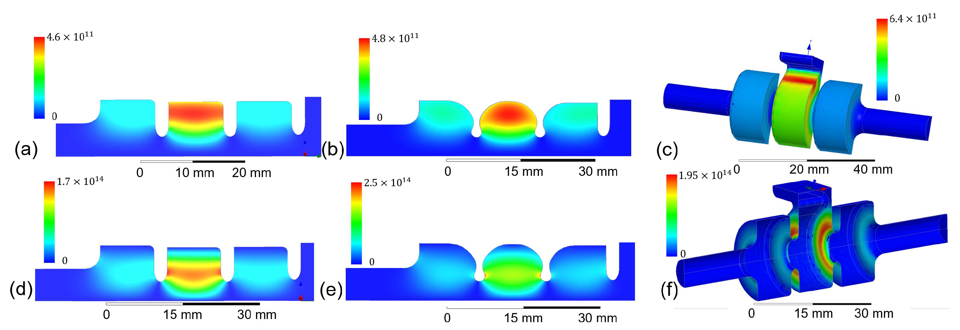
To unwrap this correlation, SW cavities were tested that have the peak value of the Poynting vector increased and decreased, with respect to a “standard” cavity, as shown in Figure 3a. The structure with a nose-cone cell shape shown in Figure 3b has been designed with minimized peak surface magnetic fields [75]. However the ratio is almost doubled from 390 Ohm to 632 Ohm. Both of these cavities are fed with rf power on-axis. A third structure shown in Figure 3c is fed off-axis [76]. Peak pulse surface heating is increased on the coupling irises, thus decreasing to 301 Ohm. The results of high-power tests for these three cavities are shown in Figure 5. The breakdown rate is more dependent on the Poynting vector than on the accelerating gradient or peak pulse surface heating. Plus, the location of the RF breakdown damage observed during the autopsy of the side-coupled cavity correlates with the region of the highest values of the surface Poynting vector.
Because the correlation between the magnitude of the peak Poynting vector and the rf breakdown rate has been derived from numerous experiments, it has remarkable predictive power. However, there are many exceptions that confirm that its physics has not been understood. The SW cavities with a narrow-gap choke [77], three-cell side-coupled structure [76], photonic band gap that has an enhanced magnetic field [78], X-band deflector [49], and S-band high-gradient proton TW accelerator [38] all had higher breakdown rates than would be predicted using the Poynting vector, and the breakdown damage was not located in the region of the maximum of the Poynting vector.
Figure 3.
X-band structures with different ratios of peak Poynting vector to peak [79]. All the structures have the same a = 3.75 mm aperture radius. The distribution of and magnitude of Poynting vector are shown above and below, respectively: (a,d) for on-axis coupled structure with elliptical iris, max. kA/mm, =173 W/m, ratio is 390 Ohm; (b,e) for on-axis coupled structure with optimized shape, max. kA/mm, W/m, ratio is 632 Ohm; (c,f) for side-coupled structure with elliptical iris, max. kA/mm, W/m, ratio is 301 Ohm. The fields are normalized to rf power losses of 10 MW in the cavity.

Figure 4.
Breakdown probability plots for three SW cavities with different aperture radii “a” [31,79]: , , and . Cavities with and are powered by a shaped rf pulse with charging time of ∼170 ns and flat top of 200 ns, and for structure with the flat top is 150 ns. Breakdown rate is vs. (a) accelerating gradient; (b) pulse heating; (c) pulse heating multiplied by .

Figure 5.
Breakdown probability plots for three SW cavities with different [79]. The cavities are fed with a shaped rf pulse with 200 ns flat top and ∼170 ns charging time. Breakdown rate is vs. (a) accelerating gradient; (b) pulse heating; (c) pulse heating multiplied by . Aperture radius is 3.75 mm and for all three structures.

3.6. Material Studies
One of the main results of the study of reproducibility and cavity geometry was the understanding that, for the same cavity shape, the high-gradient performance is determined by the properties of the bulk material. Therefore, studies of hard copper alloys, bimetallic cells, and cryogenic cavities followed. Note that usually the initial state of the surface has little effect on the final high-gradient performance, which, for example, contradicts our knowledge of the high-gradient operation of superconducting cavities, which typically operate at much lower surface fields.
3.6.1. Hard Metals
After I realized that there is a correlation between the peak pulse surface heating and the breakdown rate [31], a twofold program was initiated, one dedicated to the study of pulse heating damage [54] and the other one to study the breakdown performance of hard, non-heat-treated copper alloys [74], including CuZr, CuCr, CuAg, and copper of high 6N and 7N purity. To do this, we built a vacuum vessel in which we could high-power test cavities constructed of bolted-together cells. One such structure is shown during its assembly in Figure 6. Of all these experiments, cavities built from hard copper and hard copper–silver showed the largest improvement, and cavities made out of hard CuAg have the best performance outmatched only by cryogenic cooper.
I show the results of the high-power test of a hard copper cavity in Figure 7a. A hard copper cavity with a beam aperture radius of 2.75 mm had an order of magnitude lower rf breakdown rate at a gradient of 175 MV/m than a cavity of the same shape joined by means of high-temperature brazing.
I used the same bolted-together setup to conduct experiments with cavities made of hard CuAg alloys. Compared to both soft copper cavities and even hard copper cavities, the CuAg structures demonstrated lower rf breakdown rates and faster processing. As shown in Figure 7b, a hard CuAg cavity had a breakdown rate below per pulse per meter at a gradient of 200 MV/m [80]. I note that there is overwhelming experimental evidence that a particular cell clamping method has a decisive effect on high-power test results. It is often overlooked that metal-to-metal contact alone produces poor results [81].
One method to build an accelerating cavity without exposing it to high temperatures is electroforming, where metal is deposited on a precision-machined aluminum mandrel using an electrochemical process. Then the mandrel is removed by chemical etching. Experimental data obtained from high-power testing of electroplated and electroformed cavities were published in [82,83]. In a recent experiment, a nickel cavity was electroformed, while the surface exposed to rf fields was plated with a thin layer of gold. The measured rf breakdown rates for these cavities were the same or higher than those for soft copper cavities. Although electroformed cavities have not outperformed soft copper ones, this fabrication method has great potential for the economic mass production of precision components of the accelerating structures.
3.6.2. Clad Structures
Based on experience with DC vacuum breakdown, where molybdenum and stainless steel have better breakdown characteristics than copper, several cavities were fabricated where iris tips, the location of the highest surface electric fields and rf power flow, were made of these materials (Figure 8). These so-called clad cavities were manufactured by various institutions and then tested at a high power. The anticipated difficulty in manufacturing such clad structures is associated with damage to the bimetallic joint during high-temperature bonding or brazing.To solve this problem and eliminate the need for high-temperature brazing, cells with molybdenum iris tips made at KEK [79] were clamped together. I reported high-power test results in [90]; the structures did not surpass standard cavities, probably due to damage to the bimetallic joint by pulsed heating.
The clad structures that were brazed were developed separately by the Haimson Research Corporation (HRC). Unlike KEK, which built short SW cavities, HRC developed full-scale TW accelerating structures assembled from clad cells with stainless steel and molybdenum iris tips. HRS has gone to great lengths to minimize damage to the tip–cell junction. High-power tests of copper and stainless steel clad TW structures were conducted at MIT. The stainless steel structure showed a better breakdown performance than the copper structure during initial conditioning [91]. Note that the breakdown rate map was not obtained during this experiment. Another HRS project, a TW structure with molybdenum iris tips, has been completed [92], but its high-power test has not been finished.
To summarize, the clad structure approach has not produced major improvements in high-gradient performance; the effort that went into this complex technological problem was relatively small, but it should not be ignored, especially for high-power TW structures and klystrons.
3.6.3. Normal Conducting Structure at Cryogenic Temperatures
The study of materials now extends down to cryogenic temperatures. Here, I will focus on normally conducting cryogenic cavities. The physics of gradient limitation in superconducting cavities has more to do with Q-value degradation due to field emission currents and the quenching of superconductivity due to strong rf magnetic fields than with rf breakdown. Gradients in superconducting cavities are usually much lower than those achieved with normal conducting cavities [93,94].
My cryogenic experiments were inspired by hypotheses that explain the properties of the rf breakdown rates involving defects in metallic crystal lattices moving under forces induced by rf electric and magnetic fields. This movement of crystal dislocations decreases with the decreasing temperature of the cavity. To study this phenomenon, we invented and fabricated an experimental setup for testing cryogenically cooled short SW cavities at high rf power [95]. My first cryo experiment was not successful: the breakdown probability was higher than that in room temperature cavities. In this experiment, the rf vacuum and cryo-vacuum were connected, so the gasses from the cryosat contaminated the surfaces exposed to high rf fields. We have modified the cryostat in order to separate the cryo vacuum and the cavity vacuum [96]. The second cavity, cooled to 45 K, showed a much lower breakdown rate than room-temperature cavities [58,97,98] (Figure 9). The cavity operated at a low breakdown rate with a record accelerating gradient of 250 MV/m.
4. Field Emission Currents
Metal surfaces exposed to high electric fields emit electrons, so-called field emission currents. The field emission currents interacting with rf fields of accelerating structures are commonly referred to as dark currents. Dark currents are typically observed in operating high-gradient accelerating cavities, but, unlike rf breakdowns, they are relatively easy to measure since they are present during every rf pulse and change little from pulse to pulse. Also, dark currents are not as disruptive to the accelerating structure operation as rf breakdowns but produce unwanted beam loading and ionizing radiation, which could blind beam diagnostics.
A theory of field emission was developed for DCs and is well understood for microscopically simple emitters [102]. Field emission is believed to be a trigger for DC breakdowns, so a significant effort was directed toward understanding the dark current as a possible precursor to vacuum rf breakdown in accelerating structures [67,103,104]. However, even though dark currents in accelerating structures are easily measured, a quantitative understanding of the dark current parameters and their possible connection to the breakdown trigger remain elusive.
I note an empirical observation, which is remarkably reproducible for numerous high-gradient cavities. The dark current magnitude is a violent function of applied rf fields and is typically graphed on a semi-log so-called Fowler–Nordheim plot using vs. , where is the magnitude of the current and E is peak surface electric field. The slope of the dark current on a Fowler–Nordheim plot represents the field-enhancement factor . The physics of in practical cavities is not understood, despite a significant number of hypotheses. During the high-gradient operation of structures, we typically observe that peak macroscopic surface electric fields multiplied by the are equal to about 1 volt per angstrom, or 10 GV/m. We note that this is true for conditioned cavities, where the breakdown rate is relatively constant. This empirical observation is of little practical value because it cannot be used to predict rf breakdown rates, unlike peak pulse surface heating or a modified Poynting vector.
5. Design Considerations for High-Gradient Accelerating Structures
The dependence of the breakdown rate on macroscopic geometry and circuit parameters and its independence on details of metal surface preparation (to a degree) of the normal conducting cavities is a major result of the systematic studies of the rf breakdown physics. This understanding coupled with the reproducibility of the results for cavities of the same shape allows us to formulate empirical design criteria for the high-gradient structures. Illustrations of the application of these criteria can be found in [67,105,106,107]. I note that these were developed for X-band accelerating structures and their use at other frequencies has to be conducted cautiously.
5.1. Surface Electric Fields
As I discussed above, peak surface electric fields were initially believed to be the main cause of rf breakdown [16,103]. This view changed as the correlation of the rf breakdown trigger with peak pulse surface heating and power flow was understood; see, for example, [52,108]. As experimental data accumulated, it was understood that for low breakdown rate operation, < per pulse per meter, the peak surface electric field should be below 250 MV/m [109]. I do not have much evidence that this 250 MV/m value depends on frequency; however, I have a few exceptions where the peak field was higher, but these were not typical and are still being worked on to confirm it [14,58]. Note that this criterion has no pulse length dependence.
5.2. Kilpatrick’s Criterion
One of the most useful attempts to understand the law governing sparks in a vacuum was made by W. D. Kilpatrick [110] in the 1950s. Kilpatrick analyzed rf and DC breakdown data and found the conditions that lead to breakdown-free operation. Later, T. J. Boyd [111] conveniently expressed the Kilpatrick results in the formula f = 1.64 ··, where f is the rf frequency in megahertz and E is the surface electric field in megavolts per meter. This is known as the Kilpatrick’s criterion. This criterion has often been and is still used as a basis for evaluating the peak surface electric field limit, especially at frequencies below GHz where systematic data on breakdown characteristics are scarce. However, at higher frequencies this criterion is rarely used for modern designs as it is being replaced by the more precise and practical parameters described in this article.
5.3. Surface Magnetic Fields and Pulsed Surface Heating
When a metal surface is exposed to a pulse of high rf magnetic fields, a small surface layer heats up and expands, thus creating mechanical stress near the surface [112]. When this stress reaches a value comparable with the yield stress of the metal, microscopic damage can be observed, which usually starts at grain boundaries [54]. Copper reaches this stress at about 50 °C of peak pulse surface heating. A simple formula, which was derived using linear heat propagation models, calculates the peak pulse surface heating for copper [53,112]:
where is the surface rf magnetic fields, is the rf frequency, and is the pulse length. I note a pulse-length dependence of the peak temperature. The typical pulse length of the X-band accelerating structures is 100…1000 ns.
When designing accelerating structures, we want the rf magnetic fields to be low enough that the peak surface heating during the rf pulse stays below 50 °C to avoid any damage to the copper surface.
5.4. RF Power Flow
The dependence of the rf breakdown rate on the rf power flow became a topic of systematic research during NLC/JLC development, when 1.8 m long X-band TW accelerating structures could not be processed to the required gradient of 65 MV/m. This gradient was much lower than the one reached previously with short SW cavities [113]. The main hypothesis at the time was that the group velocity somehow determined the limiting gradient: the lower the group velocity, the higher the gradient. The physics of this empirical dependence was not understood.
Then, an ablation limit [52] was introduced as . I noticed that numerous TW structures showed excessive damage at the ablation limit above 100 MW .
This was followed by Walter Wuensch’s ratio of rf power, which flows through the cell to the aperture circumference C, [72] and then Alexej Grudiev’s peak modified Poynting vector [56].
Currently, both and are used for rf design where should be less than MW/mm for ns and less than 3 MW/mm for the same pulse length in order to achieve an rf breakdown rate below per pulse per meter [109].
5.5. Stored Energy
The relation between electromagnetic energy stored in an accelerating structure and its rf breakdown rate is not understood; however, a linac designer should make an effort to make it as low as possible. In my experience, it is beneficial to keep stored energy in a cavity well below one joule.
I note that one of the motivations for invention of parallel coupled accelerating structures [33,114,115] was a desire to reduce the stored energy available to be absorbed by rf breakdown currents. However, the advantage of parallel coupling at a high gradient over well-developed TW structures is yet to be proven experimentally.
5.6. Vacuum
During the development of the NLC/JLC project at SLAC, experiments were carried out to study the effect of the vacuum pressure on the rf breakdown rate. It was found that the vacuum level had little effect on the breakdown rate at gas pressures below torr. Taking into account that modern linacs have a typical vacuum pressure in the range of –10 torr, static vacuum pressure is not a hard-to-achieve parameter in the design of high-gradient structures. However, quick pressure recovery from a spike in the vacuum pressure is very important for the linac’s operation, since it determines how fast the linac’s pulsing restarts after a vacuum trip. Therefore, sufficient pumping is necessary, especially for high-frequency accelerating structures with small apertures, such as those presented in [66,116].
5.7. Materials
Currently, a single-cell cryogenic copper cavity holds the record for the highest accelerating gradient at a low breakdown rate [98], and work continues to be conducted to apply this finding to practical accelerating structures [15,60]. However, the complexity of running a linac in a cryostat prevents this method from quickly developing into practical applications. I think that this method has great potential, but it will require a sizeable investment before we see its application in science and industry.
I have found that the next best option to cryo structures are cavities made from CuAg with a silver concentration of 0.8%. There is an ongoing effort to explore CuAg alloys with different concentrations, which have not yet produced experimental results [117]. In my experiments, both high-temperature brazed and hard CuAg cavities performed better than soft copper, but hard CuAg had lowest breakdown rates; see, for example, Figure 7 and [14]. I note that the cost of CuAg with a low concentration of silver is not significantly higher than the cost of the usual linac material, oxygen-free high-conductivity copper, and the technological properties are very close to the copper. Therefore, I conjecture that CuAg will find its use in practical high-gradient linacs.
I have achieved the next best results with hard copper. Practical applications of the hard, non-brazed, diffusion-bonded copper depend on the development of robust joining techniques, which preserve the vacuum and electrical properties of high-performance linacs. This work is ongoing with numerous experimental results [32,82,84,85,86].
5.8. Future Work
There are still many questions to be answered in the studies of high-gradient acceleration. Since the goal is a well-functioning particle accelerator, both fundamental physics questions and technological questions are abundant.
One of the main physics questions is the nature of the breakdown trigger, which is not understood. We seem to know its statistical properties well, but it is not known what happens on the surface of the metal in the nanosecond before the start of the arc, and there are many hypotheses. It is possible that, if we understand the trigger, we can suppress it.
Another physics question is why multicell structures behave differently than single-cell structures. Usually, the breakdown rate is higher in multicell structures. Here, again, there are many hypotheses, including interaction through gases, X-rays, dark currents, etc.
Another important issue is the physics of conditioning. If we could understand what actually happens to the surface of metals during conditioning, we could speed up this process, or perhaps avoid it altogether.
Technological issues include the selection of breakdown-resistant materials. Research is currently focused on hard metals, metals at cryogenic temperatures, and copper alloys. However, we have very limited data on clad structures or structures with multilayered metal surfaces.
Another area of active research is the search for the optimal shape of the cavities. Since the shape is highly application-dependent, the parameter space is very large, so the search is difficult and expensive. Examples here are parallel-coupled structures or multisector accelerating structures.
6. Summary
In this article, I have attempted to describe the state of the art in experimental work that aims to understand the physics of rf breakdown and related technological developments based on the results of these experiments. This is by no means an exhaustive description, but it should provide the keen reader with enough references to continue working on topics of interest. I followed a discussion of the physics with a set of design criteria that should help with the design a high-gradient accelerating structure. Well-documented examples of the applications of these criteria can be found in [67,105,106,107,118].
Once again, I note that most of the experimental data were obtained at the X-band, and the above design criteria should be used with caution at other frequencies.
Funding
This work is supported by the US DOE under contract DEAC02-76SF00515.
Conflicts of Interest
The author declares no conflict of interest.
Abbreviations
The following abbreviations are used in this manuscript:
| RF | Radio frequency |
| DC | Direct current |
| NLC | Next Linear Collider |
| JLC | Japan Linear Collider |
| GLC | Global Linear Collider |
| X-band | 8–12 GHz |
| C-band | 4–8 GHz |
| S-band | 2–4 GHz |
| FEL | Free-electron laser |
| CERN | European Organization for Nuclear Research |
| CLIC | CERN-based linear collider |
| KEK | High Energy Accelerator Research Organization, Tsukuba, Japan |
| SLAC | SLAC National Accelerator Laboratory, Menlo Park, CA, USA |
| INFN | National Institute for Nuclear Physics, Italy |
| INFN-LNF | National Institute for Nuclear Physics, Frascati, Italy |
| TW | Travelling wave |
| SW | Standing wave |
References
- Neal, R.B.; Dupen, D.W.; Hogg, H.A.; Loew, G.A. The Stanford Two Mile Accelerator; Neal, R.B., Ed.; W.A. Benjamin, Inc.: New York, NY, USA, 1968; p. 1169. [Google Scholar]
- Dobert, S.; Adolphsen, C.; Bowden, G.; Burke, D.; Chan, J.; Dolgashev, V.; Frisch, J.; Jobe, K.; Jones, R.; Lewandowski, J.; et al. High gradient performance of NLC/GLC X-band accelerating structures. In Proceedings of the 2005 Particle Accelerator Conference, Knoxville, TN, USA, 16–20 May 2005; pp. 372–374. [Google Scholar]
- Wang, J.W. R&D of accelerator structures at SLAC. High Energy Phys. Nucl. Phys. 2006, 30, 11. [Google Scholar]
- Aicheler, M.; Burrows, P.; Draper, M.; Garvey, T.; Lebrun, P.; Peach, K.; Phinney, N.; Schmickler, H.; Schulte, D.; Toge, N. A Multi-TeV Linear Collider Based on CLIC Technology: CLIC Conceptual Design Report; Technical Report; CERN: Meyrin, Switzerland, 2012. [Google Scholar]
- Hartemann, F.V.; Albert, F. Design of a 2 MeV Compton Scattering Gamma-Ray Source for DNDO Missions; LLNL Technical Report; LLNL-TR-416320; Lawrence Livermore National Lab. (LLNL): Livermore, CA, USA, 2009. [Google Scholar]
- Graves, W.; Bessuille, J.; Brown, P.; Carbajo, S.; Dolgashev, V.; Hong, K.H.; Ihloff, E.; Khaykovich, B.; Lin, H.; Murari, K.; et al. Compact x-ray source based on burst-mode inverse Compton scattering at 100 kHz. Phys. Rev. Spec. Top. Accel. Beams 2014, 17, 120701. [Google Scholar] [CrossRef]
- Shumail, M.; Bowden, G.B.; Chang, C.; Neilson, J.; Tantawi, S.G.; Pellegrini, C. Application of the Balanced Hybrid Mode in Overmoded Corrugated Waveguides to Short Wavelength Dynamic Undulators. In Proceedings of the 2nd International Particle Accelerator Conference (IPAC 2011), San Sebastian, Spain, 4–9 September 2011. [Google Scholar]
- Tantawi, S.; Shumail, M.; Neilson, J.; Bowden, G.; Chang, C.; Hemsing, E.; Dunning, M. Experimental Demonstration of a Tunable Microwave Undulator. Phys. Rev. Lett. 2014, 112, 164802. [Google Scholar] [CrossRef] [PubMed]
- Dolgashev, V.A. X-Band Deflectors. In Proceedings of the ICFA Beam Dynamics Mini-Workshop on Deflecting/Crabbing Cavity Applications in Accelerators, Cockcroft Institute, Daresbury, UK, 1–3 September 2010. [Google Scholar]
- Dolgashev, V.A.; Bowden, G.; Ding, Y.; Emma, P.; Krejcik, P.; Lewandowski, J.; Limborg, C.; Litos, M.; Wang, J.; Xiang, D. Design and application of multimegawatt X-band deflectors for femtosecond electron beam diagnostics. Phys. Rev. Spec.-Top.-Accel. Beams 2014, 17, 102801. [Google Scholar] [CrossRef]
- Behrens, C.; Desy, S.; Decker, F.J.; Ding, Y.; Dolgashev, V.A.; Frisch, J.; Huang, Z.; Krejcik, P.; Loos, H.; Lutman, A.; et al. Few-femtosecond time-resolved measurements of X-ray free-electron lasers. Nat. Commun. 2014, 5, 3762. [Google Scholar] [CrossRef]
- Craievich, P.; Bopp, M.; Braun, H.H.; Citterio, A.; Fortunati, R.; Ganter, R.; Kleeb, T.; Marcellini, F.; Pedrozzi, M.; Prat, E.; et al. Novel X-band transverse deflection structure with variable polarization. Phys. Rev. Accel. Beams 2020, 23, 112001. [Google Scholar] [CrossRef]
- Simakov, E.I.; Dolgashev, V.A.; Tantawi, S.G. Advances in high gradient normal conducting accelerator structures. In Nuclear Instruments and Methods in Physics Research Section A: Accelerators, Spectrometers, Detectors and Associated Equipment; Advances in Instrumentation and Experimental Methods (Special Issue in Honour of Kai Siegbahn); Elsevier: Amsterdam, The Netherlands, 2018; Volume 907, pp. 221–230. [Google Scholar] [CrossRef]
- Schneider, M.; Dolgashev, V.; Lewellen, J.W.; Tantawi, S.G.; Nanni, E.A.; Zuboraj, M.; Fleming, R.; Gorelov, D.; Middendorf, M.; Simakov, E.I. High gradient off-axis coupled C-band Cu and CuAg accelerating structures. Appl. Phys. Lett. 2022, 121, 254101. [Google Scholar] [CrossRef]
- Nasr, M.H.A.A. Distributed-Coupling Linear Particle Accelerators. Ph.D. Thesis, Stanford University, Stanford, CA, USA, 2021. [Google Scholar]
- Balakin, V.E.; Brezhnev, O.N.; Novokhatsky, A.V.; Semenov, Y.I. Accelerating Structure of a Colliding Linear Electron—Positron Beam (VLEPP): Investigation of The Maximum Attainable Acceleration Rate; SLAC-TRANS-0187; SLAC: Menlo Park, CA, USA, 1978. [Google Scholar]
- Loew, G.A.; Wang, J.W. RF Breakdown Studies in Room Temperature Electron Linac Structures; SLAC: Menlo Park, CA, USA, 1988. [Google Scholar]
- Braun, H.H.; Döbert, S.; Wilson, I.; Wuensch, W. Frequency and Temperature Dependence of Electrical Breakdown at 21, 30, and 39 GHz. Phys. Rev. Lett. 2003, 90, 224801. [Google Scholar] [CrossRef]
- Yu, D.; Henke, H.; Braun, H.H.; Dobert, S.; Wuensch, W. High power test of a 30-GHz planar accelerator. In Proceedings of the Particle Accelerator Conference (PAC), Chicago, IL, USA, 18–22 June 2001; Volume 5, pp. 3858–3860. [Google Scholar] [CrossRef]
- Braun, H.; Valentini, M.; Wuensch, W. Test of a 30 GHz Planar Accelerating Structure in the CLIC Test Facility II; CERN-CLIC-NOTE-413; CERN: Geneva, Switzerland, 1999. [Google Scholar]
- Adolphsen, C. Normal Conducting rf Structure Test Facilities and Results. In Proceedings of the IEEE PAC 2003, Portland, OR, USA, 12–16 May 2003; pp. 668–672. [Google Scholar]
- Geschonke, G. Result form the CLIC Test Facility CTF3 and Update on the CLIC Design. In Proceedings of the EPAC08, Genoa, Italy, 23–27 June 2008; pp. 2912–2916. [Google Scholar]
- Dolgashev, V.A. Progress on high-gradient structures. In AIP Conference Proceedings; American Institute of Physics: College Park, MD, USA, 2012; Volume 1507. [Google Scholar]
- Wang, J.W.; Lewandowski, J.R.; Van Pelt, J.W.; Yoneda, C.; Riddone, G.; Gudkov, D.; Higo, T.; Takatomi, T. Fabrication Technologies of the High Gradient Accelerator Structures at 100MV/M Range. In Proceedings of the 1st International Particle Accelerator Conference (IPAC’10), Kyoto, Japan, 23–28 May 2010. [Google Scholar]
- Higo, T.; Higashi, Y.; Matsumoto, S.; Yokoyama, K.; Doebert, S.; Grudiev, A.; Riddone, G.; Wuensch, W.; Zennaro, R.; Adolphsen, C.; et al. Advances in X-band TW Acclerator Structures Operating in the 100 MV/m Regime. In Proceedings of the 1st International Particle Accelerator Conference (IPAC’10), Kyoto, Japan, 23–28 May 2010; pp. 3702–3704. [Google Scholar]
- Higo, T. Progress of X-band Accelerating Structures. In Proceedings of the 25th International Linear Accelerator Conference, LINAC2010.
- International Workshop on Breakdown Science and High Gradient Accelerator Technology (HG2016). 2016. Available online: https://indico.hep.anl.gov/indico/conferenceDisplay.py?confId=963 (accessed on 28 September 2023).
- Catalan, N. CERN Testing Program: Plans and Schedule. In Proceedings of the International Workshop on Breakdown Science andHigh Gradient Accelerator Technology (HG2016), Argonne National Laboratory, Lemont, IL, USA, 6–8 June 2016. [Google Scholar]
- Wuensch, W. Status and objectives of the CLIC X-band activity. In Proceedings of the International Workshop on Breakdown Science and High Gradient Technology, Tsukuba, Japan, 18–20 April 2012. [Google Scholar]
- Dolgashev, V.A.; Tantawi, S.G. Study of basic breakdown phenomena in high gradient vacuum structures. In Proceedings of the 25th International Linear Accelerator Conference, LINAC10, Tsukuba, Japan, 12–17 September 2010; pp. 1043–1047. [Google Scholar]
- Dolgashev, V.; Tantawi, S.; Higashi, Y.; Spataro, B. Geometric dependence of radio-frequency breakdown in normal conducting accelerating structures. Appl. Phys. Lett. 2010, 97, 171501. [Google Scholar] [CrossRef]
- Spataro, B.; Behtouei, M.; Cardelli, F.; Carillo, M.; Dolgashev, V.; Faillace, L.; Migliorati, M.; Palumbo, L. A Hard Copper Open X-Band RF Accelerating Structure Made by Two Halves. Instruments 2022, 6, 5. [Google Scholar] [CrossRef]
- Tantawi, S.; Nasr, M.; Li, Z.; Limborg, C.; Borchard, P. Design and demonstration of a distributed-coupling linear accelerator structure. Phys. Rev. Accel. Beams 2020, 23, 092001. [Google Scholar] [CrossRef]
- D’Auria, G. X-band technology applications at FERMI@Elettra FEL project. Nucl. Instrum. Methods Phys. Res. Sect. A 2011, 657, 150–155. [Google Scholar] [CrossRef]
- Beijers, J.; Brandenburg, S.; Eikema, K.S.E.; Hoekstra, S.; Jungmann, K.; Schlathölter, T.; Timmermans, R.G.E.; Willmann, L.; Hoekstra, R.; Loosdrecht, P.H.M.V. ZFEL: A Compact, Soft X-ray FEL in the Netherlands. In Proceedings of the FEL2010, Malmo, Sweden, 23–27 August 2010; pp. 163–164. [Google Scholar]
- Latina, A.; D’Auria, G.; Rochow, R. The CompactLight Design Study. JACoW LINAC 2022, 2022, 642–644. [Google Scholar] [CrossRef]
- Bergesio, U.A.D.; Bonomi, R.; Degiovanni, A.; Garlasche, M.; Magagnin, P.; Verdu-Andres, S.; Wegner, R. High-Gradient test of a 3 GHz single-cell cavity. In Proceedings of the 25th Linear Accelerator Conference, LINAC2010, Tsukuba, Japan, 12–17 September 2010; pp. 839–841. [Google Scholar]
- Vnuchenko, A.; Esperante Pereira, D.; Gimeno Martinez, B.; Benedetti, S.; Catalan Lasheras, N.; Garlasch, M.; Grudiev, A.; McMonagle, G.; Pitman, S.; Syratchev, I.; et al. High-gradient testing of an S-band, normal-conducting low phase velocity accelerating structure. Phys. Rev. Accel. Beams 2020, 23, 084801. [Google Scholar] [CrossRef]
- Benedetti, S.; Grudiev, A.; Latina, A. High gradient linac for proton therapy. Phys. Rev. Accel. Beams 2017, 20, 040101. [Google Scholar] [CrossRef]
- Kutsaev, S.V.; Agustsson, R.; Boucher, S.; Fischer, R.; Murokh, A.; Mustapha, B.; Nassiri, A.; Ostroumov, P.N.; Plastun, A.; Savin, E.; et al. High-gradient low-β accelerating structure using the first negative spatial harmonic of the fundamental mode. Phys. Rev. Accel. Beams 2017, 20, 120401. [Google Scholar] [CrossRef]
- Benedetti, S. High-Gradient and High-Efficiency Linear Accelerators for Hadron Therapy. Ph.D. Thesis, Swiss Federal Institute of Technology Lausanne, Lausanne, Switzerland, 2018; p. 256. [Google Scholar] [CrossRef]
- Vnuchenko, A. High-Gradient Issues in S-Band RF Acceleration Structure for Hadrontherapy Accelerators and Radio Frequency Quadrupoles. Ph.D. Thesis, University of Valencia, Valencia, Spain, 2020. [Google Scholar]
- Vlieks, A.; Adolphsen, C.; Dolgashev, V.; Lewandowski, J.; Limborg, C.; Weathersby, S. Initial Testing of the Mark-0 X-Band RF Gun at SLAC. In Proceedings of the IPAC 2012, New Orleans, LA, USA, 20–25 May 2012. [Google Scholar]
- Graves, W.; Bharadwaj, V.; Borchard, P.; Dolgashev, V.; Goodrich, A.; Holl, M.; Nanni, E.; O’Brien, N. Design of an X-Band Photoinjector Operating at 1 kHz. In Proceedings of the 8th International Particle Accelerator Conference, Copenhagen, Denmark, 14–19 May 2017. [Google Scholar] [CrossRef]
- Limborg-Deprey, C.; Adolphsen, C.; McCormick, D.; Dunning, M.; Jobe, K.; Li, H.; Raubenheimer, T.; Vrielink, A.; Vecchione, T.; Wang, F.; et al. Performance of a first generation X-band photoelectron rf gun. Phys. Rev. Accel. Beams 2016, 19, 053401. [Google Scholar] [CrossRef]
- McIntosh, P.; Akre, R.; Brooks, W.; Emma, P.; Rago, C. Realization of an X-Band RF System for LCLS. In Proceedings of the SLAC-PUB-11270, PAC05, Knoxville, TN, USA, 16–20 May 2005; pp. 05–20. [Google Scholar]
- Craievich, P.; Petronio, M.; Biedron, S.G.; Castronovo, D.; Forno, M.D.; Mitri, S.D.; Faure, N.; Civita, D.L.; Penco, G.; Rumiz, L.; et al. Implementation of Radio-Frequency Deflecting Devices for Comprehensive High-Energy Electron Beam Diagnosis. IEEE Trans. Nucl. Sci. 2015, 62, 210–220. [Google Scholar] [CrossRef]
- Woolley, B.J. High Power X-Band RF Test Stand Development and High Power Testing of the CLIC Crab Cavity. Ph.D. Thesis, Lancaster University, Lancaster, UK, 2015. [Google Scholar]
- Woolley, B.; Ambattu, P.K.; Apsimon, R.J.; Burt, G.; Dexter, A.C.; Grudiev, A.; Syratchev, I.; Wegner, R.; Wuensch, W. High Gradient Testing of an X-Band Crab Cavity at XBOX2. Available online: https://eprints.lancs.ac.uk/id/eprint/84388/ (accessed on 28 September 2023).
- Wang, F.; Adolphsen, C.; Nantista, C. Performance limiting effects in X-band accelerators. Phys. Rev. Spec.-Top.-Accel. Beams 2011, 14, 010401. [Google Scholar] [CrossRef]
- Dolgashev, V.A.; Tantawi, S.G. Simulations of Currents in X-band accelerator structures using 2D and 3D particle-in-cell code. In Proceedings of the IEEE PAC 2001, Chicago, IL, USA, 18–22 June 2001; pp. 3807–3809. [Google Scholar]
- Dolgashev, V.; Tantawi, S. Effect of RF Parameters on Breakdown Limits in High-Vacuum X-Band Structures. In AIP Conference Proceedings; American Institute of Physics: College Park, MD, USA, 2003; Volume 691, pp. 151–165. [Google Scholar]
- Dolgashev, V.A. High magnetic fields in couplers of X-band accelerating structures. In Proceedings of the IEEE PAC 2003, Portland, OR, USA, 12–16 May 2003; pp. 1267–1269. [Google Scholar]
- Laurent, L.; Tantawi, S.; Dolgashev, V.; Nantista, C.; Higashi, Y.; Aicheler, M.; Heikkinen, S.; Wuensch, W. Experimental study of rf pulsed heating. Phys. Rev. Spec.-Top.-Accel. Beams 2011, 14, 041001. [Google Scholar] [CrossRef]
- Dolgashev, V.A.; Tantawi, S.G. RF Breakdown in X-band Waveguides. In Proceedings of the EPAC 2002, Paris, France, 3–7 June 2002; pp. 2139–2141. [Google Scholar]
- Grudiev, A.; Calatroni, S.; Wuensch, W. New local field quantity describing the high gradient limit of accelerating structures. Phys. Rev. Spec.-Top.-Accel. Beams 2009, 12, 102001. [Google Scholar] [CrossRef]
- Dolgashev, V.A.; Lewandowski, J.R.; Martin, D.W.; Tantawi, S.G.; Weathersby, S.P.; Yeremian, A.D. Study of RF Breakdown in Normal Conducting Cryogenic Structure. In Proceedings of the 3rd International Conference on Particle Accelerator (IPAC 2012), New Orleans, LA, USA, 20–25 May 2012; Volume C1205201, pp. 3368–3370. [Google Scholar]
- Cahill, A.D.; Rosenzweig, J.B.; Dolgashev, V.A.; Tantawi, S.G.; Weathersby, S. High gradient experiments with X-band cryogenic copper accelerating cavities. Phys. Rev. Accel. Beams 2018, 21, 102002. [Google Scholar] [CrossRef]
- Cahill, A.D.; Rosenzweig, J.B.; Dolgashev, V.A.; Li, Z.; Tantawi, S.G.; Weathersby, S. RF losses in a high gradient cryogenic copper cavity. Phys. Rev. Accel. Beams 2018, 21, 061301. [Google Scholar] [CrossRef]
- Nasr, M.; Nanni, E.; Breidenbach, M.; Weathersby, S.; Oriunno, M.; Tantawi, S. Experimental demonstration of particle acceleration with normal conducting accelerating structure at cryogenic temperature. Phys. Rev. Accel. Beams 2021, 24, 093201. [Google Scholar] [CrossRef]
- Dal Forno, M.; Dolgashev, V.; Bowden, G.; Clarke, C.; Hogan, M.; McCormick, D.; Novokhatski, A.; Spataro, B.; Weathersby, S.; Tantawi, S.G. RF breakdown tests of mm-wave metallic accelerating structures. Phys. Rev. Accel. Beams 2016, 19, 011301. [Google Scholar] [CrossRef]
- Dal Forno, M.; Dolgashev, V.; Bowden, G.; Clarke, C.; Hogan, M.; McCormick, D.; Novokhatski, A.; Spataro, B.; Weathersby, S.; Tantawi, S.G. Experimental measurements of rf breakdowns and deflecting gradients in mm-wave metallic accelerating structures. Phys. Rev. Accel. Beams 2016, 19, 051302. [Google Scholar] [CrossRef]
- Dal Forno, M.; Dolgashev, V.; Bowden, G.; Clarke, C.; Hogan, M.; McCormick, D.; Novokhatski, A.; Spataro, B.; Weathersby, S.; Tantawi, S.G. RF breakdown measurements in electron beam driven 200 GHz copper and copper-silver accelerating structures. Phys. Rev. Accel. Beams 2016, 19, 111301. [Google Scholar] [CrossRef]
- Dal Forno, M.; Dolgashev, V.; Bowden, G.; Clarke, C.; Hogan, M.; McCormick, D.; Novokhatski, A.; O’Shea, B.; Spataro, B.; Weathersby, S.; et al. High gradient tests of metallic mm-wave accelerating structures. In Nuclear Instruments and Methods in Physics Research Section A: Accelerators, Spectrometers, Detectors and Associated Equipment; Elsevier: Amsterdam, The Netherlands, 2017; Volume 864, pp. 12–28. [Google Scholar] [CrossRef]
- Dal Forno, M.; Dolgashev, V.; Bowden, G.; Clarke, C.; Hogan, M.; McCormick, D.; Novokhatski, A.; O’Shea, B.; Spataro, B.; Weathersby, S.; et al. Measurements of electron beam deflection and rf breakdown rate from a surface wave guided in metallic mm-wave accelerating structures. Phys. Rev. Accel. Beams 2018, 21, 091301. [Google Scholar] [CrossRef]
- Othman, M.A.K.; Picard, J.; Schaub, S.; Dolgashev, V.A.; Lewis, S.M.; Neilson, J.; Haase, A.; Jawla, S.; Spataro, B.; Temkin, R.J.; et al. Experimental demonstration of externally driven millimeter-wave particle accelerator structure. Appl. Phys. Lett. 2020, 117, 073502. [Google Scholar] [CrossRef]
- Navarro, J. Breakdown Studies for High Gradient RF Warm Technology in: CLIC and Hadron Therapy Linacs. Ph.D. Thesis, Departamento De Fisica Atomica Molecular Y Nuclear, Universitat de València, Valencia, Spain, 2016. [Google Scholar]
- Millar, W.; Burt, G.; Wuensch, W. Monte Carlo Model of High-Voltage Conditioning and Operation. In Proceedings of the LINAC’22, Number 31 in International Linear Accelerator Conference, Liverpool, UK, 28 August–2 September 2022; JACoW Publishing: Geneva, Switzerland, 2022; pp. 283–286. [Google Scholar] [CrossRef]
- Dolgashev, V.A.; Tantawi, S.G.; Nantista, C.D.; Higashi, Y.; Higo, T. High Power Tests of Normal Conducting Single Cell Structures. In Proceedings of the IEEE PAC 2007, Albuquerque, NM, USA, 25–29 June 2007; pp. 2430–2432. [Google Scholar]
- Degiovanni, A.; Wuensch, W.; Giner Navarro, J. Comparison of the conditioning of high gradient accelerating structures. Phys. Rev. Accel. Beams 2016, 19, 032001. [Google Scholar] [CrossRef]
- Dolgashev, V.; Tantawi, S.; Higashi, Y.; Higo, T. Status of High Power Tests of Normal Conducting Single-cell Structures. In Proceedings of the EPAC 2008, Genoa, Italy, 23–27 June 2008; pp. 742–744. [Google Scholar]
- Wuensch, W. The Scaling of the Traveling-Wave RF Breakdown Limit; Technical Report; CERN: Geneva, Switzerland, 2006. [Google Scholar]
- Shi, J.; Chen, H.; Dolgashev, V.; Wu, X.; Grudiev, A.; Wuensch, W.; Spataro, B.; Dolgashev, V. New Quantity Describing the Pulse Shape Dependence of the High Gradient Limit in Single Cell Standing-Wave Accelerating Structures. In Proceedings of the International Particle Accelerator Conference (IPAC’16), Busan, Republic of Korea, 8–13 May 2016; JACoW: Geneva, Switzerland, 2016; pp. 3878–3880. [Google Scholar] [CrossRef]
- Dolgashev, V.; Tantawi, S.; Yeremian, A.; Higashi, Y.; Spataro, B. Status of High Power Tests of Normal Conducting Single-Cell Standing Wave Structures. In Proceedings of the IPAC 2010, Kyoto, Japan, 23–28 May 2010; pp. 3810–3812. [Google Scholar]
- Tantawi, S. Research and Development for Ultra High Gradient Accelerator Structures. In Proceedings of the 2011 Meeting of the Division of Particles and Fields of American Physical Society, Providence, RI, USA, 9–13 August 2011; Available online: https://indico.cern.ch/event/129980/contributions/1350812/ (accessed on 28 September 2023).
- Dolgashev, V.; Tantawi, S.; Yeremian, A.; Li, Z.; Higashi, Y.; Spataro, B. Status of High Power Tests of Normal conducting Short SW structures. In Proceedings of the MOPC071, IPAC2011, San Sebastian, Spain, 4–9 September 2011. [Google Scholar]
- Dolgashev, V.; Tantawi, S.; Yeremian, A.; Li, Z.; Higashi, Y.; Spataro, B. Status of High Gradient Tests of Normal Conducting Single-Cell Structures. In Proceedings of the Robert Siemann Symposium and ICFA Mini-Workshop, SLAC, Menlo Park, CA, USA, 7–10 July 2009; Available online: http://www-conf.slac.stanford.edu/robertsiemann/ (accessed on 28 September 2023).
- Marsh, R.A.; Shapiro, M.A.; Temkin, R.J.; Dolgashev, V.A.; Laurent, L.L.; Lewandowski, J.R.; Yeremian, A.D.; Tantawi, S.G. X-band photonic band-gap accelerator structure breakdown experiment. Phys. Rev. Spec.-Top.-Accel. Beams 2011, 14, 021301. [Google Scholar] [CrossRef]
- Dolgashev, V. Recent High Gradient Tests at SLAC. In Proceedings of the International Workshop on Breakdown Science and High Gradient Technology (HG2012), KEK, Tsukuba, Japan, 17–20 April 2012; Available online: http://indico.cern.ch (accessed on 28 September 2023).
- Dolgashev, V.A. High gradient, X-band and above, metallic RF structures. In Proceedings of the 2nd European Advanced Accelerator Concepts Workshop, EAAC 2015, La Biodola, Isola d’Elba, Italy, 12–19 September 2015. [Google Scholar]
- Munroe, B.J.; Zhang, J.; Xu, H.; Shapiro, M.A.; Temkin, R.J. Experimental high gradient testing of a 17.1 GHz photonic band-gap accelerator structure. Phys. Rev. Accel. Beams 2016, 19, 031301. [Google Scholar] [CrossRef]
- Spataro, B.; Alesini, D.; Chimenti, V.; Dolgashev, V.; Higashi, Y.; Migliorati, M.; Mostacci, A.; Parodi, R.; Tantawi, S.G.; Yeremian, A.D. High-power comparison among brazed, clamped and electroformed X-band cavities. Nucl. Instrum. Methods Phys. Res. Sect. A 2011, 657, 88–93. [Google Scholar] [CrossRef]
- Dolgashev, V.; Gatti, G.; Higashi, Y.; Leonardi, O.; Lewandowski, J.; Marcelli, A.; Rosenzweig, J.; Spataro, B.; Tantawi, S.; Yeremian, D. High power tests of an electroforming cavity operating at 11.424 GHz. J. Instrum. 2016, 11, P03010. [Google Scholar] [CrossRef]
- Agustsson, R.; Carriere, P.; Chimalpopoca, O.; Dolgashev, V.A.; Gusarova, M.A.; Kutsaev, S.V.; Smirnov, A.Y. Experimental studies of a high-gradient X-band welded hard-copper split accelerating structure. J. Phys. D Appl. Phys. 2022, 55, 145001. [Google Scholar] [CrossRef]
- Dolgashev, V.A.; Faillace, L.; Spataro, B.; Tantawi, S.; Bonifazi, R. High-gradient rf tests of welded X-band accelerating cavities. Phys. Rev. Accel. Beams 2021, 24, 081002. [Google Scholar] [CrossRef]
- Alesini, D.; Battisti, A.; Ferrario, M.; Foggetta, L.; Lollo, V.; Ficcadenti, L.; Pettinacci, V.; Custodio, S.; Pirez, E.; Musumeci, P.; et al. New technology based on clamping for high gradient radio frequency photogun. Phys. Rev. Spec.-Top.-Accel. Beams 2015, 18, 092001. [Google Scholar] [CrossRef]
- Solodko, A.; Atieh, S.; Catalán Lasheras, N.; Grudiev, A.; Lebet, S.; Wuensch, W.; Zha, H. Novel Manufacturing Concepts for 12 GHz High Gradient Accelerating Structures. In Proceedings of the 8th International Particle Accelerator Conference (IPAC’17), Copenhagen, Denmark, 14–19 May 2017; p. THPAB039. [Google Scholar] [CrossRef]
- Antipov, S.; Kostin, R.; Kuzikov, S.; Vikharev, A. Inexpensive Brazeless Accelerator Prototype. In Proceedings of the 9th International Particle Accelerator Conference (IPAC’18), Vancouver, BC, Canada, 29 April–4 May 2018; JACoW Publishing: Geneva, Switzerland, 2018; pp. 2528–2530. [Google Scholar] [CrossRef]
- Antipov, S.; Avrakhov, P.; Dolgashev, V.; Doran, D.; Jing, C.; Kuzikov, S.; Liu, W.; Power, J.; Shao, J.; Wisniewski, E. High Power Tests of Brazeless Accelerating Structures. JACoW 2021, IPAC2021, MOPAB152. [Google Scholar] [CrossRef]
- Dolgashev, V.A. Recent High Gradient Tests at SLAC. In Proceedings of the 4th International Workshop on Mechanisms of Vacuum Arcs (MeVArc 2013), Chamonix, France, 4–7 November 2013; Available online: https://indico.cern.ch/event/246618 (accessed on 28 September 2023).
- Haimson, J.; Mecklenburg, B. Design Features and Initial RF Performance of a Gradient Hardened 17 GHz TW Linac Structure. In Proceedings of the AIP Conference Proceedings, Santa Cruz, CA, USA, 27 July–2 August 2008; Volume 1086, pp. 464–469. [Google Scholar]
- Haimson, J.; Mecklenburg, B. Investigation of Brazed Molybdenum/Copper Disk Irises in 17 GHz Linac Structures to archive enhanced gradients without exessive lost of Q. In Proceedings of the US High Gradient Research Collaboration Workshop 2011, Menlo Park, CA, USA, 9–10 February 2011; SLAC: Menlo Park, CA, USA, 2011. Available online: http://www-conf.slac.stanford.edu/hg2011/ (accessed on 28 September 2023).
- Solyak, N.A. Gradient Limitations in Room Temperature and Superconducting Acceleration Structures. AIP Conf. Proc. 2009, 1086, 365–372. [Google Scholar] [CrossRef]
- Geng, R.; Padamsee, H.; Seaman, A.; Shemelin, V. World Record Accelerating Gradient Achieved in a Superconducting Niobium RF Cavity. In Proceedings of the 2005 Particle Accelerator Conference, Knoxville, TN, USA, 16–20 May 2005; pp. 653–655. [Google Scholar] [CrossRef]
- Dolgashev, V.A.; Tantawi, S.G.; Martin, D.; Lewandowski, J.; Weathersb, S.; Yeremian, A.D. Study of RF Breakdown in Normal Conducting Cryogenic Structure. In Proceedings of the IPAC2012, New Orleans, LA, USA, 20–25 May 2012; pp. 3368–3370. [Google Scholar]
- Dolgashev, V.A.; Cahill, A.D.; Weathersby, S.; Lewandowski, J.; Haase, A.; Yoneda, C.; Tantawi, S. Prelimiary Results of High Power Tests of Normal Conducting Cryo Cavity. In Proceedings of the International Workshop on Breakdown Science and High Gradient Technology (HG2015), Beijing, China, 16–19 June 2015. [Google Scholar]
- Cahill, A.; Dolgashev, V.; Rosenzweig, J.; Tantawi, S.; Weathersby, S. Ultra High Gradient Breakdown Rates in X-Band Cryogenic Normal Conducting Rf Accelerating Cavities. In Proceedings of the International Particle Accelerator Conference (IPAC’17), Copenhagen, Denmark, 14–19 May 2017; JACoW: Geneva, Switzerland, 2017; pp. 4395–4398. [Google Scholar] [CrossRef]
- Cahill, A. Ultra-High Accelerating Gradients in Radio-Frequency Cryogenic Copper Structures. Ph.D. Thesis, University of California, Los Angeles, CA, USA, 2017. [Google Scholar]
- Rosenzweig, J.B.; Cahill, A.; Dolgashev, V.; Emma, C.; Fukasawa, A.; Li, R.; Limborg, C.; Maxson, J.; Musumeci, P.; Nause, A.; et al. Next Generation High Brightness Electron Beams From Ultra- High Field Cryogenic Radiofrequency Photocathode Sources. Phys. Rev. Accel. Beams 2019, 22, 023403. [Google Scholar] [CrossRef]
- Cahill, A.; Fukasawa, A.; Pakter, R.; Rosenzweig, J.; Dolgashev, V.; Limborg-Deprey, C.; Tantawi, S.; Spataro, B.; Castorina, G. RF design for the TOPGUN photogun: A cryogenic normal conducting copper electron gun. Nucl. Instrum. Methods Phys. Res. Sect. A Accel. Spectrometers Detect. Assoc. Equip. 2017, 865, 105–108. [Google Scholar] [CrossRef]
- Bhat, P.C.; Jindariani, S.; Ambrosio, G.; Apollinari, G.; Belomestnykh, S.; Bross, A.; Butler, J.; Canepa, A.; Elvira, D.; Fox, P.; et al. Future Collider Options for the US. arXiv 2022, arXiv:2203.08088v1. [Google Scholar]
- Fowler, R.H.; Nordheim, L. Electron Emission in Intense Electric Fields. Proc. R. Soc. Lond. Ser. A Contain. Pap. Math. Phys. Character 1928, 119, 173–181. [Google Scholar]
- Wang, J.W. RF Properties of Periodic Accelerating Structures for Linear Colliders. Ph.D. Thesis, Stanford University, Stanford, CA, USA, 1989. [Google Scholar]
- Lucas, T.G. High Field Phenomenology in Linear Accelerators for the Compact Linear Collider. Ph.D. Thesis, University of Melbourne, Melbourne, Australia, 2018. [Google Scholar]
- Grudiev, A.; Wuensch, W. Design of the CLIC Main Linac Accelerating Structure for CLIC Conceptual Design Report; CERN: Geneva, Switzerland, 2011; p. MOP068. [Google Scholar]
- Sjobak, K.N.; Adli, E.; Grudiev, A.; Wuensch, W. Design of an Accelerating Structure for a 500 GeV CLIC using ACE3P. Conf. Proc. 2012, C1205201, THPPC011. [Google Scholar]
- Zha, H.; Dolgashev, V.; Grudiev, A. RF Design of the CLIC Structure Prototype Optimized for Manufacturing from Two Halves. In Proceedings of the IPAC2015, Richmond, VA, USA, 3–8 May 2015; p. TUPTY054. [Google Scholar]
- Wuensch, W. Observations about RF Breakdown from the CLIC High Gradient Testing Program. In AIP Conference Proceedings; American Institute of Physics: College Park, MD, USA, 2006. [Google Scholar] [CrossRef]
- Sjobak, K.N.; Grudiev, A.; Adli, E. New Criterion for Shape Optimization of Normal-Conducting Accelerator Cells for High-Gradient Applications. In Proceedings of the 27th International Linear Accelerator Conference, Geneva, Switzerland, 31 August–5 September 2014; p. MOPP028. [Google Scholar]
- Kilpatrick, W.D. Criterion for vacuum sparking designed to include both rf and dc. Rev. Sci. Instrum. 1957, 28, 824–826. [Google Scholar] [CrossRef]
- Boyd, T.J. Kilpatrick’s Criterion; Technical Report; Los Alamos National Laboratory: Los Alamos, NM, USA, 1982. [Google Scholar]
- Pritzkau, D.P.; Siemann, R.H. Experimental study of rf pulsed heating on oxygen free electronic copper. Phys. Rev. Spec.-Top.-Accel. Beams 2002, 5, 112002. [Google Scholar] [CrossRef]
- Adolphsen, C.; Baumgartner, W.; Jobe, K.; Loewen, R.; McCormick, D.; Ross, M.; Smith, T.; Wang, J.W.; Higo, T. RF Processing of X-Band Accelerator Structures at the NLCTA. arXiv 2000, arXiv:physics/0008197. [Google Scholar] [CrossRef]
- Brezhnev, O.N.; Logachev, P.V.; Pavlov, V.M.; Pirogov, O.V.; Shiyankov, S.V.; Chernusov, Y.D.; Ivannikov, V.I.; Shebolaev, I.V. Parallel-coupled accelerating structures. In Proceedings of the 21st International Linear Accelerator Conference, Gyeongju, Republic of Korea, 19–23 August 2002; pp. 213–215. [Google Scholar]
- Dolgashev, V. Traveling Wave Linear Accelerator With RF Power Flow Outside of Accelerating Cavities. In Proceedings of the 28th International Linear Accelerator Conference, East Lansing, MI, USA, 25–30 September 2016; p. MOOP04. [Google Scholar] [CrossRef]
- Siy, A.; Behdad, N.; Booske, J.; Waldschmidt, G.; Zholents, A. Design of a cylindrical corrugated waveguide for a collinear wakefield accelerator. Phys. Rev. Accel. Beams 2022, 25, 121601. [Google Scholar] [CrossRef]
- Wang, G.; Simakov, E.I.; Perez, D. Ab initio Cu alloy design for high-gradient accelerating structures. Appl. Phys. Lett. 2022, 120, 134101. [Google Scholar] [CrossRef]
- Diomede, M. High-Gradient Structures and RF Systems for High-Brightness Electron Linacs. Ph.D. Thesis, Universita’ Di Roma, Rome, Italy, 2020. [Google Scholar]
Figure 1.
An example of typical experimental breakdown data in which the rf power and rf pulse shape remain constant: (a) the number of accumulated breakdowns vs. the number of pulses, (b) the histogram of the number of pulses between successive breakdowns with a fit to an exponential distribution.
Figure 1.
An example of typical experimental breakdown data in which the rf power and rf pulse shape remain constant: (a) the number of accumulated breakdowns vs. the number of pulses, (b) the histogram of the number of pulses between successive breakdowns with a fit to an exponential distribution.

Figure 2.
Breakdown rate reproducibility for three copper SW structures of the same geometry [71]: (a) breakdown rate vs. accelerating gradient and (b) vs. peak pulse surface heating. To simulate the beam loading on these structures, rf pulses are used, the shape of which creates a flat top with a duration of 150 ns.

Figure 6.
RF breakdown tests of hard copper structures [74,79]: vacuum can with the clamped structure during assembly.

Figure 7.
(a) Breakdown rate for cavities of the same geometry made from the soft and hard copper vs. accelerating gradient. The cavities are fed with a shaped rf pulse with flat top of 200 ns. The aperture radius of the cavities is ; (b) breakdown rate for the soft copper, hard copper, and two hard CuAg cavities vs. accelerating gradient. All these cavities are fed with a shaped rf pulse with flat top of 150 ns.

Figure 8.
Clad cell of an SW accelerating cavity with molybdenum iris tips manufactured at KEK [79].
Figure 8.
Clad cell of an SW accelerating cavity with molybdenum iris tips manufactured at KEK [79].

Figure 9.
The breakdown rate for the cryo copper SW cavity cooled to 45 K together with the breakdown rate for soft Cu, hard Cu, and hard CuAg cavities of the same shape vs. accelerating gradient. The iris aperture for all the cavities is . The cavities are fed by a shaped rf pulse with 150 ns flat top.

Disclaimer/Publisher’s Note: The statements, opinions and data contained in all publications are solely those of the individual author(s) and contributor(s) and not of MDPI and/or the editor(s). MDPI and/or the editor(s) disclaim responsibility for any injury to people or property resulting from any ideas, methods, instructions or products referred to in the content. |
© 2023 by the author. Licensee MDPI, Basel, Switzerland. This article is an open access article distributed under the terms and conditions of the Creative Commons Attribution (CC BY) license (https://creativecommons.org/licenses/by/4.0/).
Share and Cite
MDPI and ACS Style
Dolgashev, V.A. Design Criteria for High-Gradient Radio-Frequency Linacs. Appl. Sci. 2023, 13, 10849. https://doi.org/10.3390/app131910849
AMA Style
Dolgashev VA. Design Criteria for High-Gradient Radio-Frequency Linacs. Applied Sciences. 2023; 13(19):10849. https://doi.org/10.3390/app131910849
Chicago/Turabian StyleDolgashev, Valery A. 2023. "Design Criteria for High-Gradient Radio-Frequency Linacs" Applied Sciences 13, no. 19: 10849. https://doi.org/10.3390/app131910849
Note that from the first issue of 2016, this journal uses article numbers instead of page numbers. See further details here.