Article

LCA-YOLOv8-Seg: An Improved Lightweight YOLOv8-Seg for Real-Time Pixel-Level Crack Detection of Dams and Bridges

College of Information Science and Engineering, Hohai University, Changzhou 213002, China
*
Author to whom correspondence should be addressed.
Appl. Sci. 2023, 13(19), 10583; https://doi.org/10.3390/app131910583
Submission received: 5 September 2023 / Revised: 18 September 2023 / Accepted: 21 September 2023 / Published: 22 September 2023
(This article belongs to the Topic AI Enhanced Civil Infrastructure Safety)

Abstract

:
Remotely operated vehicles (ROVs) and unmanned aerial vehicles (UAVs) provide a solution for dam and bridges structural health information acquisition, but problems like effective damage-related information extraction also occur. Vision-based crack detection methods can replace traditional manual inspection and achieve fast and accurate crack detection. This paper thereby proposes a lightweight, real-time, pixel-level crack detection method based on an improved instance segmentation model. A lightweight backbone and a novel efficient prototype mask branch are proposed to decrease the complexity of the model and maintain the accuracy of the model. The proposed method attains an accuracy of 0.945 at 129 frames per second (FPS). Moreover, our model has smaller volume, lower computational requirements and is suitable for low-performance devices.

1. Introduction

The rapid development of the water industry has seen more and more bridges and dams being constructed. These buildings are susceptible to cracks in their structures due to adverse factors such as ageing materials, hydraulic fracturing and water chemical corrosion, which in turn accelerate the damage to the buildings [1,2]. Reliable and effective detection of cracks in buildings, as well as reinforcement and repair of buildings, is essential to ensure their proper use [3]. Manual inspection has become the traditional solution for detecting cracks in dams, but with a large number of bridges and dams, detecting cracks in the main structure of bridges requires aerial work, and detecting underwater cracks in dams requires emptying the reservoir, making traditional manual inspection methods time consuming and a security risk.
The need for aerial and underwater operations has led to the development of remotely operated vehicles (ROVs) and unmanned aerial vehicles (UAVs) [4,5,6]. ROVs and UAVs are often equipped with high resolution visible light cameras, self-contained light sources and some data storage. They are capable of replacing manual inspection for a wide range of underwater operations and aerial operations in harsh environments. Figure 1 shows a remotely operated vehicle in operation. During a complete ROVs or UAVs inspection mission, numerous images and videos related to structural damage to buildings can be obtained. However, relying solely on manual observation to extract damage-related information from this video data is a costly method. In addition, the accuracy of manual observation results depends on subjective human judgement. Manual observations have a high rate of misjudgment due to the complex underwater filming environment. Combining ROVs and UAVs with computer vision-based crack detection methods can replace traditional manual inspection and achieve fast and accurate crack detection.
Vision-based crack detection methods fall into two routes, one based on image processing techniques and the other on deep learning techniques. Image-processing-based crack detection techniques often binarize image pixels according to specific rules in order to distinguish cracked areas and non-cracked areas. Reference [7] summarises the history and implementation of image-processing-based crack detection methods and divides traditional rule-driven crack detection methods into threshold-based crack detection methods and edge-based crack detection methods. Traditional crack detection algorithms usually require pre-processing of images such as denoising, and it is difficult for a single algorithm to accurately extract crack features, often requiring a combination of multiple algorithms, which is computationally expensive, slow to detect and does not have real-time detection capability.
The rapid development of deep learning techniques has led to the rapid development of computer vision tasks such as object detection [8], semantic segmentation [9] and instance segmentation [10,11]. Deep-learning-based crack detection methods have also gained rapid development. Deep-learning-based crack detection algorithms achieve accurate detection of cracks in buildings by learning crack features from a large number of crack images and capturing the features of cracks in different forms and different contexts. This method has the advantages of high accuracy and good real-time performance. Reference [12] proposed an automatic concrete defect identification method based on convolutional neural network models and interpreted the obtained results in a form that is humanly explainable. Reference [13] proposed a concrete defect identification method based on a one-stage object detection model, which had high accuracy and real-time detection capabilities. References [14,15] provide detailed evaluations of the performance of object detection models and semantic segmentation models for automated detection. Reference [16] proposed a crack detection method based on frequency-domain images and one-dimensional convolutional neural networks, which is based on sliding window extraction of images, classification of cracks in a single image within the window and then final stitching of the output image, but this method has a slow detection speed of 5–7 s per image. Reference [17] designed a crack detection method based on a semantic segmentation algorithm, which enables pixel-level detection of cracked regions. Their method performs pixel classification of the full image, which loses background information of images, and it does not have real-time detection capabilities. References [18,19] proposed crack detection methods based on you only look once (YOLO). Their method has some improvements to the algorithms and is able to label cracks using a bounding box in real-time. The introduction of a transformer [20] into YOLOv5 can improve the performance of the model, however, the transformer based on the self-attention mechanism is computationally intensive and its introduction into the model will increase the size of the model, increase the model inference time and is not cost-effective. Reference [21] proposed crack detection methods based on object detection and semantic segmentation, respectively. Using the dense annotation method for labelling leads to dense target boxes in the predicted result image, which affects the presentation of cracked regions in the image. The semantic segmentation-based crack detection method is able to detect cracked regions at the pixel level, but classifying the full image pixels leads to the loss of image background information. Since cracks usually have different degrees of cracking and random shapes, and many cracks have small degrees of cracking and long crack trajectories, simply using a bounding box to frame the cracks has a weak detection effect, which is not enough to display the size and track of the cracks. The instance segmentation algorithm combines the features of both object detection and semantic segmentation and is able to box out objects and classify object class at the pixel level, which is more suitable for the surface crack detection task. Reference [22] proposed a crack detection method based on Mask R-CNN [23], but the Mask R-CNN model is complex, computationally intensive and does not have the capability of real-time detection on low performance devices.
To address the above issues, this study proposes a crack detection method based on an improved instance segmentation model: LCA-YOLOv8-seg. With high accuracy, low computation and small size, our model is friendly to hardware devices with low performance and our model facilitates further deployment to mobile devices. Our model uses a lighter LCANet backbone, which is based on a depthwise separable convolution and efficient channel attention (ECA) [24] mechanism, with the advantages of light weight and high accuracy. In addition, this study optimises the head structure of YOLOv8-seg by adopting a new module, ProtoC1, which reduces the computational cost of the model. It does not affect the accuracy of the mask. Our model shows a slight decrease in the m A P 0.5 metric compared to the baseline model YOLOv8n-seg, while the parameters, weights and GFLOPs of our model all decrease substantially. At the same time, to further improve the robustness of the model and reduce training costs, transfer learning technology is introduced.
The contributions of this study can be summarised as follows:
  • A crack detection method based on an improved one-stage instance segmentation model LCA-YOLOv8n-seg is proposed. Our method is able to frame cracks and depict crack regions at the pixel level. Our method is real-time, highly accurate, small in volume and friendly to low performance devices.
  • A new backbone network LCANet and a novel ProtoC1 module are proposed, which reduces the model volume drastically and has high detection accuracy.

2. Method

Our proposed real-time crack detection method is based on an improved YOLOv8n-seg model, LCA-YOLOv8n-seg, which enables real-time crack detection and accurately depicts the crack area in pixel widths. The LCA-YOLOv8n-seg model has the advantages of small size, high detection accuracy and low detection delay. Figure 2 shows the overall structure of our method. As shown in Figure 2, the first step is to build a crack dataset, which includes thousands of crack images of bridges and dams, and then divide the dataset into training sets, validation sets and test sets. The training and validation datasets are passed to a preprocessing stage that marks the cracked regions of the image and uses data augmentation only on the training dataset. The pre-trained weights of the model were obtained through transfer learning; then, the training and validation process of the crack detection model LCA-YOLOv8-seg was carried out, and the performance of the method was finally tested in the test dataset.

2.1. Crack Detection Network Architecture

2.1.1. Overview of YOLOv8-Seg

The YOLO (you only look once) series algorithms are one-stage object detection algorithms with the advantages of fast detection speed and high accuracy. The latest algorithm of the YOLO series is YOLOv8 [25], which introduces a series of changes: the C3 structure is replaced by the C2f structure with a richer gradient flow; the head part is replaced by the current mainstream decoupling head structure, and it is changed from anchor-based to anchor-free; task aligned assigner and distribution focal loss are introduced in the loss calculation. The above changes have greatly improved the detection accuracy of YOLOv8.
YOLOv8-seg is the instance segmentation model of yolov8. Compared with the object detection model, the instance segmentation model has a prototype mask branch and mask coefficients in the head structure, which are used to generate an instance mask. This method was proposed by YOLACT [26]. YOLOv8-seg is divided into five models: YOLOv8n-seg, YOLOv8s-seg, YOLOv8m-seg, YOLOv8l-seg, YOLOv8x-seg. We chose the smallest model, YOLOv8n-seg, as the baseline.

2.1.2. LCA-YOLOv8-Seg

The specific structure of the LCA-YOLOv8n-seg model is shown in Figure 3. The LCA-YOLOv8n-seg adopts a new lightweight backbone network, LCANet, combined with a path aggregation feature fusion structure, to achieve effective extraction and fusion of multi-level image features. Meanwhile, we designed a novel efficient prototype mask branch, ProtoC1, which has fewer parameters and calculations. By using the new lightweight backbone network and the more efficient ProtoC1 module, the volume and inference time of the model were reduced.

2.2. New Backbone: Lightweight Channel Attention Network (LCANet)

In order to reduce the model volume while maintaining high detection accuracy, we designed a new lightweight backbone: LCANet. The structure of LCANet is shown in Figure 3, which consists of 1 Conv module and 10 DWConv blocks. The Conv module include a 2D convolution, batch norm and RELU activation function. The DWConv block consists of a depthwise separable convolution, residual structure, efficient channel attention(ECA) module and RELU activation function. The specific structure of the DWConv block is shown in Figure 4.
Standard convolution uses filters in the format of K × K × C. A single filter can perform feature extraction for each channel and feature fusion between multiple channels. Depthwise separable convolution consists of a depthwise convolution, which applies a one-dimensional convolution to each channel of the input tensor for feature extraction in a single channel, and a point convolution, which applies a 1 × 1 multi-dimensional convolution to combine the feature maps extracted by the depthwise convolution. The using of depthwise separable convolution drastically reduced the computation and model size of the network. Figure 5 and Figure 6 illustrate the implementation of standard convolution and depthwise separable convolution, respectively.
A standard convolutional layer takes as input a H A × W A × M feature map A and produces a H B × W B × N feature map B , where H A , W A is the spatial height and width of an input feature map, M is the number of input channels, H B , W B is the spatial height and width of an output feature map and N is the number of output channels. The standard convolutional layer is parameterized by filter K of the format H K × W K × M × N , where H K , W K is the size of the convolving kernel, M is the number of input feature map channels and N is the number of filters and output feature map channels. The output feature map of standard convolution is usually calculated as:
O k , l , n = i , j , m K i , j , m , n A k + i 1 , l + j 1 , m
The computational cost of a standard convolution is:
D K D K M N H A W A
where the computational cost depends multiplicatively on the number of input channels M , output channels N , the kernel size H K × W K and the feature map size H A × W A .
Depthwise convolution with one filter per input channel (input depth) can be written as:
O ^ = i , j K ^ i , j , m A k + i 1 , l + j 1 , m
where K ^ is the depthwise convolutional kernel of size H K × W K × M , where the m t h filter in K ^ is applied to the m t h channel in A .
Depthwise convolution has a computational cost of:
H K W K M H A W A
The 1 × 1 (pointwise) convolution has a computational cost of:
1 1 M N H A W A
The combination of depthwise convolution and 1 × 1 (pointwise) convolution is called depthwise separable convolution, and the depthwise separable has a computational cost of:
H K W K M H A W A + M N H A W A
which is the sum of the depthwise and 1 × 1 pointwise convolutions.
By expressing convolution as a two-step process of filtering and combining we get a reduction in computation of:
H K W K M H A W A + M N H A W A H K W K M N H A W A = 1 N + 1 H K W K
In DWConv blocks, we use depthwise separable convolutions with kernel size 3 and 5, which results in 8–9 times less computation than standard convolutions. The specific structure of LCANet is shown in Table 1. Replacing the backbone with LCANet, although the accuracy of the model slightly decreases, the volume of model becomes smaller.

2.3. More Efficient Prototype Mask Branch: ProtoC1

The prototype mask branch and mask coefficients are introduced to make the one-stage object detection model into a one-stage instance segmentation model. In the baseline model, the prototype mask branch is implemented with a fully convolutional network (FCN), which include one upsampling module and three Conv modules, in which there are two 2D convolutions with kernel size 3 and one 2D convolution with kernel size 1, named Proto. The input feature map is scaled up to twice its original size, and a feature map with k channel is outputted.
Although the addition of the prototype mask branch makes the one-stage object detection model become a segmentation model, it also makes the detection speed decrease and the model volume increase. In the LCA-YOLOv8-seg model, we redesign the prototype mask branch.
According to the implementation of convolution, the larger the kernel size of convolution is, the smoother the image will be, but at the same time, the calculation of convolution will increase. The same applies to the generation of an instance mask. In an experimental study, we found that using a 2D convolution with kernel size 1, while significantly reducing the parameters and calculations of the prototype mask branch, resulted in a big loss of edge detail and accuracy in the instance mask. The use of 2D convolution with kernel size 3 does not result in a big loss of mask detail, but the parameters and calculation of the branch is bigger than the branch using 2D convolution with kernel size 1. In order to strike a balance between the calculation cost of the prototype mask branch and the quality of the instance mask, we proposed a new prototype mask branch structure, named ProtoC1, only including an upsampling module and a Conv module with one 2D convolution with kernel size 3. The new prototype mask branch ProtoC1 keeps the quality of the instance masks the same as the original branch, significantly reduces the parameters and complexity in the prototype mask branch and speeds up the processing speed of the prototype branch. The specific structure of Proto and ProtoC1 is shown in Figure 7.

2.4. The Transfer Learning Strategy

The introduction of a new backbone network and a novel prototype mask branch requires training a new convolutional network architecture from scratch. This is a process of iterative trial-and-error and finding the optimal parameters, which requires constant iterative parameter adjustment of the network structure and hyperparameters. In addition, unfavorable factors such as underwater shooting scenes make it difficult to obtain high-quality images of underwater dam cracks. In order to solve these problems, transfer learning (TL) technology was introduced, which utilizes prior knowledge and feature transfer to reduce the training cost.
As shown in Figure 8, model pre-training is first performed on the public dataset, feature learning is performed, and then feature migration is performed, and secondary model training is performed on the crack dataset. Using the cross-domain transfer learning strategy to adjust the model and transfer parameters can reduce the data dependence of the model, improve the robustness of the model and reduce the training cost.

3. Training and Testing Results

3.1. Crack Dataset

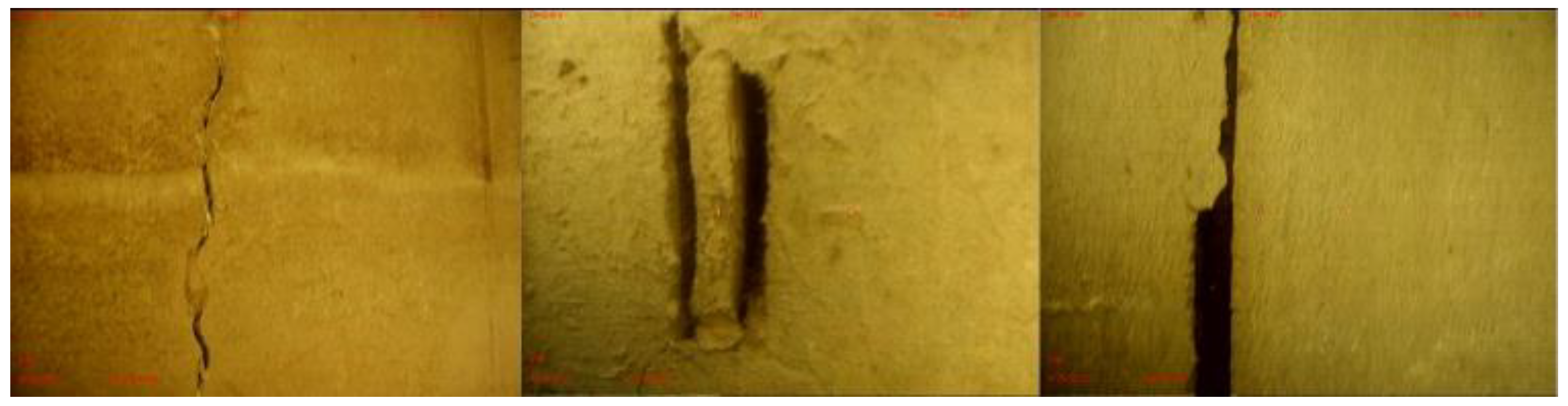
3.1.1. Underwater Dam Crack Images

The underwater concrete crack pictures come from the video taken by the ROVs in the process of crack detection. Part of the pictures in the video are captured. There are a total of 600 underwater concrete crack pictures, including irregular crack pictures with different degrees of cracking. The image is 704 × 480 pixels. Some images of an underwater dam concrete crack dataset are shown in Figure 9.

3.1.2. Concrete Crack Images for Classification [27]

The concrete crack dataset contains a total of 10,000 images of concrete surface cracks with different degrees of cracking. The surface cracks are divided into three categories: more cracked, moderately cracked and less cracked. Also included in the dataset images are various disturbances that may be encountered in realistic scenes, such as cigarette butts, dust, etc. The resolution of the dataset images is 227 × 227. A total of 600 images were selected from this dataset in a balanced manner according to different degrees of cracking. Some images of the dataset are shown in Figure 10.

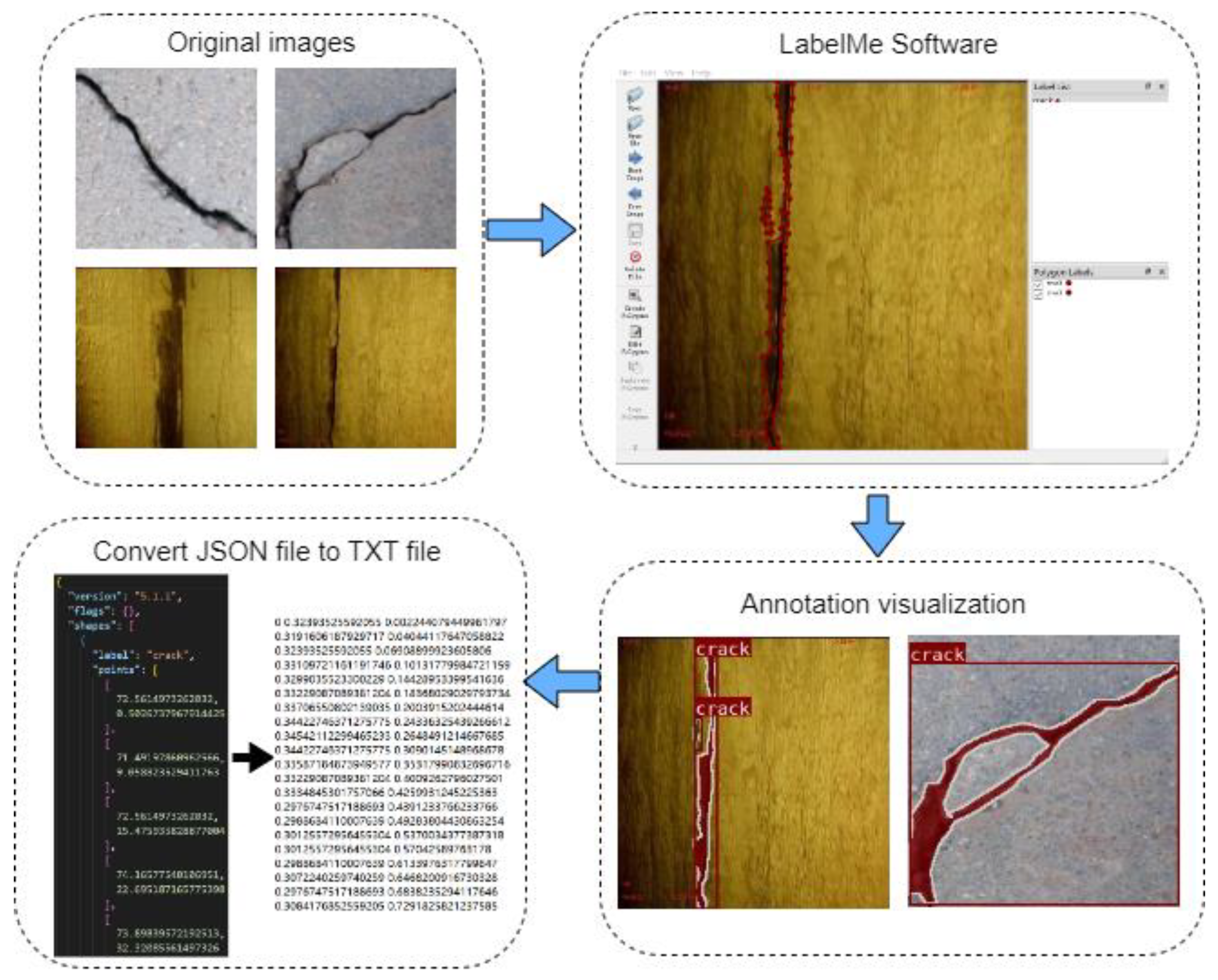
3.2. Data Pre-Processing and Data Augmentation

The locations of the cracks were manually labelled using the labelling software LabelMe (http://labelme.csail.mit.edu/Release3.0/) to form our training dataset. Figure 11 shows the pixel-level labelling process for the crack images. As observed from Figure 11, the crack area of the picture is marked using LabelMe software and saved as a JSON file. Then, the JSON file is converted to a TXT file via a program for model training.
To improve the diversity and richness of the data, several data augmentation strategies are utilized in the implementation, including: Moasic, augment HSV, random affine with 0.5 of scale ratio and 0.1 translation ratio and random horizontal flip with 50% probability. Meanwhile, the data augmentation is only applied during the model training phase, no data augmentation is used on the validation set. Figure 12 shows the images after data augmentation.

3.3. Implementation Details

The model was trained for 800 epochs with pre-trained weights until the model converged. The input image size is 448 × 448 , and the training batch size is 8. As with the hyperparameter settings of YOLOv8n-seg, we used an SGD optimiser with a momentum of 0.937 and a weight decay of 0.0005. For the learning rate, it was set to 0.001 for the first three warm-up cycles and then reached 0.01 and kept shrinking to 0.0001 until the last epoch.
All tests in this paper were finished on the NVIDIA RTX3090 GPU.

3.4. Evaluations Metrics

During the experiments in this paper, we used m A P 0.5 and m A P 0.5 0.95 to measure the box and mask accuracy of the model and inference time to measure the inference speed of the model. m A P 0.5 and m A P 0.5 0.95 can be described as:
m A P 0.5 = 1 n c 0 1 P ( R ) d R
m A P 0.5 0.95 = a v g ( m A P i ) , i = 0.5 : 0.05 : 0.95
where n c denotes the number of the classes, P represents precision and R represents the recall, and they satisfy:
P = T P T P + F P
R = T P T P + F N
where T P is true positive, which represents the number of the prediction boxes whose I o U > 0.5 ; F P is false positive, which represents the number of the prediction boxes whose I o U 0.5 ; and F N is false negative, which represents the number of the labels without prediction.
In addition, weights, parameters and GFLOPs were used to evaluate the complexity of the model.

3.5. Experimental Results

The curves of the performance of the model during the experiment are shown in Figure 13.
The final experimental results of our model are shown in Table 2. We used the same dataset on YOLOv8n-seg, YOLOv8s-seg, YOLOv8m-seg, YOLOv7-seg and Mask R-CNN as a comparison, and the experimental results are also shown in Table 2.
As can be seen from the Table 2, all models perform well for the crack detection task, and the larger the model size, the higher the detection accuracy. Compared with the large model, our model has obvious advantages in size and calculation. Our model achieves a large reduction in volume and calculation with a small performance reduction, which is friendly to low-performance devices. Compared with the baseline model YOLOv8n-seg, our model has a 3% drop in detection accuracy, a 39% drop in weight, a 40% drop in parameters and a 51% drop in GFLOPs. Our model has the obvious advantage of small size, while maintaining high crack detection accuracy, and has real-time detection capability.

3.6. Crack Detection Results

Four crack images with different crack degrees and different environments were input into our model to verify the crack detection performance. The surface crack detection results of our model are shown in Figure 14. Our model accurately identified the locations and shapes of the cracks in all four images and detected surface cracks of varying degrees with good results.

4. Comparative Experiment and Ablation Study

4.1. Comparison of Different Crack Detection Method

Three crack images were input into crack detection methods with different algorithms, and a comparison of the crack detection results of different algorithms is shown in Figure 15. The Canny edge detector is able to detect and display the edges of cracked and non-cracked areas, but its detection results are noisy and the detection speed is slow, so it is not suitable for real-time crack detection. The crack detection method based on object detection shows the confidence and labelling of the cracks and uses a target box to frame the entire crack, but does not depict the exact crack area. When the trajectory of the crack is tilted, the target box becomes large and its detection effect will appear weaker, such as in picture (a). Our method is able to display the confidence and labelling of the detected cracks, as well as being able to frame the cracks using a target box and depict the entire area of the crack at pixel level. It is clear that our method is better suited to the task of crack detection.

4.2. Comparison of Performance and Instance Mask of Different Prototype Branches

We respectively replaced the Proto module of YOLOv8n-seg and YOLOv8m-seg with ProtoC1 for comparison. The comparison of performance and instance mask is shown in this section.

4.2.1. Comparison of Performance of Different Proto Modules

As shown in the Table 3, after the YOLOv8m-seg model (using the standard Proto module with 256 channels of feature maps) used our proposed protoc1 structure, the GFLOPs of the model decreased by 18.8, a 17% decrease, while the m A P 0.5 of the mask decreased by 0.3%, almost no drop, and the m A P 0.5 0.95 of the mask decreased by 1.2%. With the smallest model YOLOv8n-seg using our proposed ProtoC1 structure, the model almost has the same performance, but the GFLOPs of the model decreased by 14%, and the model complexity is reduced. Compared with the Proto module used by YOLOv8n-seg (with 64 channels in the middle feature maps), our proposed ProtoC1 module reduces the depth and width of the network structure, which makes the prototype branch more lightweight.

4.2.2. Comparison of Instance Mask of Different Proto Modules

The ProtoC1 (k = 1) structure is able to further reduce the parameters and computation of the model, but in our experiments, we found that using a 2D convolution of kernel size 1 reduces the accuracy of the instance mask, the m A P 0.5 0.95 of the mask decreased 7.5%, so we discarded this structure and used this structure as a comparison.
The comparison of crack detection results of the YOLOv8n-seg model using the default Proto module, ProtoC1 module, and ProtoC1 (k = 1) module is shown in Figure 16. We can see that using the ProtoC1 (k = 1) structure results in roughness at the edges of the instance mask and a decrease in mask accuracy. The YOLOv8n-seg model using the ProtoC1 module generates an instance mask with smooth edges and the same mask accuracy as the Proto model, while our proposed ProtoC1 module is more lightweight.

4.3. Ablation Study

There are two improvement measures in our model, including: replacing the backbone with LCANet and replacing Proto with a ProtoC1 module. To verify the effect of these measures on our model, an ablation experiment is undertaken in this paper. The results of the ablation study are shown in Table 4. It can be observed from the experimental data that, by replacing the Proto module of YOLOv8n-seg with ProtoC1, the detection accuracy is almost the same, while the model complexity and computation are reduced. By replacing the backbone of YOLOv8n-seg with LCANet, since LCANet uses 10 dblocks and reduces the channels of feature maps, the detection accuracy of the model is reduced by 3% and the layers of the model are increased by 15, while the GFLOPs of the model are reduced by 4.6, which is 37%, and the weights and parameters of the model are also greatly reduced. Compared with the baseline model YOLOv8n-seg, our model reduces the detection accuracy by 3% but greatly reduces the model volume, which is friendly to low-performance devices. Furthermore, the introduction of transfer learning (TL) reduces the model training cost and enhances its robustness, resulting in a slight increase in model detection accuracy.

5. Conclusions

Accurate identification and quantification of cracks is important for understanding structural damage in dam and bridge structures. This study proposes a pixel-level real-time crack segmentation method based on the LCA-YOLOv8-seg model. A lightweight LCANet backbone and a more lightweight prototype mask branch are proposed to reduce the model complexity. A new lightweight prototype mask branch, ProtoC1, speeds up the prototype mask branch while maintaining the quality of instance masks. Our method achieves 0.945 m A P 0.5 and 129 FPS on the concrete surface crack dataset, and our model has significant advantages over YOLOv8n-seg in terms of weights, parameters and GFLOPs. This shows that our model has good accuracy and real-time detection capability and light volume, making it a practical algorithm for crack detection. In future research, we will continue to optimize the size and accuracy of the model while expanding the dataset and increasing the robustness of the model.

Author Contributions

Conceptualization, Q.H. and Y.W.; writing—original draft preparation, Y.W.; methodology, Y.W.; software, Q.J. writing—review and editing, Q.H. and J.L.; visualization, Y.Z.; resources, Q.J. and J.L. All authors have read and agreed to the published version of the manuscript.

Funding

This research was funded by the Natural Science foundation of China, grant numbers 12174085 and 12274113.

Institutional Review Board Statement

Not applicable.

Informed Consent Statement

Not applicable.

Data Availability Statement

The data presented in this study are available on request from the corresponding author.

Conflicts of Interest

The authors declare no conflict of interest.

References

  1. Stricker, R.; Eisenbach, M.; Sesselmann, M.; Debes, K.; Gross, H.-M. Improving visual road condition assessment by extensive experiments on the extended gaps dataset. In Proceedings of the International Joint Conference on Neural Networks (IJCNN), Budapest, Hungary, 14–19 July 2019; pp. 1–8. [Google Scholar] [CrossRef]
  2. Li, Z. Global sensitivity analysis of the static performance of concrete gravity dam from the viewpoint of structural health monitoring. Arch. Comput. Methods Eng. 2021, 28, 1611–1646. [Google Scholar] [CrossRef]
  3. Xiang, Y.; Sheng, J.; Wang, L.; Cai, Y.; Meng, Y.; Cai, W. Research progresses on equipment technologies used in safety inspection, repair, and reinforcement for deepwater dams. Sci. China Technol. Sci. 2022, 65, 1059–1071. [Google Scholar] [CrossRef]
  4. Tan, Y.; Li, S.; Liu, H.; Chen, P.; Zhou, Z. Automatic inspection data collection of building surface based on BIM and UAV. Autom. Constr. 2021, 131, 103881. [Google Scholar] [CrossRef]
  5. Lund-Hansen, L.C.; Juul, T.; Eskildsen, T.D.; Hawes, I.; Sorrell, B.; Melvad, C.; Hancke, K. A low-cost remotely operated vehicle (ROV) with an optical positioning system for under-ice measurements and sampling. Cold Reg. Sci. Technol. 2018, 151, 148–155. [Google Scholar] [CrossRef]
  6. Capocci, R.; Dooly, G.; Omerdić, E.; Coleman, J.; Newe, T.; Toal, D. Inspection-class remotely operated vehicles—A review. J. Mar. Sci. Eng. 2017, 5, 13. [Google Scholar] [CrossRef]
  7. Kheradmandi, N.; Mehranfar, V. A critical review and comparative study on image segmentation-based techniques for pavement crack detection. Constr. Build. Mater. 2022, 321, 126162. [Google Scholar] [CrossRef]
  8. Wang, C.-Y.; Bochkovskiy, A.; Liao, H.-Y.M. YOLOv7: Trainable bag-of-freebies sets new state-of-the-art for real-time object detectors. In Proceedings of the IEEE/CVF Conference on Computer Vision and Pattern Recognition, Seattle, WA, USA, 13–19 June 2020; pp. 7464–7475. [Google Scholar] [CrossRef]
  9. Qin, X.; Zhang, Z.; Huang, C.; Dehghan, M.; Zaiane, O.R.; Jagersand, M. U2-Net: Going deeper with nested U-structure for salient object detection. Pattern Recognit. 2020, 106, 107404. [Google Scholar] [CrossRef]
  10. Li, F.; Zhang, H.; Xu, H.; Liu, S.; Zhang, L.; Ni, L.M.; Shum, H.-Y. Mask dino: Towards a unified transformer-based framework for object detection and segmentation. In Proceedings of the IEEE/CVF Conference on Computer Vision and Pattern Recognition, Vancouver, BC, Canada, 17–24 June 2023; pp. 3041–3050. [Google Scholar] [CrossRef]
  11. Chen, H.; Sun, K.; Tian, Z.; Shen, C.; Huang, Y.; Yan, Y. Blendmask: Top-down meets bottom-up for instance segmentation. In Proceedings of the IEEE/CVF Conference on Computer Vision and Pattern Recognition, Seattle, WA, USA, 13–19 June 2020; pp. 8573–8581. [Google Scholar] [CrossRef]
  12. Cardellicchio, A.; Ruggieri, S.; Nettis, A.; Renò, V.; Uva, G. Physical interpretation of machine learning-based recognition of defects for the risk management of existing bridge heritage. Eng. Fail. Anal. 2023, 149, 107237. [Google Scholar] [CrossRef]
  13. Cardellicchio, A.; Ruggieri, S.; Nettis, A.; Mosca, N.; Uva, G.; Renò, V. On the use of YOLOv5 for detecting common defects on existing RC bridges. In Proceedings of the Multimodal Sensing and Artificial Intelligence: Technologies and Applications III, Munich, Germany, 26–30 June 2023; pp. 134–141. [Google Scholar] [CrossRef]
  14. Uzar, M.; Öztürk, Ş.; Bayrak, O.C.; Arda, T.; Öcalan, N.T. Performance analysis of YOLO versions for automatic vehicle detection from UAV images. Adv. Remote Sens. 2021, 1, 16–30. [Google Scholar]
  15. Bayramoğlu, Z.; Melis, U. Performance analysis of rule-based classification and deep learning method for automatic road extraction. Int. J. Eng. Geosci. 2023, 8, 83–97. [Google Scholar] [CrossRef]
  16. Zhang, Q.; Barri, K.; Babanajad, S.K.; Alavi, A.H. Real-time detection of cracks on concrete bridge decks using deep learning in the frequency domain. Engineering 2021, 7, 1786–1796. [Google Scholar] [CrossRef]
  17. Wang, W.; Su, C. Semi-supervised semantic segmentation network for surface crack detection. Autom. Constr. 2021, 128, 103786. [Google Scholar] [CrossRef]
  18. Xiang, X.; Wang, Z.; Qiao, Y. An improved YOLOv5 crack detection method combined with transformer. IEEE Sens. J. 2022, 22, 14328–14335. [Google Scholar] [CrossRef]
  19. Zhou, Z.; Zhang, J.; Gong, C. Automatic detection method of tunnel lining multi-defects via an enhanced You Only Look Once network. Comput. Aided Civ. Infrastruct. Eng. 2022, 37, 762–780. [Google Scholar] [CrossRef]
  20. Dosovitskiy, A.; Beyer, L.; Kolesnikov, A.; Weissenborn, D.; Zhai, X.; Unterthiner, T.; Dehghani, M.; Minderer, M.; Heigold, G.; Gelly, S. An image is worth 16x16 words: Transformers for image recognition at scale. arXiv 2020, arXiv:2010.11929. [Google Scholar] [CrossRef]
  21. Zhang, J.; Qian, S.; Tan, C. Automated bridge surface crack detection and segmentation using computer vision-based deep learning model. Eng. Appl. Artif. Intell. 2022, 115, 105225. [Google Scholar] [CrossRef]
  22. Xu, X.; Zhao, M.; Shi, P.; Ren, R.; He, X.; Wei, X.; Yang, H. Crack detection and comparison study based on faster R-CNN and mask R-CNN. Sensors 2022, 22, 1215. [Google Scholar] [CrossRef] [PubMed]
  23. He, K.; Gkioxari, G.; Dollár, P.; Girshick, R. Mask r-cnn. In Proceedings of the IEEE International Conference on Computer Vision, Venice, Italy, 22–29 October 2017; pp. 2961–2969. [Google Scholar] [CrossRef]
  24. Wang, Q.; Wu, B.; Zhu, P.; Li, P.; Zuo, W.; Hu, Q. ECA-Net: Efficient channel attention for deep convolutional neural networks. In Proceedings of the IEEE/CVF Conference on Computer Vision and Pattern Recognition, Seattle, WA, USA, 13–19 June 2020; pp. 11534–11542. [Google Scholar] [CrossRef]
  25. Ultralytics YOLOV8. Available online: https://github.com/ultralytics/ultralytics (accessed on 5 September 2023).
  26. Bolya, D.; Zhou, C.; Xiao, F.; Lee, Y.J. Yolact: Real-time instance segmentation. In Proceedings of the IEEE/CVF International Conference on Computer Vision, Seoul, Republic of Korea, 27 October–2 November 2019; pp. 9157–9166. [Google Scholar] [CrossRef]
  27. Concrete Crack Images for Classification. Available online: https://data.mendeley.com/datasets/5y9wdsg2zt/2 (accessed on 5 September 2023).
Figure 1. A remotely operated vehicle (ROV).
Applsci 13 10583 g001
Figure 2. The framework of the proposed method.
Applsci 13 10583 g002
Figure 3. The structure of LCA-YOLOv8n-seg.
Applsci 13 10583 g003
Figure 4. The structure of DWConv block.
Applsci 13 10583 g004
Figure 5. The implementation of standard convolution.
Applsci 13 10583 g005
Figure 6. The implementation of depthwise separable convolution.
Applsci 13 10583 g006
Figure 7. The specific structure of standard Proto and ProtoC1. (a) The specific structure of standard Proto; (b) the specific structure of ProtoC1.
Applsci 13 10583 g007
Figure 8. The flowchart of the TL method.
Applsci 13 10583 g008
Figure 9. Examples of underwater dam concrete crack.
Applsci 13 10583 g009
Figure 10. Examples of crack images.
Applsci 13 10583 g010
Figure 11. Flowchart of the labelling process.
Applsci 13 10583 g011
Figure 12. Example images of data augmentation.
Applsci 13 10583 g012
Figure 13. Curves for the precision metric and m A P 0.5 metric of the training. (a) The curve of box precision and m A P 0.5 ; (b) the curve of mask precision and m A P 0.5 .
Applsci 13 10583 g013
Figure 14. Crack detection performance of our model. (ad) are crack pictures with different background and different crack size.
Applsci 13 10583 g014
Figure 15. Comparison of crack detection results of different algorithms. (ac) are different crack pictures.
Applsci 13 10583 g015
Figure 16. Comparison of crack detection mask of YOLOv8n-seg model using different Proto modules. (a,b) are crack pictures with different crack shape.
Applsci 13 10583 g016
Table 1. The specification for LCANet. The dblock is DWConv block. RE means RELU function.
ModuleInputOutputMidksNL
Conv38-32RE
dblock881232RE
dblock8125432RE
dblock12126631RE
dblock12247252RE
dblock242418051RE
dblock24249051RE
dblock242410851RE
dblock244821652RE
dblock484843251RE
dblock484843251RE
Table 2. Experimental results of different models.
ModelWeightParametersGFLOPs m A P 0.5 b o x m A P 0.5 m a s k FPS
YOLOv8n-seg7.15 M3409 K12.40.9740.967125
YOLOv8s-seg23.62 M11,863 K41.90.9920.989113
YOLOv8m-seg56.83 M27,286 K109.60.9970.99592
YOLOv7-seg72.58 M37,847 K1490.9980.99756
Mask R-CNN169.45 M43,970 K1340.9960.99839
LCA-Yolov8-seg4.36 M2045 K6.10.9450.933129
In Table 1, the best result of each evaluation metrics is bolded.
Table 3. The comparison of YOLOv8n-seg and YOLOv8m-seg model using different Proto modules.
ModuleLayerWeightParametersGFLOPs m A P 0.5 m a s k m A P 0.5 0.95 m a s k
YOLOv8m-seg(Proto)33141.82 M27,286 K109.60.9950.785
+ProtoC132540.51 M26,671 K90.80.9930.778
YOLOv8n-seg(Proto)2617.15 M3409 K12.40.9670.716
+ProtoC12557.04 M3352 K10.70.9660.713
+ProtoC1(k = 1)2557.01 M3336 K9.90.9280.638
Table 4. The experiment result of ablation study.
ModuleLayersWeightParametersGFLOPs m A P 0.5 b o x m A P 0.5 m a s k FPS
YOLOv8n-seg2617.15 M3409 K12.40.9740.967125
+ProtoC12557.04 M3352 K10.70.9740.966125
+LCANet2764.48 M2113 K7.80.9430.932128
LCA-YOLOv8-seg2704.36 M2045 K6.10.9420.929129
+TL2704.36 M2045 K6.10.9450.933129
Disclaimer/Publisher’s Note: The statements, opinions and data contained in all publications are solely those of the individual author(s) and contributor(s) and not of MDPI and/or the editor(s). MDPI and/or the editor(s) disclaim responsibility for any injury to people or property resulting from any ideas, methods, instructions or products referred to in the content.

