1. Introduction
Urban traffic problems have become more serious with the continuous expansion of cities and rapid population growth. In this regard, the construction of subways is an effective measure to alleviate traffic congestion. A previous specification [
1] stipulated that a contact channel should be set up when the continuous length between two single-track running tunnels of urban rail transit is longer than 600 m. At present, the methods of contact channel construction include the open excavation method, the freezing method [
2], and the emerging mechanical method [
3,
4]. The open excavation method is relatively simple, but it is generally suitable for areas with good geological conditions, stable soil, and no heavy load around. The freezing method is used to excavate soil with a high water content after freezing, which has the advantages of causing less pollution and not being affected by the surrounding environment. However, it needs high technical requirements for construction, and will cause large surface settlement. The mechanical method, compared with the above two methods, has the advantages of a higher degree of mechanization, shorter construction period, safer construction, and smaller ground surface settlement. Mechanical connection channels have been applied in underground projects at home and abroad, which have unveiled its broad application prospects. These projects include the safety corridors of the Fourth Elbe River Tunnel in Hamburg, Germany, the brunch lines of the Emisor Oriente Tunnel in Mexico, and the rail transits in Ningbo [
5,
6], Wuxi [
7], Hangzhou [
8,
9], and Beijing [
10].
Some scholars carried out research on the construction, design, and calculation method for mechanical contact channel technology. Zhu et al. [
3] led the development of the engineering practice for mechanical connection channels in China and put forward a new construction concept characterized by “micro-reinforcement, machinable, tight sealing and strong supporting”, and expounded the cutting method and matters needing attention. Liu et al. [
4] studied the initial process of the mechanized drilling of contact tunnels through two full-scale tests and found that tunnel segments, together with the internal supports, carry the additional loads resulting from the cutting process. Meanwhile, other experts studied the security issue of mechanical connection channels under train loads and seismic loads using the finite element method and concluded that joints are prone to fatigue damage under dynamic loads [
11,
12]. Zhang et al. [
13,
14] took the practical application of a mechanical contact channel in a coastal area as the background, evaluated the construction safety, and verified the applicability of mechanical contact channel construction in a high-water-pressure mudstone stratum by numerical simulation. In recent years, it has been found in engineering practice that steel-ring secondary lining composite segments should be used at connecting positions to ensure a good seal between the contact channel and the main tunnel, but its deformation law in the cutting process has not been extensively studied yet [
15]. This is because steel-ring secondary lining composite segments are of great significance for both the safety of cutting construction and the long-term stability of the main tunnel and the contact channel. Accordingly, studies on the stress and deformation of steel-ring secondary lining composite segments in main tunnels have become extremely significant in the design and construction of mechanical connection channels.
At present, the research on the application and mechanical properties of steel-ring secondary lining structures in tunnels is relatively simple [
16,
17,
18,
19], and studies on the special positions of tunnels are especially lacking. In a previous study, Hirosawa et al. [
20] conducted bending and thrust tests on two kinds of concrete-filled composite segments. They obtained the mechanical characteristics of the steel–concrete composite segment and then put forward guiding suggestions for the design of concrete-filled composite segments in engineering practice. Meanwhile, Liao et al. [
21] evaluated the design theory of fiber-reinforced composite segments and optimized the structural design of steel–concrete composite segments, making them more suitable for practical engineering applications.
However, there is still a lack of research on the stress and deformation of steel-ring secondary lining composite segments under the construction conditions of mechanical connection channels. In addition, the applicability of the mechanical connection channel construction technology in the Beijing subway has not yet been checked. Thus, a full-scale model test is conducted in this paper to study the influence of the cutting construction of contact channels on the stress and deformation of the tunnel structure. The impact of steel–concrete composite segments on the cutting construction is evaluated for Beijing Metro Line 19.
The above-mentioned related research has made some achievements in the mechanical properties and design application of steel-ring lining composite segments. However, the research on the stress and deformation of the contact channel during shield cutting using a large model test is lacking. In addition, the mechanical construction technology of the contact channel is used in soft-soil areas, where the soil strength is weak, and the stress of tunnel segments is different in different soil strengths, so its applicability in areas with strong soil strength still needs to be checked. Based on the application background of the mechanical connecting passage of Beijing Rail Transit Line 19, this paper studies the tunnel structural response during the cutting construction of the contact channel through the full-scale model test platform. Additionally, the influence of the steel-ring lining composite segment on the cutting construction is also studied, so as to provide guidance for the subsequent application of this technology in Beijing Rail Transit.
2. Test Scheme
2.1. Test Object
The shield section of Beijing Metro Line 19 starts at the south side of Qinghe River and ends at Xiaoying West Road. The mechanical method is proposed for the construction of three connection channels in this project. The soil layers that the connection channels cross are mainly silty clay, clayey silt, sandy silt, sandy soil, and pebble gravel layers. Through geological and hydrogeological investigations, it was found that the existing mechanical method of connection channel construction technology could not be directly applied in this project. The main reason is that the communication channel construction technology is developed for coastal soft-soil areas. The earth pressure and formation resistance are different in different geological conditions, which further affects the construction safety. In this regard, a full-scale model test for connection channel construction with typical geological conditions in Beijing was conducted.
Given the condition of the test platform, the engineering tunnel structure was simplified as illustrated in
Figure 1. The structural system included the segment of the cutting position and the segment of the main influence area of the cutting construction, which had seven rings in total. Each ring segment consisted of a cap block (F), adjacent blocks (L1 and L2), and standard blocks (B1, B2, and B3). The whole-environment, full-scale test model had the same size and assembly method as those of the actual segments, of which the middle three rings (the fourth ring is called the cutting ring; the third and fifth rings are called the half-cutting rings) were assembled with a straight joint with a ring width of 1500 mm. The other four rings (also called standard rings) were assembled with staggered joints with a ring width of 1200 mm. The segment had an outer diameter of 6200 mm, an inner diameter of 5500 mm, and a ring thickness of 350 mm. The two special-position segments of the middle three rings (B1 and B3) were steel-ring, double-lined composite segments composed of steel liners, fiber bars, and concrete.
2.2. Test Platform
The full-scale test relied on the comprehensive test platform of Ningbo University. The basic components of the platform included a modular soil pressure simulation device, modular support base, foundation simulation device, tunnel segment longitudinal loading simulation device, multi-ring segment tunnel test unit assembly and transportation device, multi-ring segment tunnel test unit lifting device, and connecting channel shield-tunneling machine receiving simulation device. The platform can conduct 1:1 physical model tests of shield-tunneling construction, which truly simulate and test the bearing capacity of the segment lining structures under normal load and ultimate load, the mechanical transmission between rings, and other mechanical properties. Additionally, the platform can also simulate the construction progress of mechanical connection channels to study the influence of the cutting process on the main channel structures.
The loading system of the test platform adopted a steel counter-stress frame connected by a seven-ring flange as the main body, and the loading was assisted by 24 oil cylinders per ring. There were 168 oil cylinders in total, as shown in
Figure 2. The displacement accuracy of the oil cylinder is 0.1 mm, which can realize three control modes: load control, displacement control, and load–displacement control. From this, the actual resistance of soil layers can be simulated accurately.
2.3. Monitoring Scheme
For studying the stress and deformation law of the tunnel segment structure, the convergence deformation and stress change of the segment structure were monitored by laying a pull-line displacement meter and a strain gauge, respectively. A total of 15 pull-line displacement meters were arranged at 0°, 90°, and 270° of the tunnel segment, with each ring having three pull-line displacement meters.
Figure 3 shows the installation conditions.
Figure 4 shows the layout scheme of the measuring points of the steel strain gauges for the tunnel segments.
Figure 4a shows the standard ring segment condition, where 13 test sections are selected for arranging steel strain gauges, and 104 strain gauges are applied in total.
Figure 4b shows the cutting ring segment condition, where 9 test sections are selected, and 72 strain gauges are applied in total. In these figures, take N2-1 as an example. N stands for the steel bar strain gauge, 2 stands for the second ring, and 1 stands for the first strain gauge of the ring.
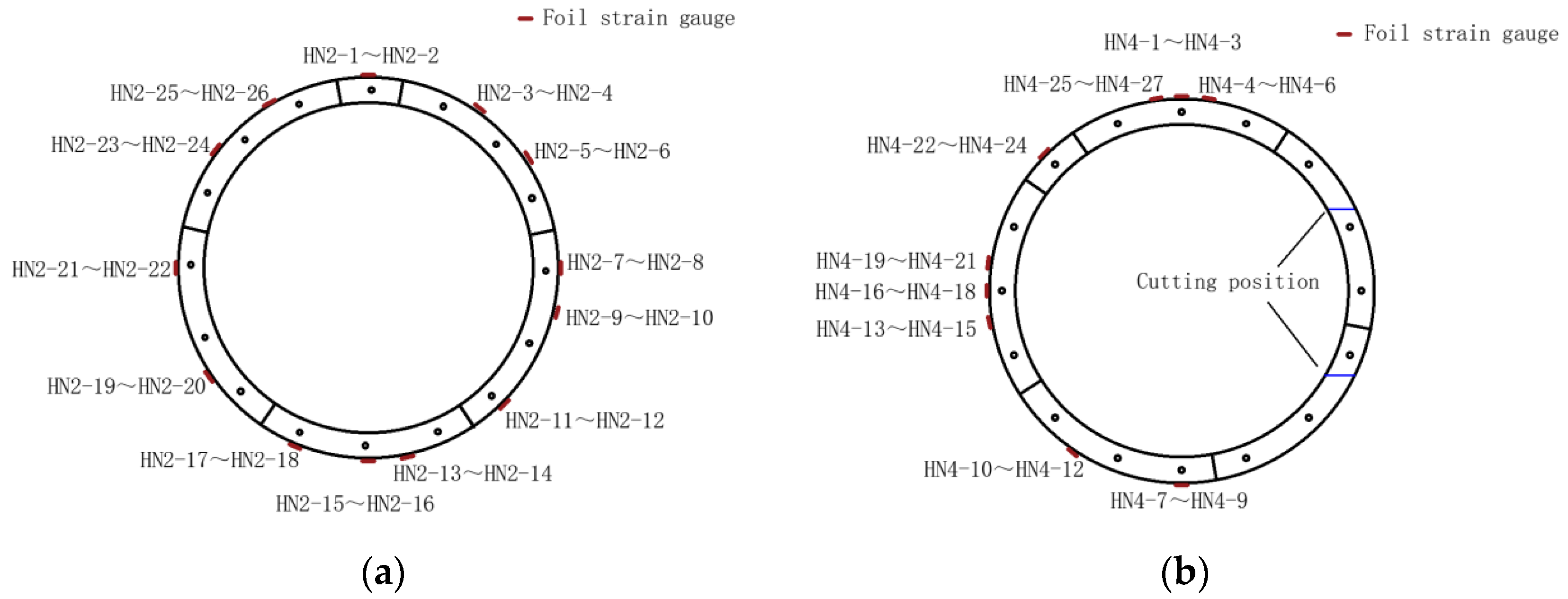
Figure 5 shows the layout scheme of the measuring points of the concrete strain gauges for the tunnel segments.
Figure 5a shows the standard ring segment condition, where 13 test sections are also selected to arrange the concrete strain gauges along the outer curved surface, and 26 strain gauges are applied in total.
Figure 5b shows the condition of the cutting ring segments, where 9 test sections are selected, and 27 strain gauges are applied in total. In these figures, with HN2-5 as an example, HN stands for the concrete strain gauge, 2 stands for the second ring, and 5 stands for the fifth strain gauge of the ring.
The aggregation of monitoring contents and monitoring sensors are listed in
Table 1.
2.4. Test Conditions
(1) Initial condition
Based on the engineering design data and geological conditions, the earth pressure at different positions of the tunnel structure was calculated and simulated by oil cylinder loading. The positions of cylinders are shown in
Figure 2 (24 cylinders), and the loading schemes of each cylinder are shown in
Table 2 and
Table 3. The 24 cylinders in each ring were controlled to load in the original round state first. Then, the displacement of the lower oil cylinders No. 19–24 was locked, and the other oil cylinders were controlled by load. The soil pressures were gradually loaded to the designed value in 10 stages. Thereafter, the load control mode of cylinders No. 7–12 in the top range remained unchanged, and the control modes of oil cylinders No. 1–6 and No. 13–18 were switched to load–displacement curve control. The test was conducted step by step. Starting from the second loading step, each step was loaded after the stress and deformation of the upper stage were stabilized. The loading conditions of the standard and cutting rings in each oil cylinder are shown in
Table 2 and
Table 3, respectively.
(2) Adding internal support condition
In the adding internal support condition, an internal support system was simulated in the tunnel to provide support to the segments. First, the supports of the top, bottom, and waist parts were stretched horizontally and longitudinally to ensure the three parts reached the inner surface of the tunnel. Then, the oil cylinders were loaded to add internal support to the tunnel. Second, with the displacement of the waist supports unchanged, the top supports were loaded in stages with a small load and locked after reaching a certain pressure value. Third, the waist supports were loaded step by step under a small load and locked after reaching a certain pressure value. The above operations were repeated until the supporting stress reached the required pre-supporting stress before this working condition was finished. A sketch of the internal support system is shown in
Figure 6.
(3) Cutting construction condition
The cutting condition simulated the influence of internal segment cutting on the steel rings, secondary lining composite segments, and adjacent segments. In this condition, the external loading modes of the segments were kept unchanged. Additionally, the load values and load control modes of oil cylinders No. 7−12 as well as the load value and the load−displacement curve control mode of oil cylinders No. 1−6 and No. 13−18 remained unchanged.
(4) Dismantling internal support condition
The dismantling of the internal support simulated the influence of the internal support system on the segment structure of the main tunnel after dismantling. First, the internal supports were dismantled after all the external loads had remained stable for some time. Then, keeping the load of oil cylinders No. 7−12 unchanged, oil cylinders No. 1−6 and No. 13−18 remained controlled by the load–displacement curve. Later, the control steps were reduced step by step, with the next loading step being conducted after each step to ensure the stability of the load and displacement until the end of the support dismantling.
3. Deformation Results and Analysis
Figure 7 shows the test results of the segment convergence deformation under the initial condition. The figure shows that each ring segment was elliptically deformed under the initial condition. The convergence deformation of the top and waist positions increased step by step with the loading step. It had a linear relationship with the number of stages and increased by about 1.5 mm under each stage of loading. After the initial condition (ten−level loading), the segment convergent deformation had a certain rebound, and the convergence deformation of the top and waist positions of each ring segment was maintained at about 15 mm (the segment was still in the elastic stage). Under the initial condition, the inward convergence deformation of the top position of each ring segment was consistent with the extrusion deformation of the waist position, indicating that the load−displacement control loading scheme could simulate the mechanical characteristics of the tunnel segment in actual soil layers.
Figure 8 shows the test results of the segment convergence deformation under the adding internal support condition. The figure shows that because of the erection of the internal support system in the tunnel under the working condition, the pre−supported structure influenced the convergence deformation of the top-position segment. When the top support and the front and rear supports of the waist approached the segment and were loaded step by step, the convergence deformation of the top-position segment decreased by about 1 mm, and the force at the top position was 800 kN. Afterward, with the increase in the loading of the internal support, the convergence deformation of the top and waist positions of the segment was not obvious. In the later stage, when the force at the top position gradually increased to the test set point, the displacement of each ring segment was reduced by about 1−2 mm again, and the change was basically linear. Because the waist position of the middle three rings adopted the steel-ring secondary lining composite segment, the convergence deformation change of the waist position was smaller than that of the top position, indicating that the pre−supporting force at the waist position had less influence on the composite segment.
Figure 9 shows the test results of the segment convergence deformation under the cutting condition. The figure shows that under the cutting condition, the change in the convergence deformation of the top position in the initial stage was small, and the change for each ring was about 1 mm. Thereafter, during the cutting process, the front and rear support forces at the waist position were kept unchanged, the thrust of the shield machine was stable at 1700 kN, and the unloading effect on the top-position support was performed within a small control range. At this time, the convergence deformation of the top-position segment increased by about 1−2 mm, but the latter remained basically stable. Because the segment at the cutting position was not constrained by longitudinal and circumferential bolts, from the time when the cutter head of the shield machine started cutting to the time when the cutter head wore the hole, a large dislocation occurred outward, and an obvious convergence deformation change occurred. Therefore, under the cutting condition, the waist position at the opening side had a significantly larger convergence deformation than that of the waist position at the back side, and the convergence deformation of the third and fourth cutting rings was about 250 mm, indicating that the steel-ring secondary lining composite segment at the waist position was controlled by the side of the hole.
Figure 10 shows the results of the convergence deformation test of the segment under the dismantling condition. The figure shows that in the dismantling of the internal support, the convergence deformation of each ring segment increased according to the increase in the unloading series of the internal support. Finally, the displacement of the top and waist positions of the segment increased by about 2−3 mm. During the whole dismantling process, the convergence deformation of the top of the middle third ring was relatively stable, and the convergence of the waist changed obviously. This was because the internal support system played a significant role in supporting the segment in the tunnel during the construction. When the internal support system was gradually unloaded and dismantled, the waist of the cutting ring lost its structural integrity due to construction and other factors, which resulted in a relatively large deformation.
Figure 11 shows the overall convergence deformation test results of the five−ring segment under different working conditions. The figure shows that the convergence deformation at the top of the middle three−ring segment was slightly larger than that at the top of both sides, and the convergence deformation of the top position of each ring was relatively consistent under different working conditions. The convergence deformation of the waist position of each ring was relatively consistent under different working conditions. Because of the cutting effect of the steel-ring secondary lining composite segment, the resulting convergence deformation was larger than that of the standard ring. During the cutting process, the oscillation caused by the thrust of the shield machine oil cylinder and the cutting of the segment greatly influenced the whole segment, and the convergence deformation of the top and waist positions increased by about 2−4 mm. Because of the erection of the internal support system, the whole ring segment was well supported, and the convergence deformation of the segment was buffered; thus, the convergence deformation was basically stable.
Table 4 shows the comparison of the convergence deformations of the segment under the initial and dismantling conditions. The table shows that the maximum convergence deformations of the top and waist positions of the segment did not exceed 20 and 30 mm, respectively, which were about four-thousandths that of the entire ring, meeting the requirements of the serviceability limit states (30 mm).
5. Structural Internal Force Analysis
According to the strain monitoring of each measuring point, it can be considered that the reinforcing bars of the lining structure are in an elastic state. Accordingly, the axial force N and bending moment M of the section can be calculated according to the following formulas [
3]:
where
εs and
εs′ are the inner and outer reinforcement strains, respectively;
As and
As′ are the inner and outer reinforcement areas, respectively;
Es and
Es′ are the inner and outer reinforcement elastic modules, respectively;
h,
b, and
c are the segment thickness, ring width, and protection layer thickness, respectively;
ε(
x) represents the concrete strain at the corresponding position;
σ(
x) represents the concrete stress determined by the concrete strain at the corresponding position.
The three-ring segment in the middle of the tunnel structure was selected as the research object. The axial force
N and bending moment
M of each test section under the four conditions were calculated and analyzed, as shown in
Figure 18 and
Figure 19, respectively.
Figure 18 shows that the internal force of the segment was redistributed after the end of the test condition and the axial force of each ring segment decreased overall. The axial force of the section near the inversion point of the cutting ring structure decreased first and then increased, and its change fluctuated greatly. The axial force at the upper spandrel position on the cutting side of the half-cutting ring increased significantly, whereas the axial force at the cross-section position near the inflection point of the structure decreased significantly. Considering the deformation and axial force variation (no more than 1000 kN) of the segment, the overall tunnel structure was in a safe state.
Figure 19 is a graph of the bending moment change. This figure shows that after the end of the test condition, the bending moments at the same test section position of each ring were basically the same. The tension and compression of the concave surface at the top and waist positions of the segment increased compared with those in the initial condition. At the position of the upper spandrel on the cutting side of the middle three rings, the bending moment decreased significantly with the cutting process. The variation was 200 kN m. The bending moment of the section near the contraflexure point of the structure changed significantly during the dismantling stage (from compression to tension). Comparing the same test sections of the cutting ring and the semi−cutting ring, the bending moment transmission between the rings was obvious, which was beneficial to the stress of the structure. During the cutting condition, the bending moment of each ring segment decreased and the axial force increased. This was beneficial to the stability of the main tunnel segment structure.
6. Conclusions
In this paper, a full-scale model test of the mechanical connection channel was conducted for the Beijing Rail Transit project. The internal force and deformation laws of the tunnel structure were studied under load–displacement simulation loading control and ground resistance. The main conclusions are as follows:
(1) In terms of the convergence deformation of the segment structure, the top and waist positions of each ring performed relatively consistently, with the maximum convergence of the top not exceeding 20 mm and the maximum convergence of the waist not exceeding 30 mm. In addition, the variation at the top of the middle three rings was small, whereas the convergence deformation of the waist position of the steel-ring secondary lining composite segment was larger than that of standard rings in the cutting construction.
(2) In terms of the strain and internal force of the segment structure, the internal force of each ring was redistributed and the axial force decreased overall during the cutting process. The bending moment at the upper spandrel position in the cutting side of the middle three rings decreased significantly with the cutting construction, and the decrement of the bending moment was larger than that of the corresponding axial force. This benefited the stability of the structure. Additionally, the section bending moment near the contraflexure point of the middle three rings changed significantly with the internal support-dismantling process, and it changed from compression to tension conditions. It has been proven that there was a significant bending moment transmission between rings, which also favored the structure stability.
(3) On the basis of the connection channel full-scale model test, it can be concluded that the mechanical method can be safely and reliably applied in the Beijing Metro construction. Additionally, compared with the existing design schemes of mechanical connection channels, the stiffness of the segment structure and support structure at the cutting position can be weakened, and the stiffness of the steel-ring secondary lining composite segment can be decreased.


