Article

Chirped-Pulse Amplification in an Echo-Enabled Harmonic-Generation Free-Electron Laser

1
Institute of Advanced Science Facilities, Shenzhen 518107, China
2
Dalian Institute of Chemical Physics, CAS, Dalian 116023, China
3
College of Science, Southern University of Science and Technology, Shenzhen 518055, China
*
Authors to whom correspondence should be addressed.
Appl. Sci. 2023, 13(18), 10292; https://doi.org/10.3390/app131810292
Submission received: 8 August 2023 / Revised: 25 August 2023 / Accepted: 29 August 2023 / Published: 14 September 2023
(This article belongs to the Special Issue Recent Advances in Ultrafast Laser Pulses)

Abstract

:
The field of ultrafast science has experienced significant growth over the last decade, largely attributed to advancements in optical and laser technologies such as chirped-pulse amplification and high-harmonic generation. The distinctive characteristics of intense ultrafast free-electron lasers (FELs) have introduced novel prospects for investigating molecular dynamics, as well as providing an opportunity to gain deeper insights into nonlinear processes in materials. Therefore, high-power ultrafast FELs can be widely used for both fundamental research and practical applications. This study presents a novel approach for producing high-power femtosecond FEL pulses, utilizing chirped-pulse amplification in echo-enabled harmonic generation. Chirped seed pulses are employed to induce frequency-chirped energy modulation in the electron beam. The generated FEL pulse, which inherits the chirped frequency, can be compressed through the gratings in the off-plane mount geometry to provide ultraintense ultrafast pulses. The numerical modeling results indicate that peak power exceeding 20 GW and a pulse duration in the order of several femtoseconds can be achieved.

1. Introduction

High-power and ultrafast free-electron lasers (FELs) have become an indispensable tool across a multitude of scientific disciplines, including physics, chemistry, biology, and so on [1,2,3,4]. The shorter pulse duration leads to better temporal resolution in pump-probe experiments. Taking single-particle imaging as an example, the use of ultrafast photon pulses is necessary to prevent any alterations to the sample’s structure during the probe pulse duration [5]. Specifically, achieving subnanometer resolution requires photon pulses with durations of less than 10 fs. High-power FEL pulses facilitate the exploration of nonlinear phenomena arising from their interaction with atoms and molecules [6]. Experiments, such as stimulated Raman scattering [7], are heavily reliant on the available peak intensity of the photon pulses. As indicated in [7], a three-fold increase in the incoming FEL peak power can result in a four-order-of-magnitude rise in the emission signal. Therefore, the generation of high-power and ultrafast FEL pulses is a critical necessity in numerous FEL experiments.
To shorten the time duration of FEL pulses, several approaches have been proposed and developed recently [8,9,10,11,12,13]. These methods involve only a portion of the electron bunch in the lasing process, resulting in limited output pulse energy. Several enhanced self-amplified spontaneous emission (SASE) schemes are proposed to increase the peak power of FEL pulses [14,15,16,17,18]. However, the output FEL pulses inherit the stochastic temporal characteristics of SASE, which limits the applicability of the methods. Moreover, the extremely high peak current required by a number of methods tends to cause the devastating microbunching instabilities and coherent synchrotron radiation.
An alternative approach to generate high-power and ultrafast FEL pulses simultaneously is applying chirped-pulse amplification (CPA) [19] to FELs. The feasibility of CPA-SASE has been studied both theoretically and experimentally [20,21,22]. However, it is difficult to guarantee the phase relationship starting from the shot noise, leading to a limited compression ratio. By virtue of the coherent interplay between crystal optics and FEL, a novel “self-seeding” CPA scheme has been proposed recently, which utilizes Bragg crystals as the pulse stretcher and compressor instead of gratings [23]. This approach can potentially deliver femtosecond hard X-ray pulses with high peak power. Represented by high-gain harmonic generation (HGHG) [24] and echo-enabled harmonic generation (EEHG) [25,26,27,28], the seeded FELs can inherit the proprieties of the external seed lasers, exhibiting notable advantages such as full coherence, precise phase control, and so on. Therefore, employing external seeded FEL schemes appears to be a more-viable approach towards integrating the CPA technique. A preliminary CPA experiment based on direct seeding at 800 nm has been performed at BNL, which showed a noticeable shortening of the FEL pulse after compression [29]. Theoretical studies on CPA-HGHG have demonstrated the potential to generate femtosecond UV pulses (∼260 nm) with peak powers of ∼100 MW [30]. In [31], the researchers demonstrated the possibility of carrying out CPA-HGHG at FERMI@Elettra. However, the harmonic up-conversion coefficient of HGHG imposes a constraint on its potential for broadening applicable wavelengths towards shorter regimes [32].
The aforementioned limitations can potentially be overcome by employing the EEHG technique, which involves the implementation of two modulator-chicane modules to induce substantial bunching at high harmonic numbers. Successful attainment of coherent emission at the 75th harmonic of the seed laser has been demonstrated at SLAC using the EEHG technique [33]. Furthermore, coherent signals up to the 101st harmonic have been observed at FERMI@Elettra [34].
This paper presents a proposal that explores the generation of high-power and ultrafast FEL pulses through the combination of the CPA technique with EEHG. The simulation results demonstrate that this approach has the potential to produce coherent 13.5 nm FEL pulses, with a peak power exceeding 20 GW and a pulse duration in the order of several femtoseconds. The off-plane mount (OPM) geometry [35] was employed to implement the compressor in grazing incidence. The detailed design and transmission efficiency simulation of the compressor are also included.

2. Proposed Method

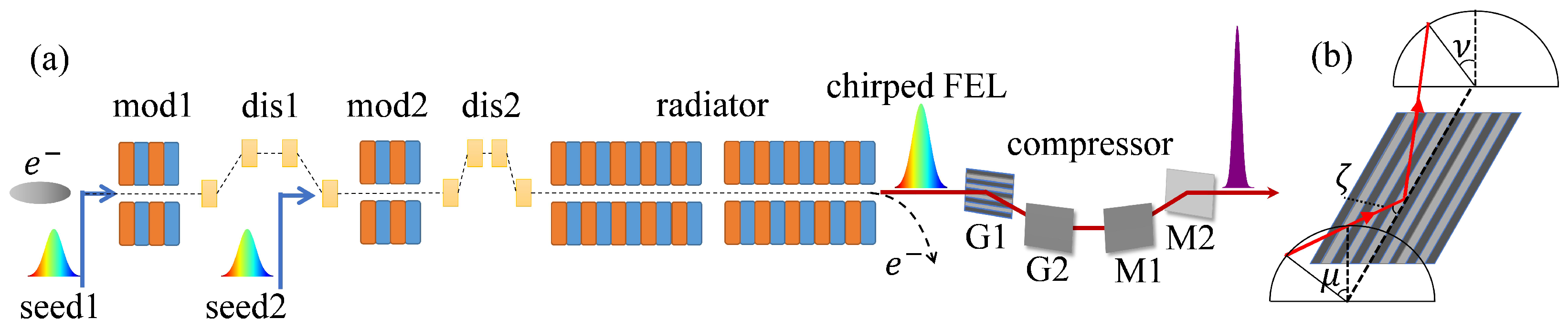
2.1. Chirped-Pulse Amplification in EEHG

The schematic layout of CPA-EEHG is illustrated in Figure 1a. The frequency-chirped seed laser pulses are obtained by stretching the commercial laser pulses with a pair of gratings. These chirped seed laser pulses interact with the same segment of the electron beam in two modulators to generate the desired frequency-chirped energy modulation. With two precisely tuned dispersion sections, the electron beam generates the frequency-chirped bunching at the harmonics of the seed lasers. When passing through the radiator, this bunched electron beam produces the FEL pulse, which inherits the chirped frequency of the seed lasers. Such a chirped pulse can be compressed by a double-grating compressor in the OPM geometry to generate a high-power ultrafast radiation pulse.
The linearly chirped Gaussian pulse can be written mathematically as:
E ( t ) = E 0 exp ( t / τ t ) 2 exp i ( ω 0 t + β t 2 ) .
Hence, the instantaneous frequency is ω i n s = ω 0 + 2 β t , as β determines the chirp rate. To further amplify this chirped pulse, the electron beam should have an energy chirp that matches the resonance condition:
γ ( s ) = n λ u 2 λ s e e d ( s ) ( 1 + a w 2 ) ,
where n is the harmonic number, λ s e e d ( s ) denotes the seed laser wavelength distribution along the longitudinal position s, and λ u and a w denote the undulator period and strength in the radiator, respectively.
As demonstrated in [31], when the seed pulse has considerable frequency dispersion, the FEL pulse bandwidth can be estimated as
( Δ ω ) F E L n 1 α ( Δ ω ) s e e d ,
where ( Δ ω ) s e e d denotes the bandwidth of the seed laser. The factor α is closely linked to the FEL amplification process, which is about 1 / 3 when the FEL reaches saturation. This broadening of the FEL pulse bandwidth results from the competition between the frequency up-conversion process and the nonlinear interactions between the laser pulse and electron beam during the modulation. The above equation points out that the frequency up-conversion at higher harmonics will increase the FEL pulse bandwidth, leading to a smaller FEL pulse duration after compression. Since the harmonic up-conversion number of EEHG is usually larger than that of HGHG, this indicates that, in principle, the compressed FEL pulses in CPA-EEHG will be shorter compared with CPA-HGHG.

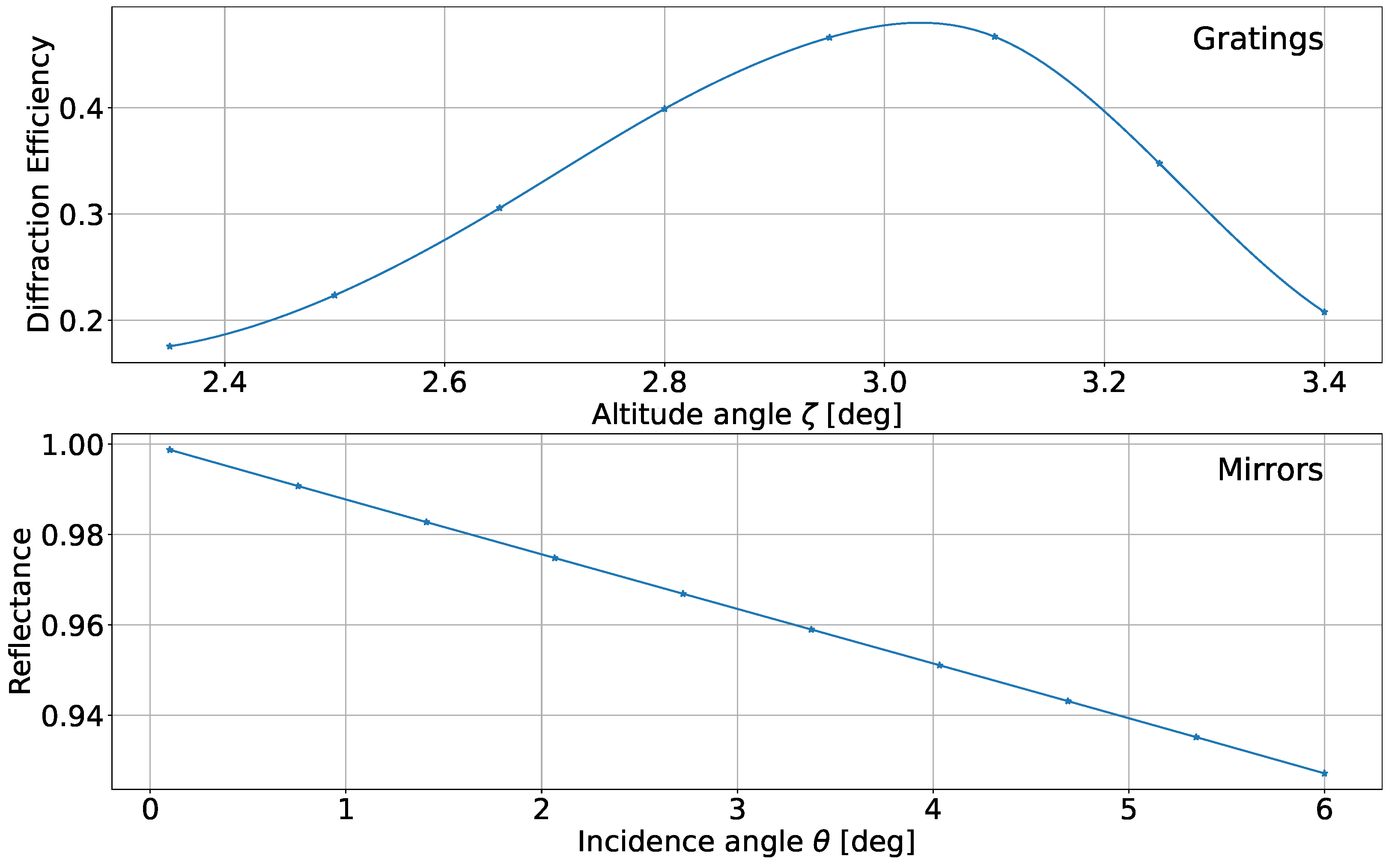
2.2. The Double-Grating Compressor in OPM Geometry

Figure 1a illustrates the fundamental setup of a grazing-incidence double-grating compressor in the OPM geometry, which comprises two identical plane gratings and mirrors. Figure 1b shows the reflection grating of the compressor in the OPM geometry. The grating equation can be written as [35]
sin ζ ( sin μ + sin ν ) = m λ σ ,
where σ denotes the groove density, ζ is the altitude angle of the incidence rays, and μ and ν denote the azimuth angles of the incidence and diffracted rays, respectively. The diffraction efficiency of the grating reaches its maximum when the blaze angle δ equals ( μ + ν ) / 2 . In order to realize the symmetry of the configuration, the azimuth angles μ and ν should satisfy the conditions of μ 2 = ν 1 and ν 2 = μ 1 , where the indices represent the first and second gratings, respectively.
The commercially available reflection gratings in the OPM geometry have a proven peak diffraction efficiency up to 60% for EUV and soft X-rays, which is much higher than the gratings in the classical diffraction mount (CMD) geometry [36]. The total transmission efficiency guarantees the sufficiently high power of the compressed laser pulses.
The definition of the group delay dispersion (GDD) is given by G D D ( ω ) = O P ( ω ) / c ω , where O P ( ω ) denotes the optical path length at frequency ω . As the optical path increases with the wavelength of incident light in most cases, the introduced GDD in the OPM geometry is always negative. In the case of a narrowband pulse with Δ ω / ω < 10 % , specifically in the context of FELs, the GDD is estimated as [35]
G D D = L c ω c 3 2 π σ cos μ 2 ,
where L is the distance between two gratings and ω c = 2 π c / λ denotes the central pulse angular frequency.
After the compressor, the pulse will have its different frequency components separated in the spatial distribution that is perpendicular to the propagation direction. This is called spatial chirp, which may broaden the spot size and degrade the quality of the compressed pulses. For a narrow bandwidth pulse in the FEL, the spatial chirp can be expressed as
S C = L σ cos 2 μ 2 π c ω c 2 Δ ω .
As different frequency components of the pulse are focused in different places, the spatial chirp will lead to an asymmetrical broadening of the spot size. Nonetheless, taking the significant geometric demagnification of the FEL beamline into consideration, the influence of this spatial chirp on the pulses is effectively negligible, as observed at FELs operated in EUV and X-rays [35].

3. Simulation Results

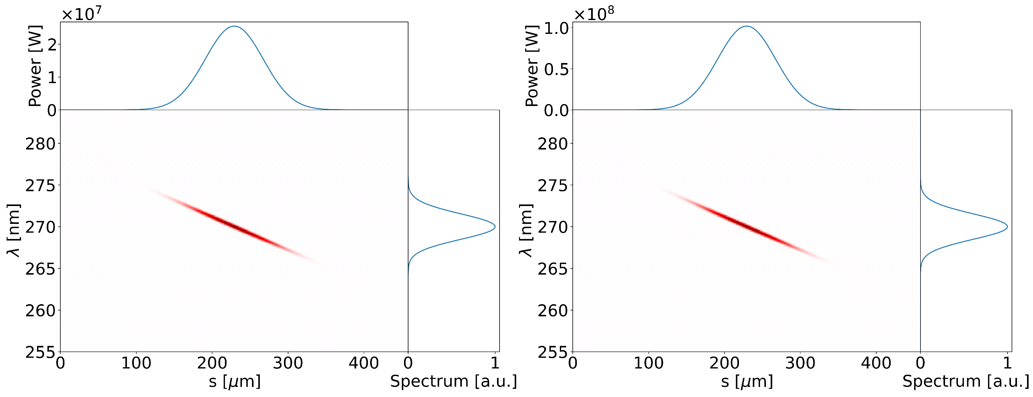
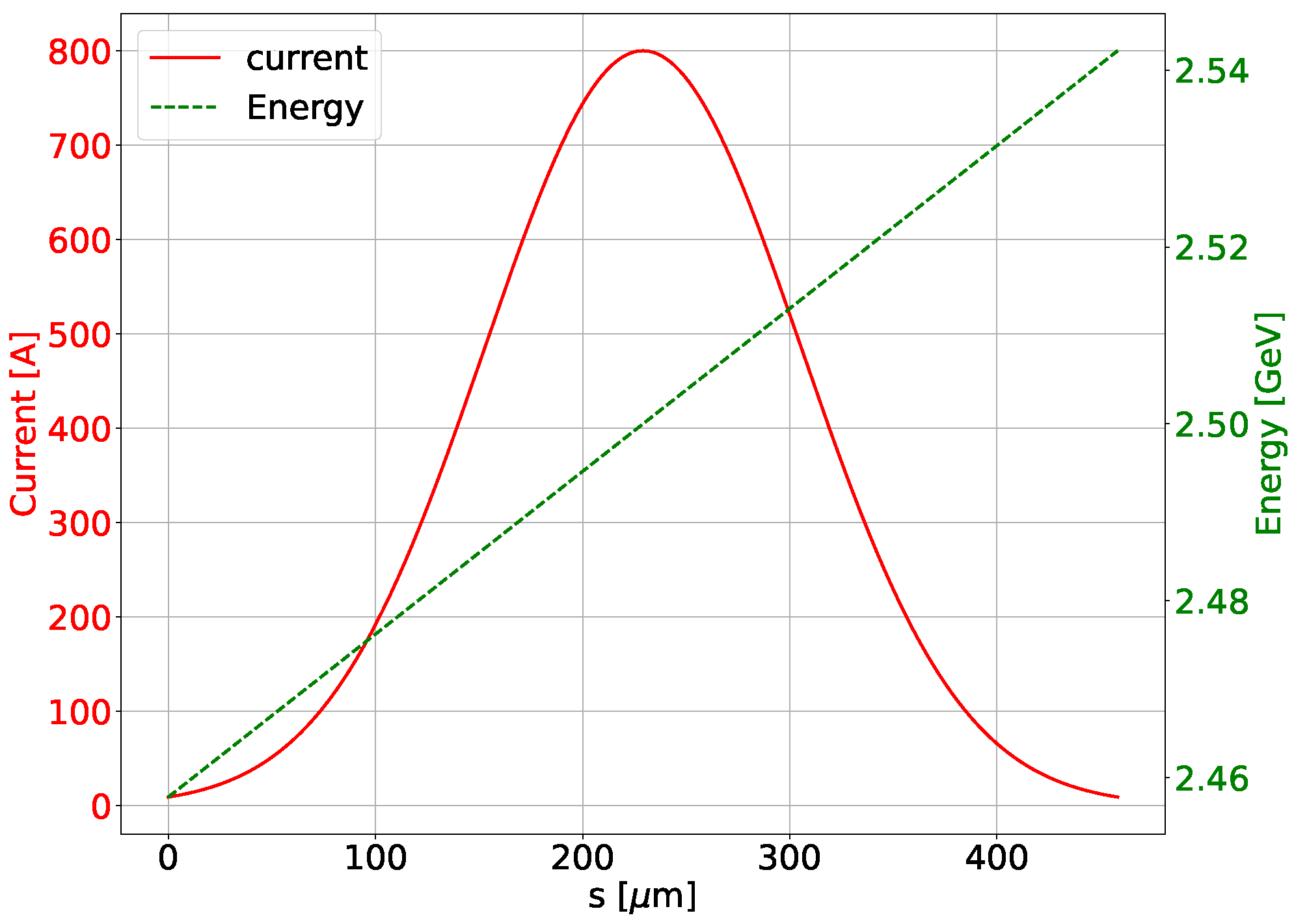
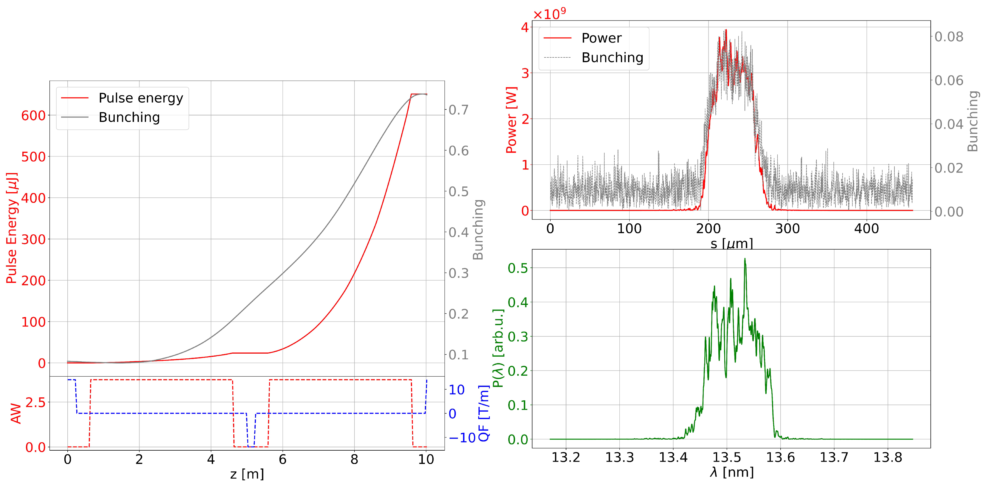
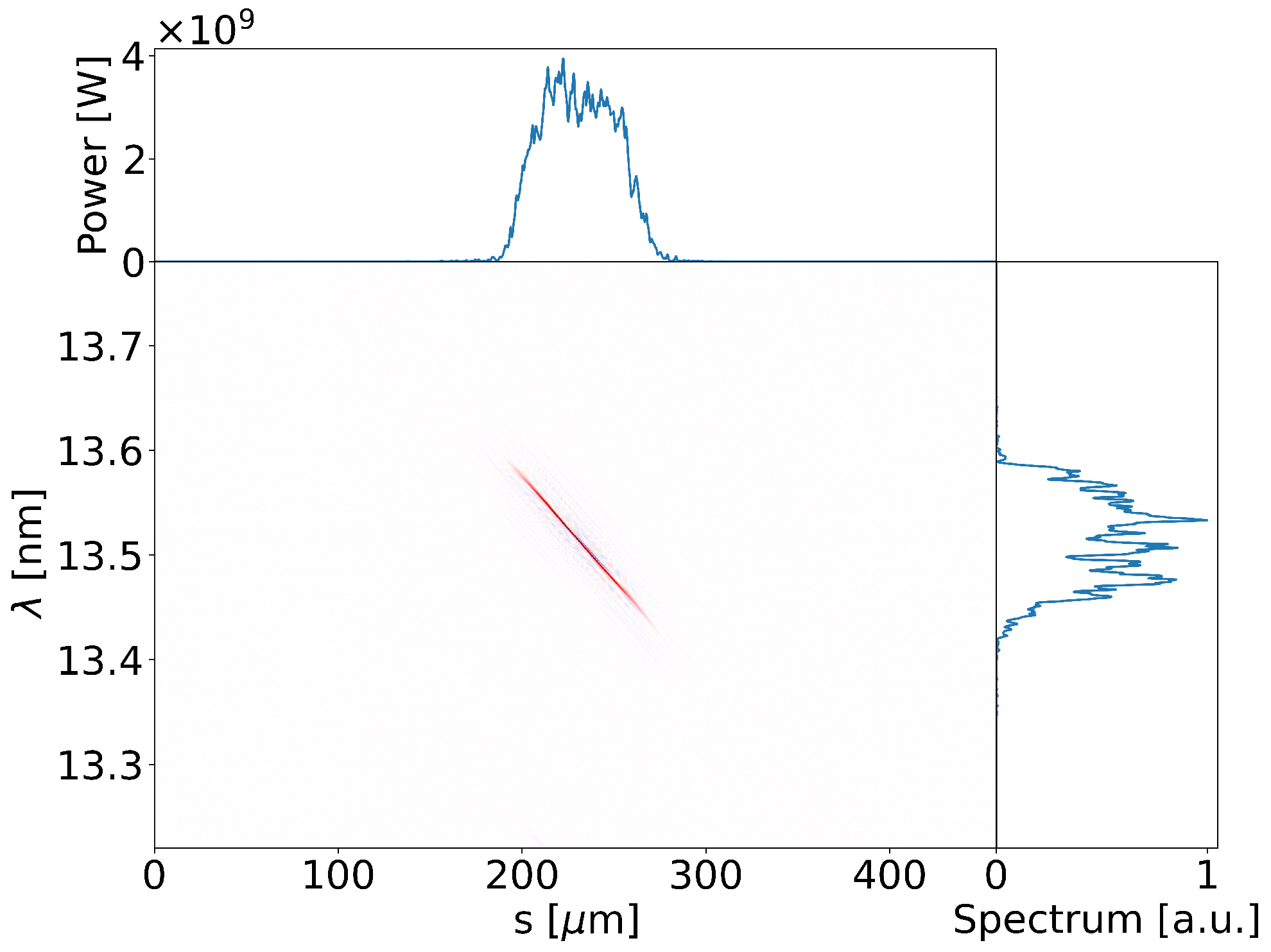
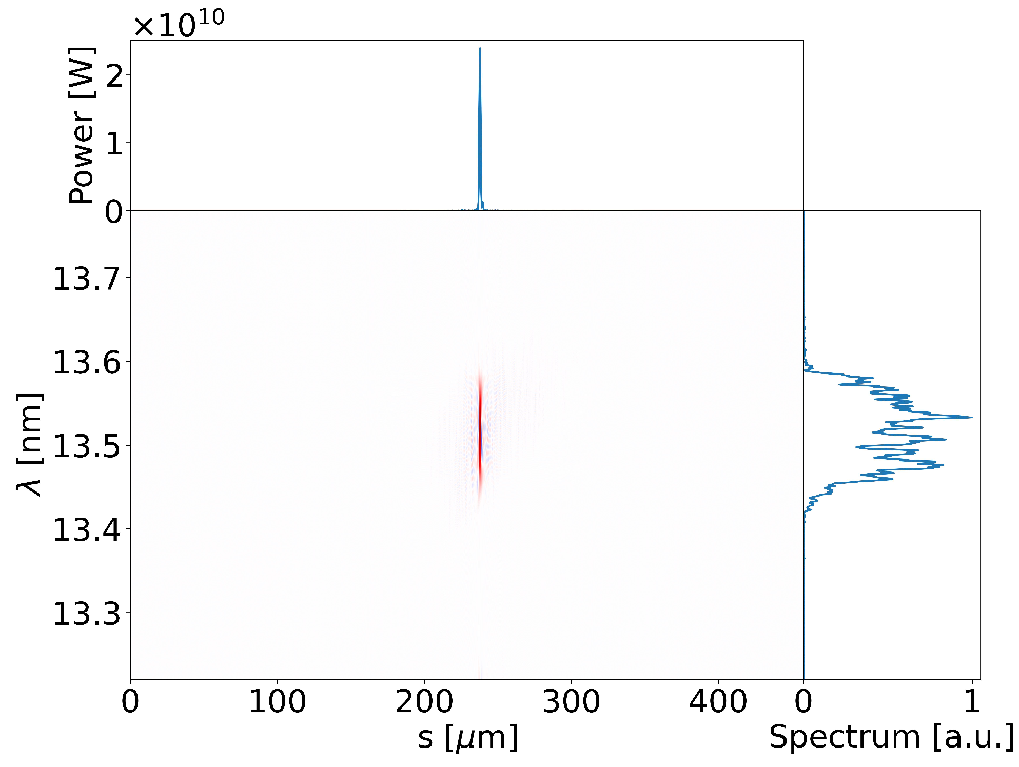
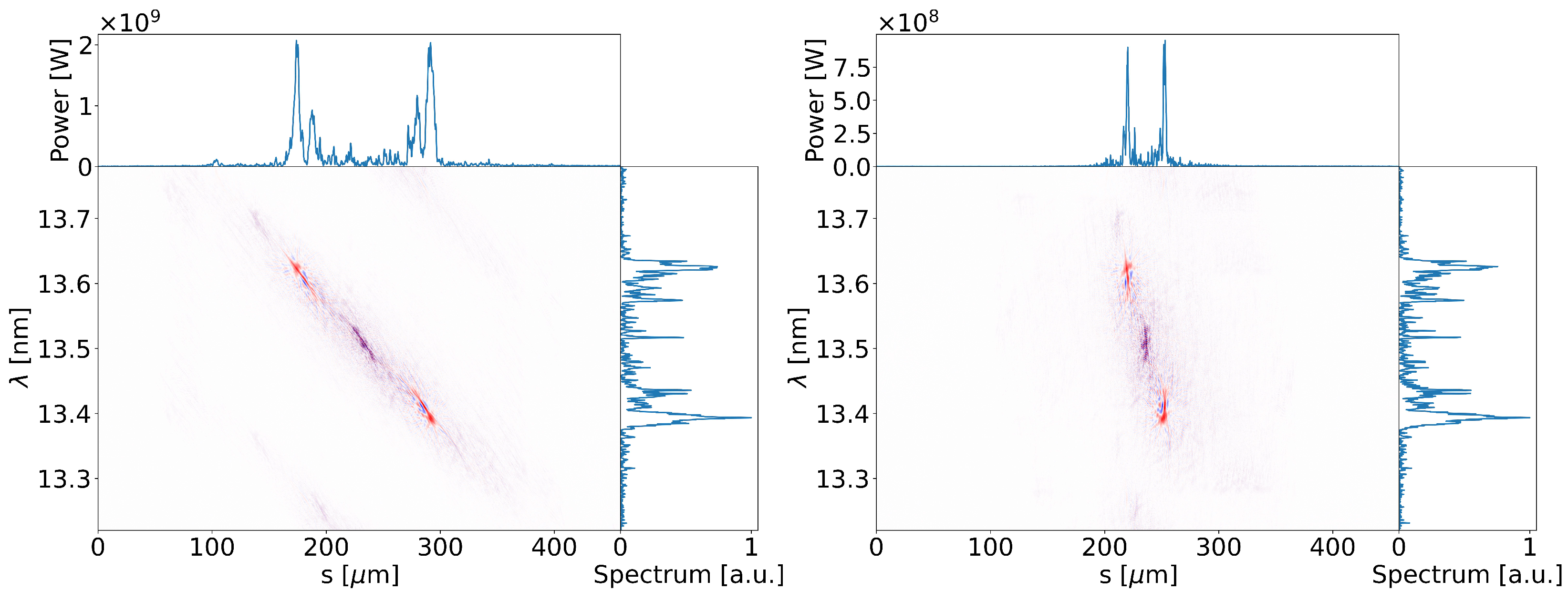
3.1. Simulation Results of CPA-EEHG

In order to investigate the feasibility of CPA-EEHG, a simulation was carried out based on the parameters listed in Table 1. The electron beam energy is 2.5 GeV with a relative slice energy spread of about 10 4 . The electron bunch charge is around 510 pC, and the electron bunch length is about 600 fs. Two laser pulses at 270 nm have been stretched to 300 fs (FWHM) and employed as seed lasers. The peak powers of the stretched seed pulses are about 25 MW and 100 MW, respectively. The Wigner distributions of the seed laser pulses are shown in Figure 2. Two seed lasers have the same linear chirp with a bandwidth ( Δ λ / λ ) of about 1.5%. The modulation section contains two 2 m-long modulators with a period length of 90 mm and two chicanes with total lengths of 10 m and 5 m, respectively. The radiator consists of two 4 m-long variable-gap undulators with a 43 mm period length. The gaps of the undulators are tuned to amplify 13.5 nm (20th harmonic) radiation pulses. The FEL’s performance and radiation pulse propagation were simulated with GENESIS [37] and OCELOT [38], while the design of the compressor was performed with GSolver and XOP [39].
To match the resonance condition in the radiator, a 3.2% energy chirp was imprinted on the electron beam in the simulation. The distributions of the electron beam energy and current are demonstrated in Figure 3. It is noteworthy that there might be a quadratic component in the energy chirp due to the RF curvature in acceleration during the experiment, which will broaden the FEL pulse bandwidth. This effect will slightly degrade the quality of the compressed pulses, leading to the performance degradation of CPA-EEHG. Optimized with the analytical equations in [40], the dispersion strengths R 56 of two chicanes are ∼ 2.20 mm and ∼ 0.12 mm, respectively. After the second dispersion section, the electron beam generates microbunching, which has frequency components at the high harmonics of the seed laser. The relative slice energy spread at the entrance of the radiator is about 3.6 × 10 4 . The utilization of such an electron beam enables the generation and amplification of coherent radiation pulses at 13.5 nm ( n = 20 ) in the radiator.
The simulation results along the radiator and electron bunch are shown in Figure 4. The red and gray lines in the left panel demonstrate the evolution of the FEL pulse energy and electron beam bunching factor, respectively. The pulse energy reaches 651 μ J after two undulators. The optimized 20th harmonic bunching factor (∼8.30%) distribution along the electron bunch at the entrance of the radiator is shown in the right panel. The power profile and the spectrum of the radiation pulse at the end of radiator are also illustrated in Figure 4. The peak power of the output radiation is around 3.94 GW, and the FWHM pulse duration is about 186 fs. The spectral bandwidth of the radiation pulse is approximately 0.81%, which is close to the theoretical expectation of 0.55%.
The Wigner distribution of the radiation pulse after the radiator is shown in Figure 5. Since the gain bandwidth of the modulator (∼4.5%) is several times broader than the bandwidth of the seed laser, all frequency components of the seed pulses effectively contribute to the energy modulation of the electron bunch. Consequently, the linear frequency chirp in the seed laser remains well-preserved in FEL pulses, which enables the compression of the radiation pulses through an optical pulse compressor. As shown in Appendix A, the analysis of the collective effects indicates a slight decrease in the bunching factor (from 8.3 % to 8.1 % ), which is not expected to have a significant impact on the FEL performance.
The generated frequency-chirped FEL pulse propagates through a double-grating compressor, as shown in Figure 1. When the introduced GDD is equal to and opposite the intrinsic GDD of the FEL pulse, the correction of the second-order effects on the phase will lead to a reduction of the pulse duration. The OPM geometry of the grating was adopted for the higher transmission efficiency. The compressor parameters are listed in Table 2. The designed gratings were selected to be commercially available. For the narrow-bandwidth pulses, the GDD introduced by the compressor is about 160 fs2.
The two ruthenium-coated mirrors of the compressor were employed to deflect the FEL beam in the same direction as the input. Figure 6 shows the diffraction efficiency of the gratings and the reflectance of the mirrors at 13.5 nm. Taking the surface roughness and the misalignment of the grating pitch into consideration, the total transmission efficiency of the compressor was up to 15 % at a central wavelength of 13.5 nm.
The compressor also introduces the spatial chirp, which could potentially cause the quality degradation of the compressed FEL pulse. For the compressor designed in the simulation, the spatial chirp calculated in the FWHM bandwidth is about 0.55 mm at the exit of the compressor according to [35]. The transverse spot size of the simulated FEL pulse is 140 μ m with a divergence of around 24 μ rad. The FEL pulse diameter at the compressor entrance is ∼4 mm when the compressor is installed 80 m after the FEL source. Therefore, the introduced spatial chirp is negligible. Moreover, the influence of spatial chirp on the spot size can be mitigated by using an appropriately shaped concave mirror to focus the radiation beam.
Figure 7 shows the Wigner distribution of the FEL pulse after the compressor. Comparing with Figure 5, the pulse length is compressed by roughly 70 times, from 186.43 fs to 2.70 fs, while the peak power correspondingly increases by about 6 times, from 3.94 GW to 23.93 GW. The time–bandwidth product (∼0.486) is only a factor of 1.1 above the transform limit for a Gaussian pulse, which is in satisfactory agreement with the experimental result in [31].
By adjusting the rotations and translations of the two gratings, the azimuth angles μ can be tuned to modify the GDD of the compressor according to Equation (5). An important factor for analyzing the influences of such tunability on the final FEL pulses is the diffraction efficiency of the grating at different azimuth angles. The simulation results indicated that the diffraction efficiency of the grating remains virtually unchanged (varying from 43% to 46%) at the altitude angle of 3 when the azimuth angle is tuned within ± 3 .
The GDD at variable azimuth angles is shown in Figure 8, which provides significant flexibility for the performance of the compressor. When tuning the azimuth angle, the FEL pulses will experience a process from under-compression to over-compression. This leads to the variation of the peak power and pulse duration of the compressed FEL pulses. As can be seen from Figure 8, the pulse duration features a declining trend at the beginning and rising up in later period, while the peak power shows an opposite tendency. The critical point is found at the designed azimuth angle, with the final compressed pulse shown in Figure 7. The spatial chirp when the gratings are rotated is also demonstrated in Figure 8. This introduced spatial chirp is significantly smaller than the spot size of the FEL pulse at the entrance of the compressor and is, therefore, negligible. The peak power can still remains above 20 GW even when the incidence azimuth angle is tuned from ∼26 to 29 .
In comparison to the previous CPA-HGHG method, there are noticeable advantages of the proposed CPA-EEHG scheme. On the one hand, the larger harmonic up-conversion number in CPA-EEHG leads to a shorter wavelength and smaller FEL pulse duration according to Equation (3). On the other hand, the compressor in the OPM geometry with much higher diffraction efficiency guarantees an increase of the peak power by orders of magnitude. It is worth mentioning that extending the wavelength of the output FEL pulses to the X-ray regime is achievable without any compromise in the FEL peak power at CPA-EEHG.

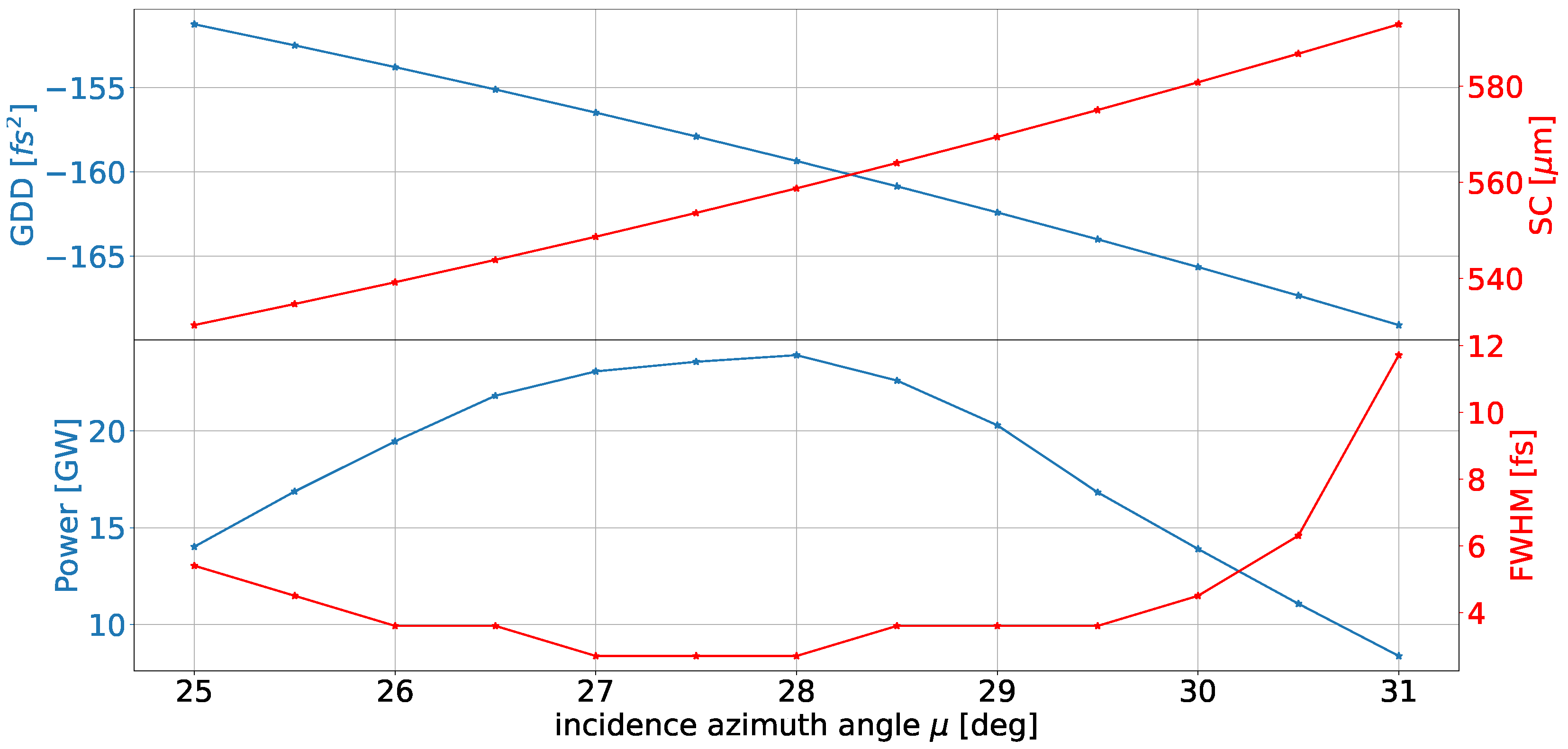
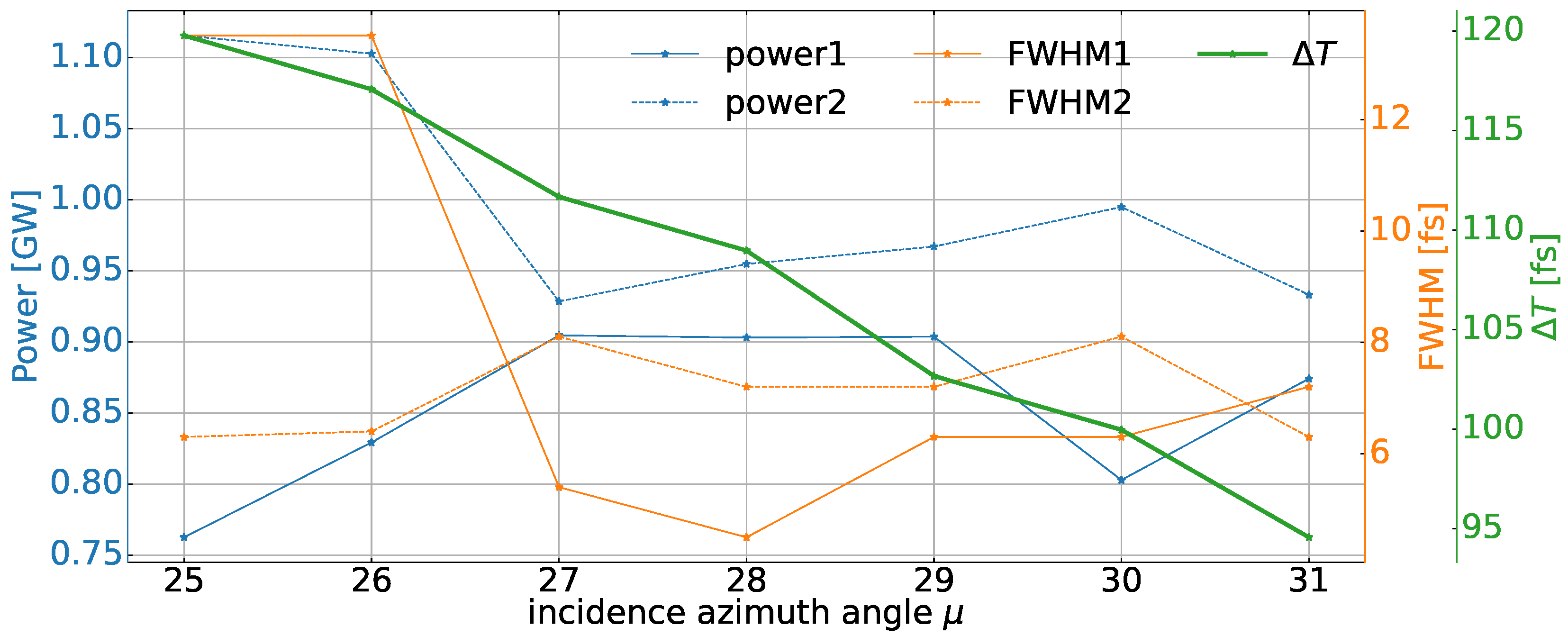
3.2. Simulation Results of a Two-Color Scheme

The generation of two-color FEL pulses with extraordinary brightness presents new prospects for numerous pump-probe experiments in the VUV to hard X-ray spectral regions. Inspired by [30,41], a similar two-color method has been proposed and simulated based on CPA-EEHG.
The amplitude of the bunching factor in EEHG can be found in [40]. At a given harmonic order and the seed lasers, the strengths of two dispersion section dominate the bunching factor, which further influences the FEL radiation proprieties. A relatively modest change in the settings of the dispersion strengths will result in the “pulse splitting” effect [42,43,44], which has essential impacts on the output-pulse profiles. With the increasing of two dispersion strengths, the pulse will split into two well-separated sub-pulses since the electrons at the pulse center are overbunched, while those close to the head and tail are optimally bunched. These two sub-pulses will exhibit distinct carrier wavelengths due to the considerable frequency chirp present in the initial seed pulses.
In the simulation, the dispersion strengths R 56 are increased to ∼ 4.03 mm and ∼ 0.22 mm, while the seed lasers remain unchanged. The Wigner distributions of the FEL pulses before and after the compressor are demonstrated in Figure 9. The pulse durations of the two compressed pulses were effectively reduced from 14.4 fs and 51.3 fs to 4.5 fs and 7.2 fs, respectively. The peak powers can be maintained at approximately 1 GW, which is sufficient for the majority of two-color pump-probe experiments. The generated FEL twin pulses have a relative time delay of about 109 fs and central wavelengths of 13.63 nm and 13.39 nm. Figure 10 shows the variations of the FEL pulse properties when the gratings are rotated. The relative time delay of the compressed FEL twin pulses can be precisely controlled by tuning the azimuth angle, which might be of great benefit to certain two-color pump-probe experiments.

4. Conclusions

Feasibility studies of CPA-EEHG were conducted both analytically and numerically with the achievable parameters of the seed lasers and electron beams at existing FEL facilities. By adopting the proposed CPA-EEHG scheme, coherent high-power ultrafast EUV FEL pulses can be generated directly from the commercial seed lasers. A compressor adopting the OPM geometry was designed at a central wavelength of 13.5 nm. Some practical issues were discussed, including the spatial chirp induced by the compressor and the tunability of the scheme. The generation of two-color FEL pulses based on the CPA-EEHG was also investigated. The simulation results demonstrated the possibility of generating femtosecond two-color pulses with a finely controllable relative time delay. The proposed method for generating ultrafast coherent FEL pulses with high peak power is expected to extend the ultrafast nonlinear spectroscopy technique to the extreme ultraviolet and soft X-ray regime.

Author Contributions

Conceptualization, X.W. and L.Z.; methodology, L.Z. and X.W.; software, L.Z.; validation, L.Z., H.Y. and X.W.; formal analysis, L.Z.; investigation, L.Z.; resources, L.Z.; data curation, L.Z.; writing—original draft preparation, L.Z.; writing—review and editing, L.Z., X.W., Y.L., H.Y. and W.Z.; visualization, L.Z. and Y.L.; supervision, W.Z.; project administration, X.Y.; funding acquisition, X.W., W.Z. and X.Y. All authors have read and agreed to the published version of the manuscript.

Funding

This work is supported by the Shenzhen Science and Technology Program (Grant No. RCBS20210609104332002), the Scientific Instrument Developing Project of Chinese Academy of Sciences (Grant No. GJJSTD20190002), and the National Natural Science Foundation of China (Grant No. 22288201).

Institutional Review Board Statement

Not applicable.

Informed Consent Statement

Not applicable.

Data Availability Statement

The data that support the results of this study are available from the corresponding author upon reasonable request.

Acknowledgments

The authors would like to thank Chao Feng, Zhen Wang, Guorong Wu, Yong Yu, Qinming Li, Jitao Sun, and Xinmeng Li for useful suggestions and comments on the simulations.

Conflicts of Interest

The authors declare that there are no conflict of interest regarding the publication of this article.

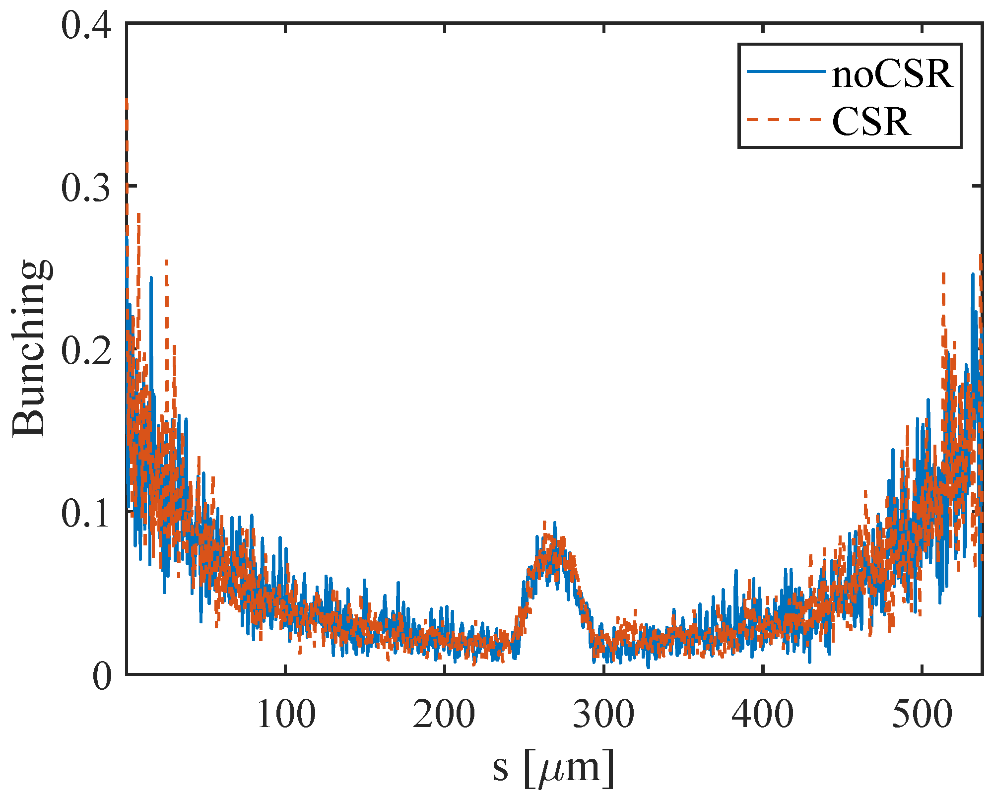
Appendix A. The Influence of Collective Effects

The collective effects can potentially result in a deterioration of the FEL performance in EEHG. In this Appendix, we conducted an investigation into the impact of coherent synchrotron radiation (CSR) through simulations, as well as the effect of incoherent synchrotron radiation (ISR) and intra-beam scattering (IBS) via theoretical calculation:
Coherent synchrotron radiation (CSR):
The strong chicane in the first dispersion section makes the system vulnerable to the CSR effect. It imprints a long-wavelength energy modulation on the electron bunch. Such an energy modulation will interfere with the bunching process, which eventually leads to a decrease of the bunching factor [45]. In order to evaluate this influence on the proposed scheme, the simulation was performed with OCELOT.
Each dipole has a length of 0.3 m. The drift lengths between the first and second dipoles in two chicanes are 4 m and 1.5 m, respectively. This leads to relatively small bend angles in the dipoles, which are about 0.0162 rad for the first chicane and 0.0059 rad for the second chicane. The influence of the CSR on the bunching factor can be found in Figure A1. The electron beam is slightly lengthened after modulation, and the bunching factor remains largely unaffected. This indicates a relatively minor influence of the CSR on the electron beam. However, it should be emphasized that the extent of the CSR’s impact is subject to variation based on the specific configurations of the chicanes.
Incoherent synchrotron radiation (ISR):
Despite the CSR, the ISR effect induced by the strong chicane will also smear the fine structure of the longitudinal phase space. The ISR quantum-diffusion-induced energy spread growth can be written as [46]
( σ Δ E ) I S R = 7 15 m c L r c γ 4 k ω 3 K μ 2 F ( K μ ) 1 / 2 ,
where r c is the classical radius of the electron and k ω and K μ denote the undulator wavenumber and the strength of the undulator, respectively. F ( K μ ) = 1.2 K μ + 1 / ( 1 + 1.33 K μ + 0.4 K μ 2 ) . According to the parameters specified in Table 1, the ISR-induced quantum diffusion effect was calculated to be about 13.2 eV, which is much smaller than the spacing of adjacent energy bands (~ 140 keV) and, therefore, negligible.
Intra-beam scattering (IBS):
The IBS describes multiple Coulomb scatterings in the electron beam, which leads to an increasing electron beam size and energy spread [47]. The IBS-induced energy spread growth can be expressed as [48]
( σ Δ E ) I B S 2 π 3 / 2 ln Λ r c I I A 1 4 π σ x 3 β x γ s 1 / 2 E 0 ,
where I denotes the beam current, I A 17 kA is the Alfven current, σ x and β x denote transverse beam size and transverse β -function, s is the distance along the beamline, and E 0 511 keV is the static electron energy. ln Λ denotes the Coulomb logarithm, which is calculated as
ln Λ = ln 2 6 ϵ N 3 r c σ x 2 I I A 1 / 2 γ 1 / 2 ln 2 ϵ N η σ x ,
where ϵ N denotes the electron beam normalized emittance.
The decreasing bunching factor can be estimated by b h = b h ( 0 ) e l / L [49], where L = 2 σ E 2 / D m 2 B 2 2 . By utilizing the parameters listed in Table 1, the IBS-induced energy spread growth is about 8.6 keV, and the bunching factor decreases from 8.3 % to 8.1 % .

References

  1. Nandi, S.; Olofsson, E.; Bertolino, M.; Carlström, S.; Zapata, F.; Busto, D.; Callegari, C.; Di Fraia, M.; Eng-Johnsson, P.; Feifel, R.; et al. Observation of Rabi dynamics with a short-wavelength free-electron laser. Nature 2022, 608, 488–493. [Google Scholar] [CrossRef] [PubMed]
  2. Takaba, K.; Maki-Yonekura, S.; Inoue, I.; Tono, K.; Hamaguchi, T.; Kawakami, K.; Naitow, H.; Ishikawa, T.; Yabashi, M.; Yonekura, K. Structural resolution of a small organic molecule by serial X-ray free-electron laser and electron crystallography. Nat. Chem. 2023, 15, 491–497. [Google Scholar] [CrossRef] [PubMed]
  3. Liu, X.; Liu, P.; Li, H.; Xu, Z.; Jia, L.; Xia, Y.; Yu, M.; Tang, W.; Zhu, X.; Chen, C.; et al. Excited-state intermediates in a designer protein encoding a phototrigger caught by an X-ray free-electron laser. Nat. Chem. 2022, 14, 1054–1060. [Google Scholar] [CrossRef] [PubMed]
  4. Park, S.H.; Katoch, A.; Chae, K.H.; Gautam, S.; Miedema, P.; Cho, S.W.; Kim, M.; Wang, R.P.; Lazemi, M.; de Groot, F.; et al. Direct and real-time observation of hole transport dynamics in anatase TiO2 using X-ray free-electron laser. Nat. Commun. 2022, 13, 2531. [Google Scholar] [CrossRef] [PubMed]
  5. Aquila, A.; Barty, A.; Bostedt, C.; Boutet, S.; Carini, G.; DePonte, D.; Drell, P.; Doniach, S.; Downing, K.; Earnest, T.; et al. The linac coherent light source single particle imaging road map. Struct. Dyn. 2015, 2, 041701. [Google Scholar] [CrossRef] [PubMed]
  6. Stöhr, J.; Scherz, A. Creation of X-ray transparency of matter by stimulated elastic forward scattering. Phys. Rev. Lett. 2015, 115, 107402. [Google Scholar] [CrossRef]
  7. Weninger, C.; Purvis, M.; Ryan, D.; London, R.A.; Bozek, J.D.; Bostedt, C.; Graf, A.; Brown, G.; Rocca, J.J.; Rohringer, N. Stimulated electronic x-ray Raman scattering. Phys. Rev. Lett. 2013, 111, 233902. [Google Scholar] [CrossRef]
  8. Ding, Y.; Behrens, C.; Coffee, R.; Decker, F.J.; Emma, P.; Field, C.; Helml, W.; Huang, Z.; Krejcik, P.; Krzywinski, J.; et al. Generating femtosecond X-ray pulses using an emittance-spoiling foil in free-electron lasers. Appl. Phys. Lett. 2015, 107, 191104. [Google Scholar] [CrossRef]
  9. Tanaka, T.; Ribič, P.R. Shortening the pulse duration in seeded free-electron lasers by chirped microbunching. Opt. Express 2019, 27, 30875–30892. [Google Scholar] [CrossRef]
  10. Mirian, N.S.; Di Fraia, M.; Spampinati, S.; Sottocorona, F.; Allaria, E.; Badano, L.; Danailov, M.B.; Demidovich, A.; De Ninno, G.; Di Mitri, S.; et al. Generation and Measurement of Intense Few-femtosecond Superradiant Extreme-ultraviolet Free-Electron Laser Pulses. Nat. Photonics 2021, 15, 523–529. [Google Scholar] [CrossRef]
  11. Xiao, Y.; Feng, C.; Liu, B. Generating Isolated Attosecond X-Ray Pulses by Wavefront Control in a Seeded Free-Electron Laser. Ultrafast Sci. 2022, 2022, 9812478. [Google Scholar] [CrossRef]
  12. Fan, W.; Qi, Z.; Feng, C.; Zhao, M. Few-femtosecond X-ray pulse generation and pulse duration control in a seeded free-electron laser. Front. Phys. 2023, 11, 176. [Google Scholar] [CrossRef]
  13. Schneidmiller, E.; Dreimann, M.; Kuhlmann, M.; Rönsch-Schulenburg, J.; Zacharias, H. Generation of Ultrashort Pulses in XUV and X-ray FELs via an Excessive Reverse Undulator Taper. Photonics 2023, 10, 653. [Google Scholar] [CrossRef]
  14. Zholents, A.A. Method of an enhanced self-amplified spontaneous emission for x-ray free electron lasers. Phys. Rev. Spec. Top.-Accel. Beams 2005, 8, 040701. [Google Scholar] [CrossRef]
  15. Prat, E.; Reiche, S. Simple method to generate terawatt-attosecond X-ray free-electron-laser pulses. Phys. Rev. Lett. 2015, 114, 244801. [Google Scholar] [CrossRef] [PubMed]
  16. Guetg, M.W.; Lutman, A.A.; Ding, Y.; Maxwell, T.J.; Decker, F.J.; Bergmann, U.; Huang, Z. Generation of high-power high-intensity short x-ray free-electron-laser pulses. Phys. Rev. Lett. 2018, 120, 014801. [Google Scholar] [CrossRef] [PubMed]
  17. Shim, C.H.; Parc, Y.W.; Kumar, S.; Ko, I.S.; Kim, D.E. Isolated terawatt attosecond hard X-ray pulse generated from single current spike. Sci. Rep. 2018, 8, 1–10. [Google Scholar] [CrossRef]
  18. Duris, J.; Li, S.; Driver, T.; Champenois, E.G.; MacArthur, J.P.; Lutman, A.A.; Zhang, Z.; Rosenberger, P.; Aldrich, J.W.; Coffee, R.; et al. Tunable isolated attosecond X-ray pulses with gigawatt peak power from a free-electron laser. Nat. Photonics 2020, 14, 30–36. [Google Scholar] [CrossRef]
  19. Maine, P.; Strickland, D.; Bado, P.; Pessot, M.; Squier, J.; Mourou, G.; Harter, D. Ultrahigh peak power pulses from solids using chirped pulse amplification. In Proceedings of the International Quantum Electronics Conference, Tokyo, Japan, 18–21 July 1988; Optica Publishing Group: Washington, DC, USA, 1988; Volume QE-24, p. TuD5. [Google Scholar]
  20. Pellegrini, C. High power femtosecond pulses from an X-ray SASE-FEL. Nucl. Instrum. Methods Phys. Res. Sect. A Accel. Spectrometers Detect. Assoc. Equip. 2000, 445, 124–127. [Google Scholar] [CrossRef]
  21. Li, Y.; Lewellen, J.; Huang, Z.; Sajaev, V.; Milton, S.V. Time-resolved phase measurement of a self-amplified free-electron laser. Phys. Rev. Lett. 2002, 89, 234801. [Google Scholar] [CrossRef]
  22. Saldin, E.L.; Schneidmiller, E.A.; Yurkov, M.V. Self-amplified spontaneous emission FEL with energy-chirped electron beam and its application for generation of attosecond x-ray pulses. Phys. Rev. Spec. Top.-Accel. Beams 2006, 9, 050702. [Google Scholar] [CrossRef]
  23. Li, H.; MacArthur, J.; Littleton, S.; Dunne, M.; Huang, Z.; Zhu, D. Femtosecond-Terawatt Hard X-Ray Pulse Generation with Chirped Pulse Amplification on a Free Electron Laser. Phys. Rev. Lett. 2022, 129, 213901. [Google Scholar] [CrossRef]
  24. Yu, L.H.; Babzien, M.; Ben-Zvi, I.; DiMauro, L.; Doyuran, A.; Graves, W.; Johnson, E.; Krinsky, S.; Malone, R.; Pogorelsky, I.; et al. High-gain harmonic-generation free-electron laser. Science 2000, 289, 932–934. [Google Scholar] [CrossRef]
  25. Stupakov, G. Using the beam-echo effect for generation of short-wavelength radiation. Phys. Rev. Lett. 2009, 102, 074801. [Google Scholar] [CrossRef] [PubMed]
  26. Zhao, Z.T.; Wang, D.; Chen, J.H.; Chen, Z.H.; Deng, H.X.; Ding, J.G.; Feng, C.; Gu, Q.; Huang, M.M.; Lan, T.H.; et al. First Lasing of an Echo-Enabled Harmonic Generation Free-Electron Laser. Nat. Photonics 2012, 6, 360–363. [Google Scholar] [CrossRef]
  27. Hemsing, E. Echo-Enabled Harmonic Generation. In Synchrotron Light Sources and Free-Electron Lasers: Accelerator Physics, Instrumentation and Science Applications; Springer International Publishing: Cham, Switzerland, 2020; pp. 225–243. [Google Scholar] [CrossRef]
  28. Yang, X.; Penn, G.; Yu, L.H.; Smaluk, V.; Shaftan, T. Optimization of Echo-Enabled Harmonic Generation toward Coherent EUV and Soft X-ray Free-Electron Laser at NSLS-II. Sci. Rep. 2022, 12, 9437. [Google Scholar] [CrossRef] [PubMed]
  29. Yu, L.; Shaftan, T.; Liu, D.; Tsang, T.; Rose, J.; Wang, X.; Watanabe, T. Chirped pulse amplification experiment at 800-nm. In Proceedings of the 28th International Free Electron Laser Conference (FEL 2006), Berlin, Germany, 27 August–1 September 2006; pp. 194–197. [Google Scholar]
  30. Feng, C.; Shen, L.; Zhang, M.; Wang, D.; Zhao, Z.; Xiang, D. Chirped pulse amplification in a seeded free-electron laser for generating high-power ultrashort radiation. Nucl. Instrum. Methods Phys. Res. Sect. A Accel. Spectrometers Detect. Assoc. Equip. 2013, 712, 113–119. [Google Scholar] [CrossRef]
  31. Gauthier, D.; Allaria, E.; Coreno, M.; Cudin, I.; Dacasa, H.; Danailov, M.B.; Demidovich, A.; Di Mitri, S.; Diviacco, B.; Ferrari, E.; et al. Chirped pulse amplification in an extreme-ultraviolet free-electron laser. Nat. Commun. 2016, 7, 13688. [Google Scholar] [CrossRef]
  32. Schneidmiller, E.; Yurkov, M. Harmonic lasing in x-ray free electron lasers. Phys. Rev. Spec. Top.-Accel. Beams 2012, 15, 080702. [Google Scholar] [CrossRef]
  33. Hemsing, E.; Dunning, M.; Garcia, B.; Hast, C.; Raubenheimer, T.; Stupakov, G.; Xiang, D. Echo-Enabled Harmonics up to the 75th Order from Precisely Tailored Electron Beams. Nat. Photonics 2016, 10, 512–515. [Google Scholar] [CrossRef]
  34. Rebernik Ribič, P.; Abrami, A.; Badano, L.; Bossi, M.; Braun, H.H.; Bruchon, N.; Capotondi, F.; Castronovo, D.; Cautero, M.; Cinquegrana, P.; et al. Coherent Soft X-ray Pulses from an Echo-Enabled Harmonic Generation Free-Electron Laser. Nat. Photonics 2019, 13, 555–561. [Google Scholar] [CrossRef]
  35. Frassetto, F.; Poletto, L. Grating configurations to compress extreme-ultraviolet ultrashort pulses. Appl. Opt. 2015, 54, 7985–7992. [Google Scholar] [CrossRef] [PubMed]
  36. Fabris, N.; Frassetto, F.; Miotti, P.; Samparisi, F.; Spezzani, C.; Zuppella, P.; Poletto, L. Comparison between classical and off-plane diffraction efficiency for the soft x-ray region. In Proceedings of the X-ray Free-Electron Lasers: Advances in Source Development and Instrumentation V. SPIE, Prague, Czech Republic, 3–4 April 2019; Volume 11038, pp. 52–61. [Google Scholar]
  37. Reiche, S. GENESIS 1.3: A fully 3D time-dependent FEL simulation code. Nucl. Instrum. Methods Phys. Res. Sect. A Accel. Spectrometers Detect. Assoc. Equip. 1999, 429, 243–248. [Google Scholar] [CrossRef]
  38. Agapov, I.; Geloni, G.; Tomin, S.; Zagorodnov, I. OCELOT: A software framework for synchrotron light source and FEL studies. Nucl. Instrum. Methods Phys. Res. Sect. A Accel. Spectrometers Detect. Assoc. Equip. 2014, 768, 151–156. [Google Scholar] [CrossRef]
  39. del Rio, M.S.; Dejus, R.J. XOP v2. 4: Recent developments of the x-ray optics software toolkit. Adv. Comput. Methods X-ray Opt. II 2011, 8141, 368–372. [Google Scholar] [CrossRef]
  40. Xiang, D.; Stupakov, G. Echo-enabled harmonic generation free electron laser. Phys. Rev. Spec. Top.-Accel. Beams 2009, 12, 030702. [Google Scholar] [CrossRef]
  41. Mahieu, B.; Allaria, E.; Castronovo, D.; Danailov, M.B.; Demidovich, A.; De Ninno, G.; Di Mitri, S.; Fawley, W.M.; Ferrari, E.; Fröhlich, L.; et al. Two-colour generation in a chirped seeded free-electron laser: A close look. Opt. Express 2013, 21, 22728–22741. [Google Scholar] [CrossRef] [PubMed]
  42. Finetti, P.; Höppner, H.; Allaria, E.; Callegari, C.; Capotondi, F.; Cinquegrana, P.; Coreno, M.; Cucini, R.; Danailov, M.B.; Demidovich, A.; et al. Pulse duration of seeded free-electron lasers. Phys. Rev. X 2017, 7, 021043. [Google Scholar] [CrossRef]
  43. Labat, M.; Joly, N.; Bielawski, S.; Szwaj, C.; Bruni, C.; Couprie, M. Pulse splitting in short wavelength seeded free electron lasers. Phys. Rev. Lett. 2009, 103, 264801. [Google Scholar] [CrossRef]
  44. Gauthier, D.; Ribič, P.R.; De Ninno, G.; Allaria, E.; Cinquegrana, P.; Danailov, M.B.; Demidovich, A.; Ferrari, E.; Giannessi, L.; Mahieu, B.; et al. Spectrotemporal shaping of seeded free-electron laser pulses. Phys. Rev. Lett. 2015, 115, 114801. [Google Scholar] [CrossRef]
  45. Pop, M.; Curbis, F.; Werin, S.; Allaria, E. Mitigation of CSR induced spectral broadening in EEHG FEL. Nucl. Instrum. Methods Phys. Res. Sect. A Accel. Spectrometers Detect. Assoc. Equip. 2023, 1048, 167926. [Google Scholar] [CrossRef]
  46. Feng, C.; Zhao, Z. Hard X-ray Free-Electron Laser Based on Echo-Enabled Staged Harmonic Generation Scheme. Chin. Sci. Bull. 2010, 55, 221–227. [Google Scholar] [CrossRef]
  47. Dattoli, G.; Sabia, E. Bunching coefficients in echo-enabled harmonic generation. Phys. Rev. ST Accel. Beams 2013, 16, 070702. [Google Scholar] [CrossRef]
  48. Zhou, K.; Feng, C.; Wang, D. Feasibility study of generating ultrahigh harmonic radiation with a single stage echo-enabled harmonic generation scheme. Nucl. Instrum. Methods Phys. Res. Sect. A Accel. Spectrometers Detect. Assoc. Equip. 2016, 834, 30–35. [Google Scholar] [CrossRef]
  49. Fan, W.; Feng, C.; Gong, Y.; Sun, H.; Tu, L.; Zhao, M. Hybrid echo-enabled harmonic generation scheme for seeding coherent soft x-ray free-electron lasers. Nucl. Instrum. Methods Phys. Res. Sect. A Accel. Spectrometers Detect. Assoc. Equip. 2022, 1027, 166241. [Google Scholar] [CrossRef]
Figure 1. (a) Schematic layout of the CPA-EEHG. G and M represent the gratings and mirrors in the compressor, respectively. (b) The reflection grating of the compressor in the OPM geometry.
Applsci 13 10292 g001
Figure 2. The Wigner distribution of seed lasers. The projections show the power profiles and spectra of the seed lasers.
Applsci 13 10292 g002
Figure 3. The distribution of the electron beam energy (green) and current (red).
Applsci 13 10292 g003
Figure 4. The simulation results along the radiator (left) and electron bunch (right) of CPA-EEHG.
Applsci 13 10292 g004
Figure 5. The Wigner distribution of the FEL pulse before the compressor.
Applsci 13 10292 g005
Figure 6. The diffraction efficiency of the gratings at different altitude angles (top) and the reflectance of the mirrors at different incidence angles (bottom) at 13.5 nm.
Applsci 13 10292 g006
Figure 7. The Wigner distribution of the FEL pulse after the compressor.
Applsci 13 10292 g007
Figure 8. The variation of the GDD, spatial chirp introduced by the compressor (top), as well as the peak power and pulse duration of the compressed pulses (bottom) when tuning the azimuth angle within ±3 .
Applsci 13 10292 g008
Figure 9. The Wigner distributions of the FEL pulses before (left) and after (right) the compressor.
Applsci 13 10292 g009
Figure 10. The relative time delay (green), the peak power (blue), and the pulse duration (orange) of the compressed pulses when the azimuth angles are tuned within ±3 .
Applsci 13 10292 g010
Figure A1. The influence of the CSR on the bunching factor.
Applsci 13 10292 g0a1
Table 1. Simulation parameters.
SectionParameterValueUnit
Electron beamBeam energy2.5GeV
Emittance0.4/0.4mm · mrad
Peak current800A
Bunch length600fs
Seed laserWavelength270nm
Pulse length300fs
Peak Power∼25/∼100MW
ModulatorPeriod length0.09m
Total length∼2m
DispersionDipole Length0.3m
Total length10/5m
RadiatorPeriod length0.043m
Undulator length4m
Resonant wavelength13.5nm
Table 2. The designed grating parameters.
ParameterValueUnit
Central wavelength13.5nm
Bandwidth0.81%
Groove density3600gr/mm
Blaze angle28
Altitude angle3
G1–G2 distance2.2m
CoatingGold
Disclaimer/Publisher’s Note: The statements, opinions and data contained in all publications are solely those of the individual author(s) and contributor(s) and not of MDPI and/or the editor(s). MDPI and/or the editor(s) disclaim responsibility for any injury to people or property resulting from any ideas, methods, instructions or products referred to in the content.

