Article

Exploratory Thermo-Mechanical Assessment of the Bottom Cap Region of the EU DEMO Water-Cooled Lead Lithium Central Outboard Blanket Segment

by
Gaetano Bongiovì
1,*,
Ilenia Catanzaro
1,
Pietro Alessandro Di Maio
1,
Salvatore Giambrone
1,
Alberto Gioè
1,
Pietro Arena
2 and
Lorenzo Melchiorri
3
1
Dipartimendo di Ingegneria, Università degli Studi di Palermo, 90128 Palermo, Italy
2
Department of Fusion and Nuclear Safety Technology, C. R. Brasimone—ENEA, C.R. Brasimone, 40032 Camugnano, Italy
3
Department of Astronautical, Electrical and Energy Engineering (DIAEE), Nuclear Engineering Section, Sapienza Università di Roma, 00186 Roma, Italy
*
Author to whom correspondence should be addressed.
Appl. Sci. 2023, 13(17), 9812; https://doi.org/10.3390/app13179812
Submission received: 5 August 2023 / Revised: 25 August 2023 / Accepted: 28 August 2023 / Published: 30 August 2023
(This article belongs to the Special Issue Advances in Fusion Engineering and Design)

Abstract

:
The Water-Cooled Lead Lithium (WCLL) Breeding Blanket (BB) is one of the two BB concept candidates to be selected as the driver blanket for the EU DEMO fusion reactor. In this regard, the development of a sound architecture of the WCLL Central Outboard Blanket (COB) Segment, ensuring the fulfilment of the thermal and structural design requirements, is one of the main goals of the EUROfusion consortium. To this purpose, an exploratory research campaign has been launched to preliminarily investigate the thermo-mechanical performances of the Bottom Cap (BC) region of the WCLL COB segment because of its peculiarities making its design different from the other regions. The assessment has been carried out considering the nominal BB operating conditions, the Normal Operation (NO) scenario, as well as a steady-state scenario derived from the in-box LOCA accident, the Over-Pressurization (OP) scenario. Starting from the reference geometric layout of the WCLL COB BC region, a first set of analyses has been launched in order to evaluate its structural performances under a previously calculated thermal field and to select potential geometric improvements. Then, the analysis of a complete BC region was conducted from both the thermal and structural standpoints, evaluating its structural behaviour in compliance with the RCC-MRx code. Finally, after some iterations and geometric updates, a promising geometric layout of the BC region has been obtained even though some criticalities still persist in the internal Stiffening Plates and First Wall. However, the obtained results clearly showed that the proposed layout is worthy to be further assessed to achieve a robust enough configuration. The work has been performed following a theoretical-numerical approach based on the Finite Element Method (FEM) and adopting the quoted Ansys commercial FEM code.

1. Introduction

One of the pivotal components of the EU DEMO fusion reactor is the Breeding Blanket (BB), and its development plays an essential role in the DEMO fusion reactor research activities carried out by the EUROfusion consortium [1,2]. In this context, the Water-Cooled Lead Lithium Breeding Blanket (WCLL BB) is one of the two main candidates as a driver blanket for the EU DEMO fusion reactor.
As already seen in previous works [3,4], the Cap regions of a Blanket Segment are the most critical in terms of loads and requirements they are subjected to, and their design needs dedicated study. In this work, an exploratory thermo-mechanical assessment of the Bottom Cap (BC) region of the EU DEMO WCLL Central Outboard Blanket (COB) segment is reported. In particular, a similar approach to that already followed for the Top Cap (TC) region has been adopted [4].
Starting from the reference geometric layout [5,6], a simplified structural analysis of the single elementary cell housing the Cap, but not including the manifolds region, has been conducted in order to provide a preliminary investigation of its structural performances under an externally calculated thermal field. On the basis of this preliminary assessment, a set of thermo-mechanical analyses has been launched, updating each time the layout of the cell housing the BC, adopting a more detailed geometric layout encompassing the manifolds regions and two cells adjacent to that housing the BC plate. Following a series of progressive modifications, the objective of the activity has been to pave the way for future design works, defining the space of the possible configurations in view of the design requirements. In particular, from the thermal standpoint, the temperature of the structural components, composed of Eurofer, must not exceed the suggested limit value of 550 °C [5]. Instead, the structural performances have been evaluated in light of the RCC-MRx structural design code [7]. The loading conditions taken into account for the evaluation are related to the steady state Normal Operation (NO) and the Over-Pressurization (OP) scenarios, the first taking into account the nominal operative condition, the latter, instead, relating to an off-normal condition resulting from an in-box LOCA event, causing the pressurisation of the whole component, due to a leak of coolant.
To this purpose, a theoretical-numerical approach based on the Finite Element Method (FEM) has been followed, and the quoted Ansys commercial code has been used. The obtained results are herewith presented and critically discussed.

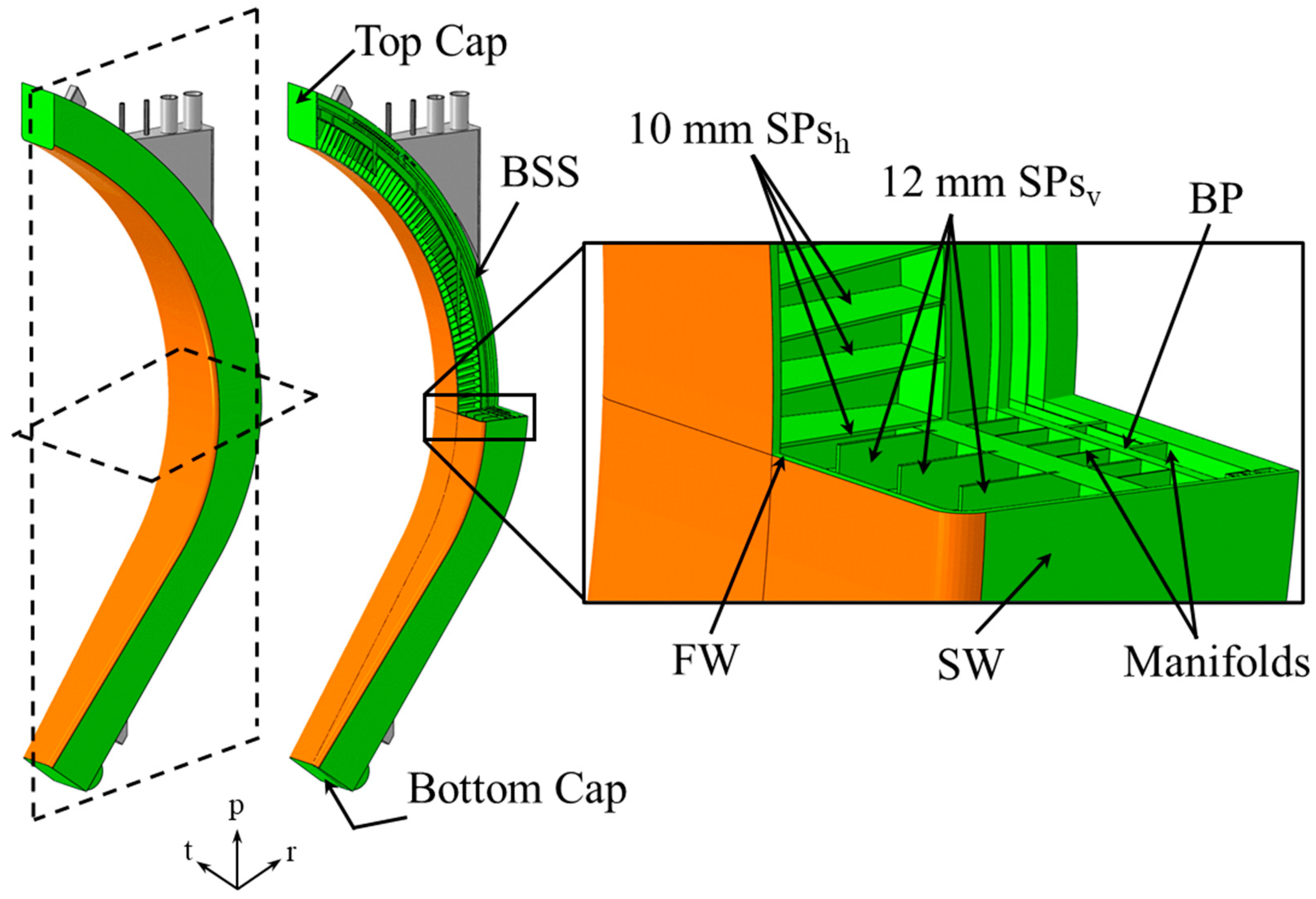
2. The WCLL COB Segment

The EU DEMO WCLL BB, in accordance with the DEMO baseline 2017 [8], is subdivided into 16 identical toroidal sectors of 22.5°, each of them composed of an Outboard and an Inboard region. The Outboard one consists of three segments, Left, Central, and Right (LOB, COB, and ROB, respectively); instead, in the Inboard region, two symmetric segments, Left and Right (LIB and RIB), are foreseen. The Segments are based on the Single Module Segmentation architecture, consisting of a single elementary cell repeated about 100 times for the entire poloidal length of the Segment, which is closed at the extremities by two plates, the Top and Bottom Cap.
The study reported therein is more specifically focused on the Bottom Cap region of the WCLL COB segment, reported in Figure 1. Internally, the COB structure is reinforced by a grid of Stiffening Plates (SPs) located along the poloidal-radial and toroidal-radial planes, respectively named horizontal and vertical SPs (SPh and SPv), with a thickness of 10 and 12 mm, respectively. The external steel structure, named Segment Box (SB), enclosing the SPs grid, is composed of a First Wall (FW), directly placed in front of the plasma and covered with 2 mm of Tungsten (coloured in orange in Figure 1), and laterally closed by Side Walls (SWs). Immediately behind the SPs, the Manifolds region (for water and PbLi) is located, divided by a Back Plate (BP). Finally, at the rear is the Back Supporting Structure (BSS) aimed at connecting the SB with the Vacuum Vessel (VV) by means of the attachment system (in grey in Figure 1). The liquid metal eutectic alloy (acting as breeder, neutron multiplies and tritium carrier), the Lithium-Lead, flows across the SPs in that region called Breeder Zone (BZ), guided in its poloidal path to a series of Baffle Plates. The BZ is actively cooled by subcooled pressurised water (15.5 MPa and 285/328 °C of inlet/outlet temperature) flowing inside the bundle of Double Walled Tubes (DWTs), whose geometric layout varies along the poloidal length of the Segment due to the different thermal loads each region is subjected to [9]. Instead, square cooling channels are located in the FW-SWs region, crossed by water in the same condition aforementioned, devoted to cooling that region. As for the DWTs, the number of cooling channels per elementary cell depends on its poloidal location within the segment. An overview of the cooling channels and DWTs layout for each poloidal region of the COB Segment is reported in [9]. As to the BC region, the reference geometric layout foresaw a Cap plate of 25 mm of thickness and any dedicated cooling system is foreseen.

3. Structural Assessment of the Reference WCLL COB Segment BC Region

The first part of the study concerns the structural study of the reference BC region in order to preliminarily assess its behaviour and to investigate possible improvements to be adopted in a subsequent and more complete analysis. Therefore, on the basis of the layout already considered for the thermal analysis reported in [6], a mechanical FEM model has been set up.

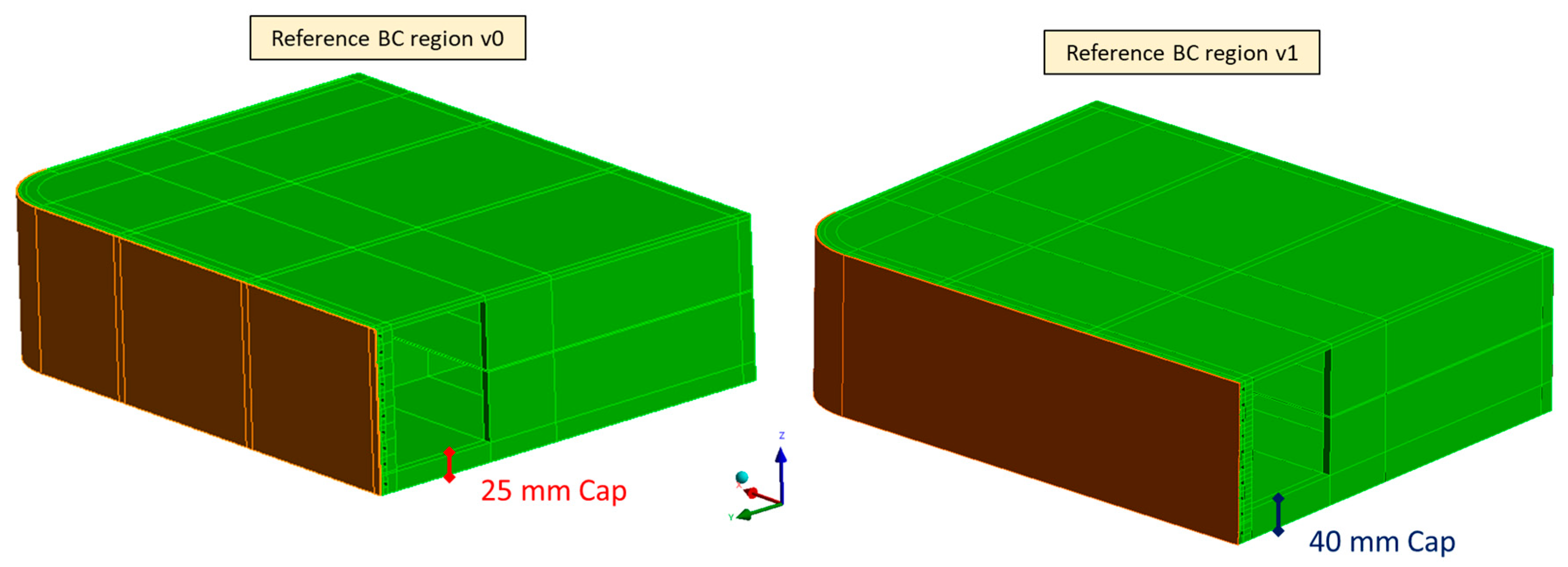
3.1. Reference BC Region v0

In this paragraph, the structural analysis and the results evaluation of the reference geometric layout (v0) of the BC region of the DEMO WCLL COB segment are reported.

3.1.1. The FEM Model

The reference geometric layout of the BC region of the DEMO WCLL COB segment [5,6] has been considered (Figure 2). In particular, only the elementary cell housing the BC plate has been modelled in this phase without including in the model the manifolds region, the BP and the BSS. Moreover, it is important to notice that this elementary cell, housing a BC plate 25 mm thick, has a different poloidal size with respect to the others. Hence, the thermal analysis results reported in [6] show that ten cooling channels are necessary to cool the FW-SWs region, differently than the other elementary cells of the corresponding poloidal region of the COB Segment, equipped with six cooling channels [9]. Moreover, the so-called “v06b” DWT geometric layout has been slightly modified because of the different sizes of this elementary cell.
A realistic 3D FEM model has been set up in order to investigate the structural behaviour of the BC region. DWTs, Breeder and cooling water, have not been directly modelled, but their effects have been properly considered by means of relevant loads and boundary conditions. A mesh composed of ~2 M nodes connected in ~550 k tetrahedral and hexahedral quadratic elements has been set up. Temperature-dependent material properties have been considered, drawn from [10,11]. The following set of loads and boundary conditions has been considered and applied to carry out the structural analysis of the BC region under the NO and OP steady-state loading scenarios [12]:
  • Nonuniform thermal deformation field: The 3D thermal field calculated in [6] has been imported and mapped to the structure, as reported in Figure 3, originating the corresponding deformation field by means of the temperature-dependent coefficient of thermal expansions.
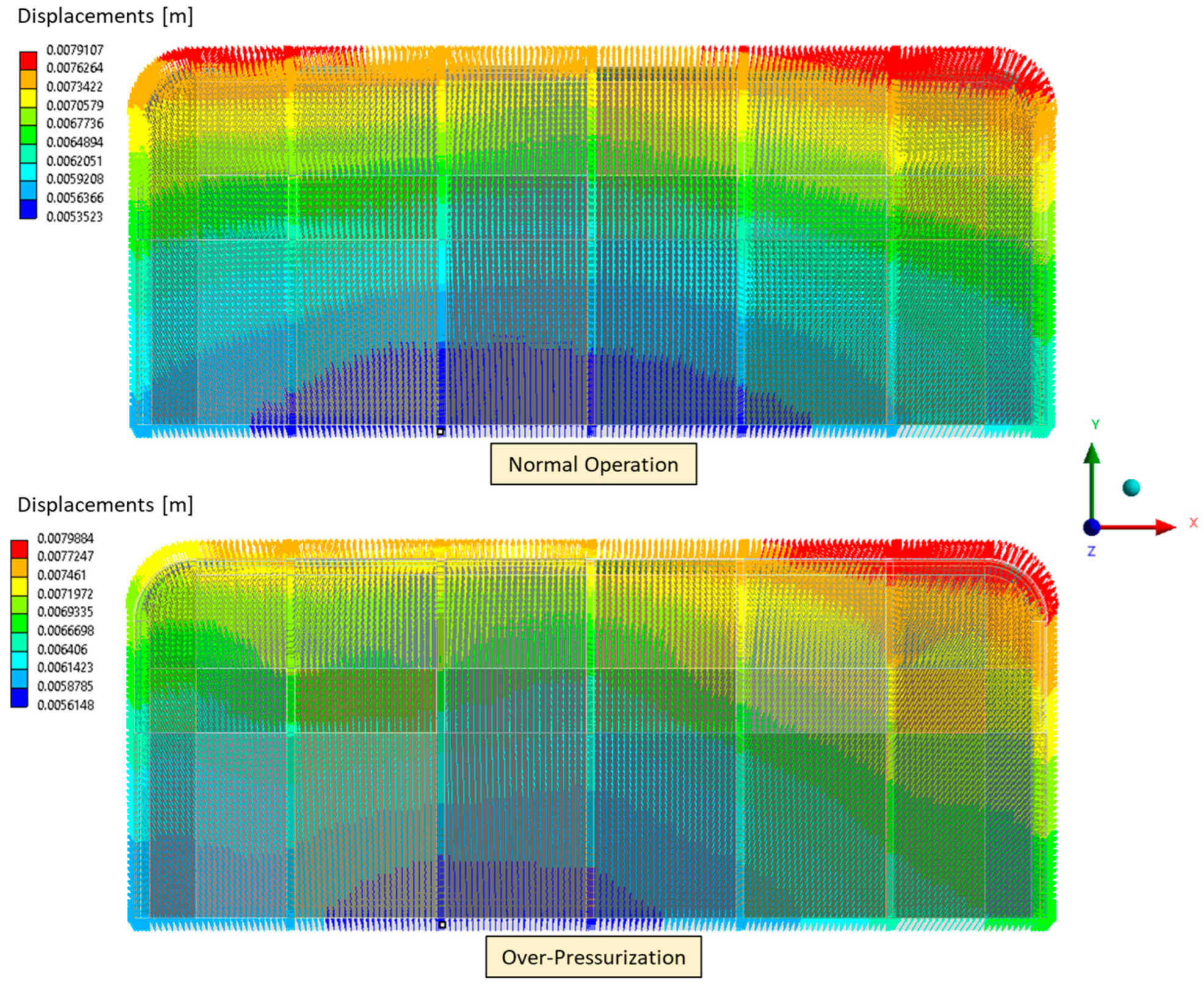
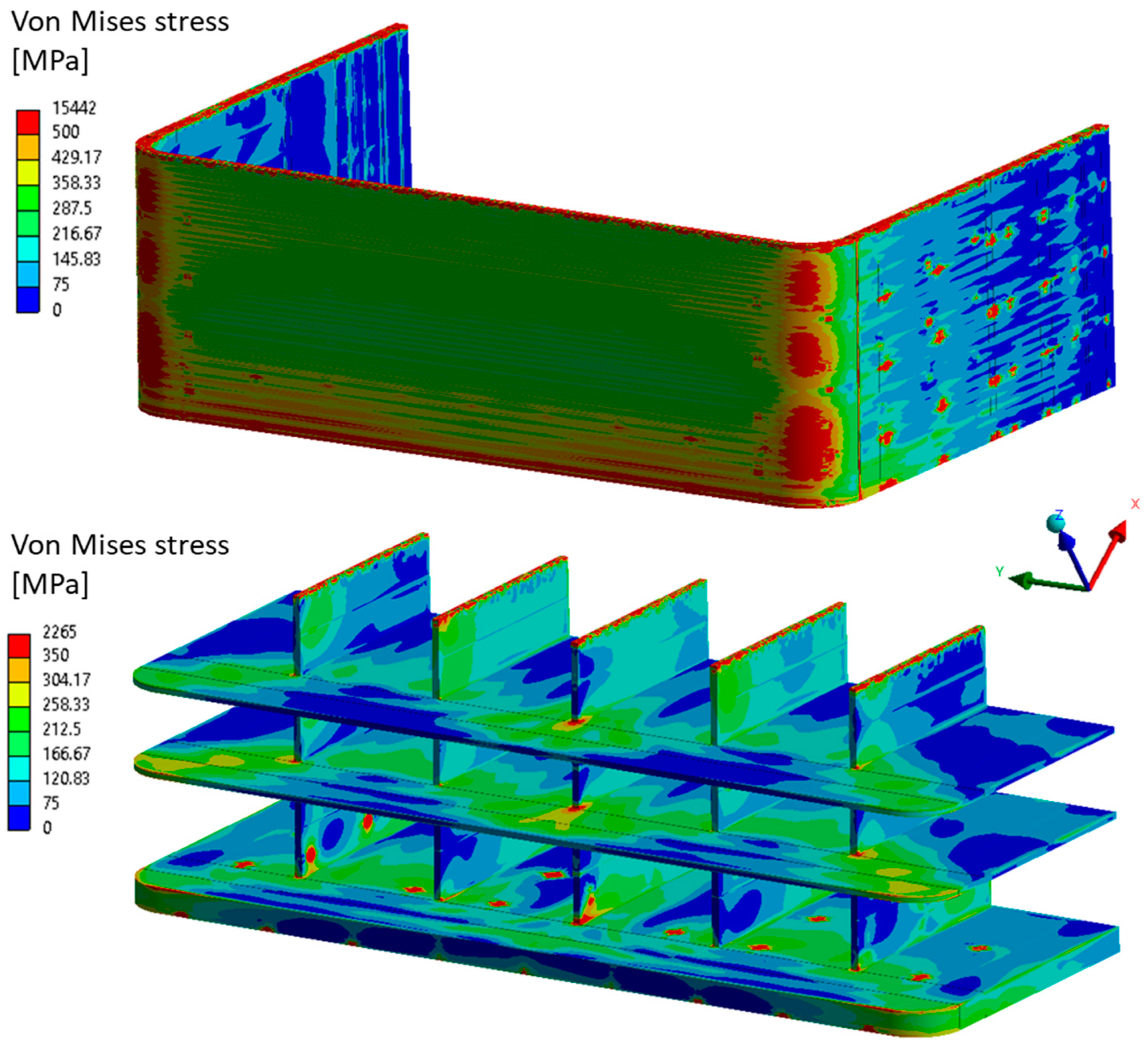
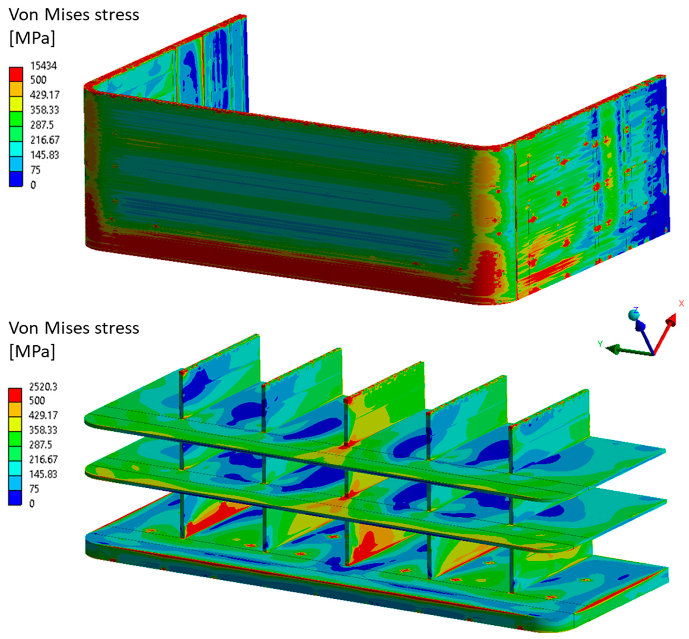
  • Mechanical restraints: With the aim of realistic simulating the presence of the entire COB segment acting on the considered BC region, the displacements field, obtained in [9], has been mapped and applied on the upper surface of the structure, as already achieved in previous analyses [4]. In particular, the corresponding displacement field has been exported from the whole COB Segment analysis and applied in accordance with the considered loading scenario. In Figure 4, the mapped displacement field on the upper surface in NO and OP loading scenarios is reported. For the sake of brevity, the deformed vs. undeformed shapes of the entire COB Segment have not been reported, but they can be easily found by looking at Figure 13 of the reference document [9].
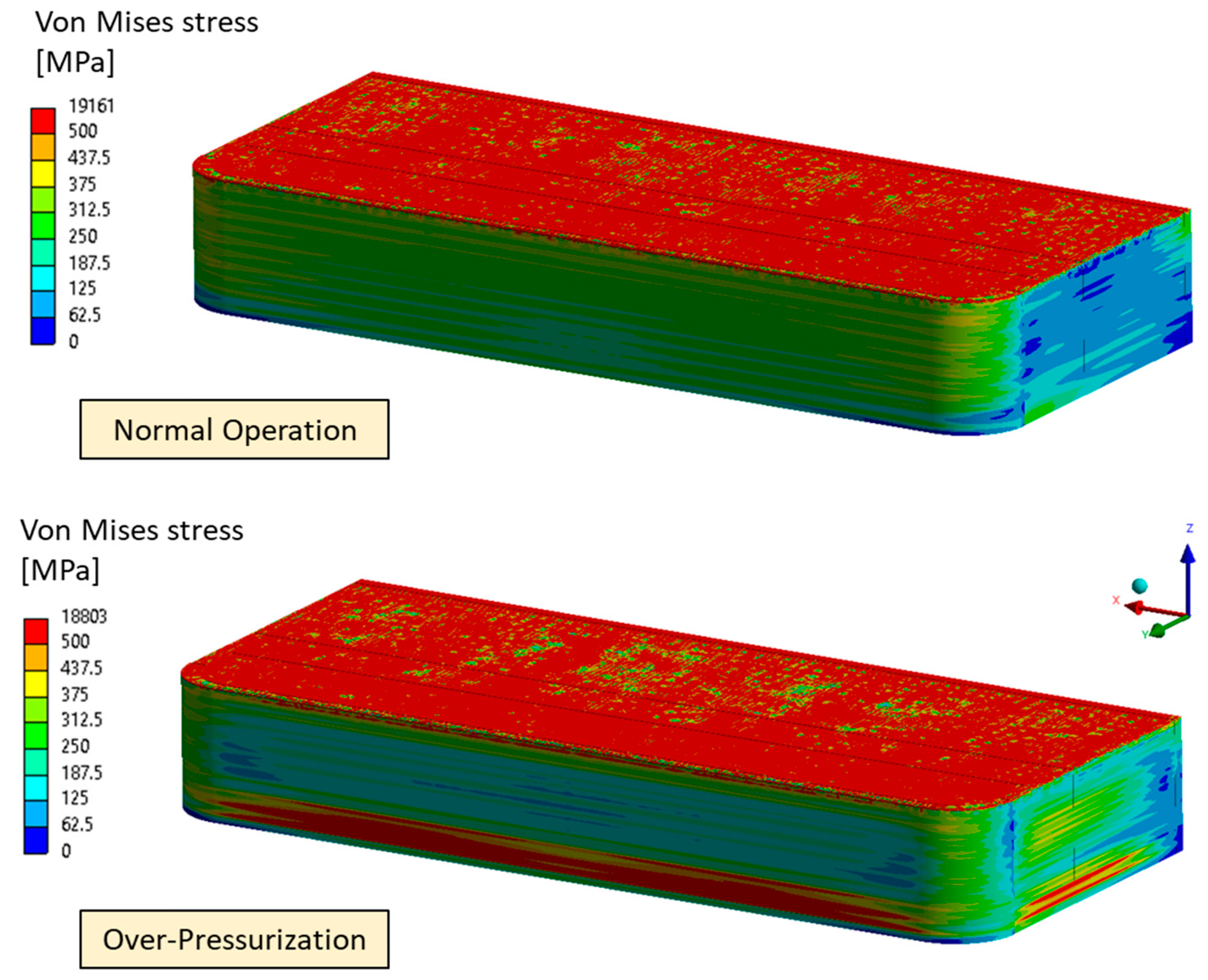
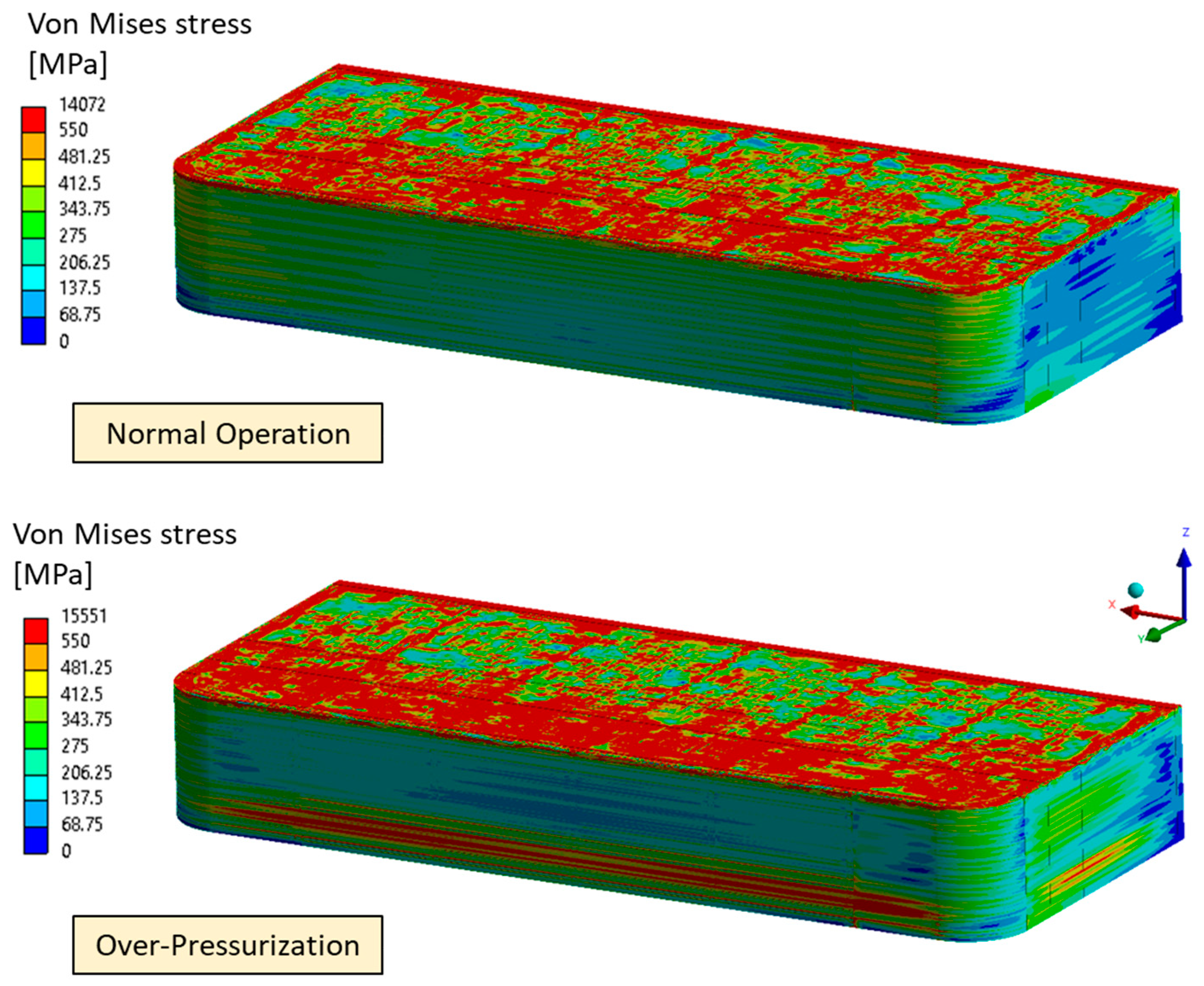
  • Pressure: The design pressures, calculated as the nominal pressure multiplied by a safety factor equal to 1.15, have been applied to the Breeder-wetted and water-wetted surfaces. In particular, a pressure of 17.825 MPa has been considered for the coolant; instead, a pressure of 0.575 MPa for the PbLi has been assumed. During the NO loading scenario, the coolant design pressure has been imposed on the water-wetted surfaces (i.e., the FW-SWs cooling channels), whereas the breeder design pressure has been set to the internal BZ surfaces. As well as the OP scenario, representing an over-pressurisation condition subsequent to an in-box LOCA event, the coolant design pressure has been assumed both for the water-wetted and the breeder-wetted surfaces.
  • Gravity: The gravity load has been applied to the entire structure.
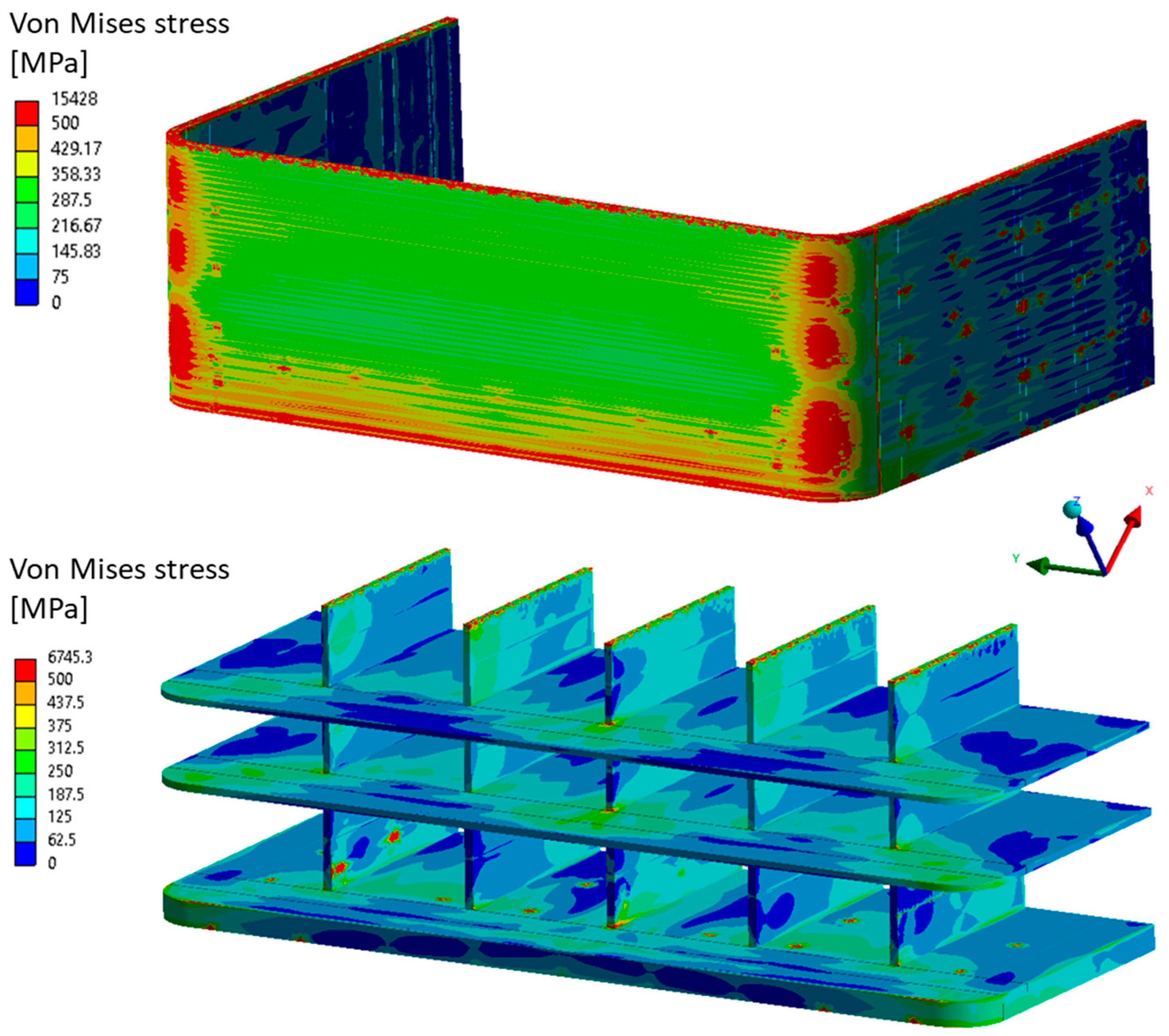
3.1.2. Results

Results in terms of Von Mises Stress fields are reported in Figure 5 for both the selected steady-state loading scenarios. It is important to notice that the upper surface of the elementary cell shows high stress values due to the applied displacement field.
A stress linearisation procedure has been performed along some paths individuated within the model in correspondence with the most stressed region. No paths have been considered within the Baffle Plates as they have any structural role. In particular, six paths have been selected within the vertical SPs and four along the Cap, depicted in Figure 6 and Figure 7 within the FW, as reported in Figure 7, where different sets of paths (AB, CD and EF) are coloured differently.
Then, the fulfilment of the RCC-MRx structural design criteria has been checked. In particular, the NO loading scenario, representing the normal operating conditions, falls under the service Level A, whereas the OP scenario, deriving from an off-normal event, is classified as Level D. Four criteria have been taken into account: Immediate Excessive Deformation (IED, Pm/Sm), Immediate Plastic Instability (IPI, (Pm + Pb)/(Keff ∙ Sm)), Immediate Plastic Flow Localisation (IPFL, (Pm + Qm)/Sem) and Immediate Fracture due to exhaustion of ductility (IF, (Pm + Pb + Q + F)/Set). The first two criteria only consider the primary stresses; instead, the others also take into account secondary stresses occurring along the analysed path. For each criterion, the stress limit values have been calculated for the service level to which each loading scenario analysed relates, in accordance with the structural material and the average path temperature.
The results of the verification of the RCC-MRx design criteria are reported in terms of the ratio between the obtained equivalent stresses along the paths and the corresponding stress limit values for each criterion. Ratios values exceeding unity indicate that the respective criterion is not fulfilled and are highlighted in red; instead, values greater than 0.8 are coloured orange, thereby indicating regions in which the criterion is verified with a small margin, so remaining potentially critical. Results show that all the Level A criteria are fulfilled along all the selected paths, whereas some issues and critical regions are observed along different paths for the Level D criteria. In particular, all the paths within the vertical SPs do not fulfil or reach high values of the IED and IPI criteria, whereas all the paths selected along the Cap thickness reach critical values of the IPI criterion (Table 1).
Therefore, since most of the failures are due to primary stress, the obtained results suggested making the Cap thicker. Hence, as the first improvement, a 40 mm Cap thickness has been considered for the follow-up of the work, as already has been achieved for the TC region [4]. In addition, the possible impact of this modification on the structural response of the FW shall be carefully checked.

3.2. Reference BC Region v1

On the basis of the obtained results of the reference BC region v0 structural analysis, in this paragraph, the structural analysis of the v1 geometric layout is reported, and the obtained results are critically discussed.

3.2.1. The FEM Model
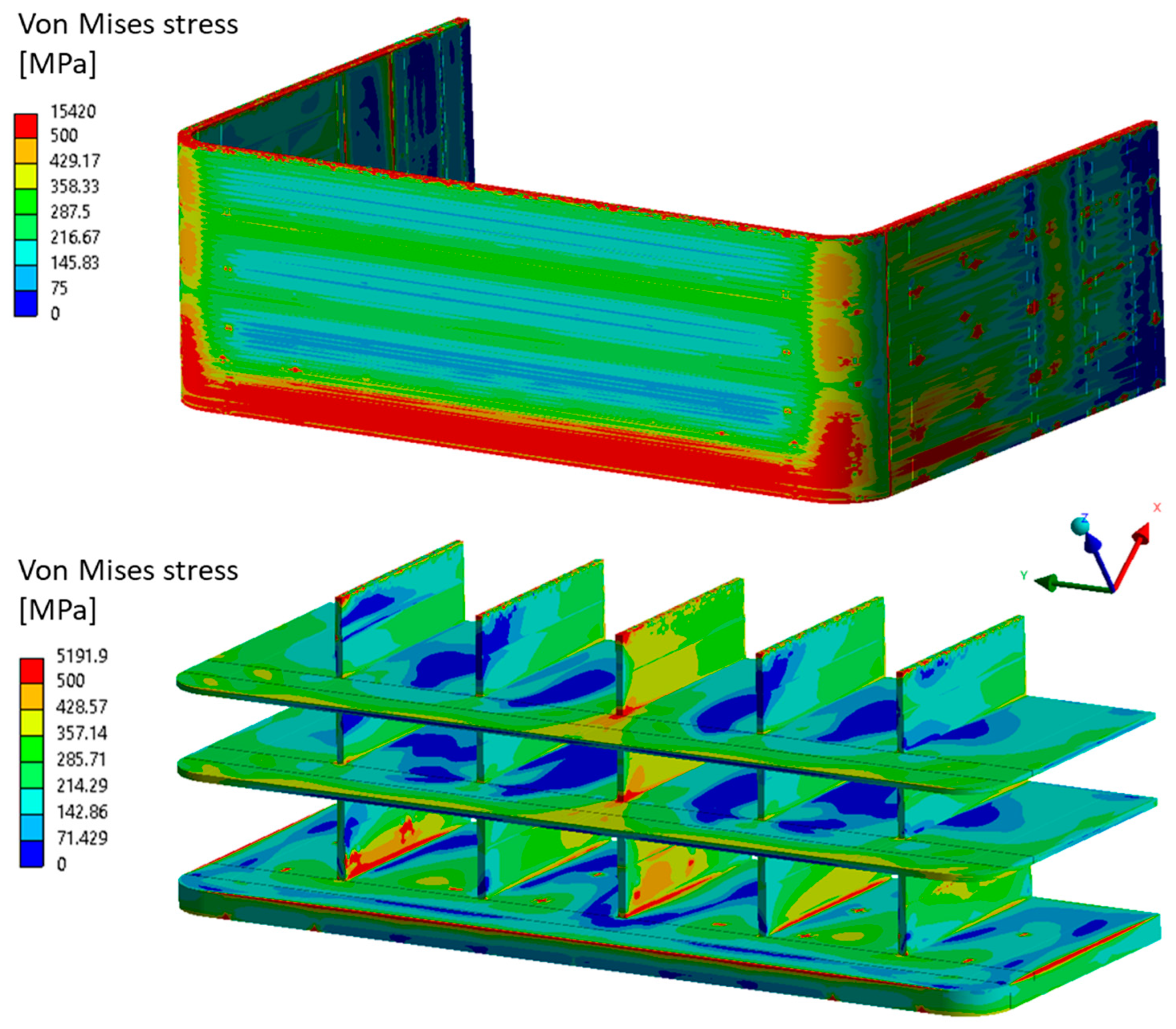
With the aim of investigating the effect of a thicker BC plate on the structural response con the BC region, the reference v0 model has been properly modified by only increasing the Cap thickness, as reported in Figure 8. Therefore, a mesh with the same characteristics as the previous, composed of ~1.3 M nodes connected in ~320 k tetrahedral and hexahedral quadratic elements, has been set up.
The same loads and boundary conditions already seen in Section 3.1.1 have been implemented in the up-to-date model to reproduce both the NO and OP steady-state loading scenarios. It is important to notice that, with regard to the thermal field, it has been mapped on the new model components, as well as on the thicker Cap, from the Reference v0 layout thermal analysis. Therefore, the thermal behaviour is to be considered as an extrapolated one.

3.2.2. Results

Another set of analyses have been launched in order to evaluate the structural behaviour of the up-to-date version of the Reference BC region, with an increased BC thickness equal to 40 mm. In Figure 9, the equivalent Von Mises stress field arose within the structure in NO and OP loading scenarios.
Then, a stress linearisation procedure has been conducted along the same paths already considered for the BC region v0, and the fulfilment of the RCC-MRx design criteria has been checked. As to the NO loading scenario, the results are not reported for the sake of brevity, but similar values to those obtained for the previous configuration have been found. Looking at the OP loading scenario, the results of the RCC-MRx design criteria verification are reported in Table 2. As it can be observed, globally, the criteria are fulfilled, and some critical values are reached; compared with the results of the reference BC region v0 analysis, some criticalities have been mitigated.
Finally, results allow the conclusion that the first adopted improvement provided some enhancements in the structural performances of the considered BC region and, in particular, the Bottom Cap plate performances undergo an evident improvement. Some issues still remain within the vertical SPs and in the lowest region of the Cap, near the cooling channel. In any case, comprehensive analysis of the BC complete region, and the manifold region, is necessary to understand their contribution to its behaviour. Moreover, it is also important to take into account some additional elementary cells, firstly to be able to study in detail the horizontal SPh and, secondly, to ensure that the elementary cell housing the BC plate is far enough from the boundary conditions application and its structural response is not affected. Finally, to investigate in depth the thermo-mechanical behaviour of the BC region, a dedicated thermal analysis is necessary.

4. Thermal and Structural Analysis and Design Improvements of the BC Region

In this second part of the activity, the complete BC region, comprehensive of the manifolds region previously not considered and also of two more elementary cells immediately above, has been analysed both from the thermal and mechanical standpoints. In this section, the complete thermo-mechanical analysis of this configuration and the following updates are reported, and the results are critically discussed.

4.1. The First Update (v1) of the BC Region Design

With the aim of in-depth studying the thermo-mechanical behaviour of the BC region of the WCLL COB segment, the elementary cell housing the BC plate and two additional elementary cells located immediately above have been considered. In particular, the model has been obtained by cutting with a plane passing through the midplane of the considered SPh from the entire model of the COB segment.

4.1.1. The FEM Model

A 3D FEM model of the BC region, obtained by cutting the COB reference design mode, has been set up. The above-considered improvement has been taken into account by increasing the Cap plate thickness from 25 mm (that is the reference value to 40 mm. Then, the elementary cells have been equipped with the proper cooling systems. With regards to the DWTs, the “v06b” layout, consisting of 22 tubes, has been implemented in each cell. Instead, as to the cooling channels within the FW-SWs region, ten channels have been considered for the last cell, containing the BC plate, whereas six channels have been considered for the remaining two cells, as given in the reference layout [9], as reported in Figure 10.
A spatial discretisation grid composed of ~3.8 M nodes connected in ~1.8 M tetrahedral and hexahedral elements, reproducing the BC region structure, DWTs, PbLi, DWTs’ and cooling channels’ water, has been set up. Temperature-dependent material properties have been considered, drawn from [10,11,13].
In order to assess the thermal performances of the BC region under the WCLL BB operational steady state scenario, the following set of loads and boundary conditions [12] has been considered:
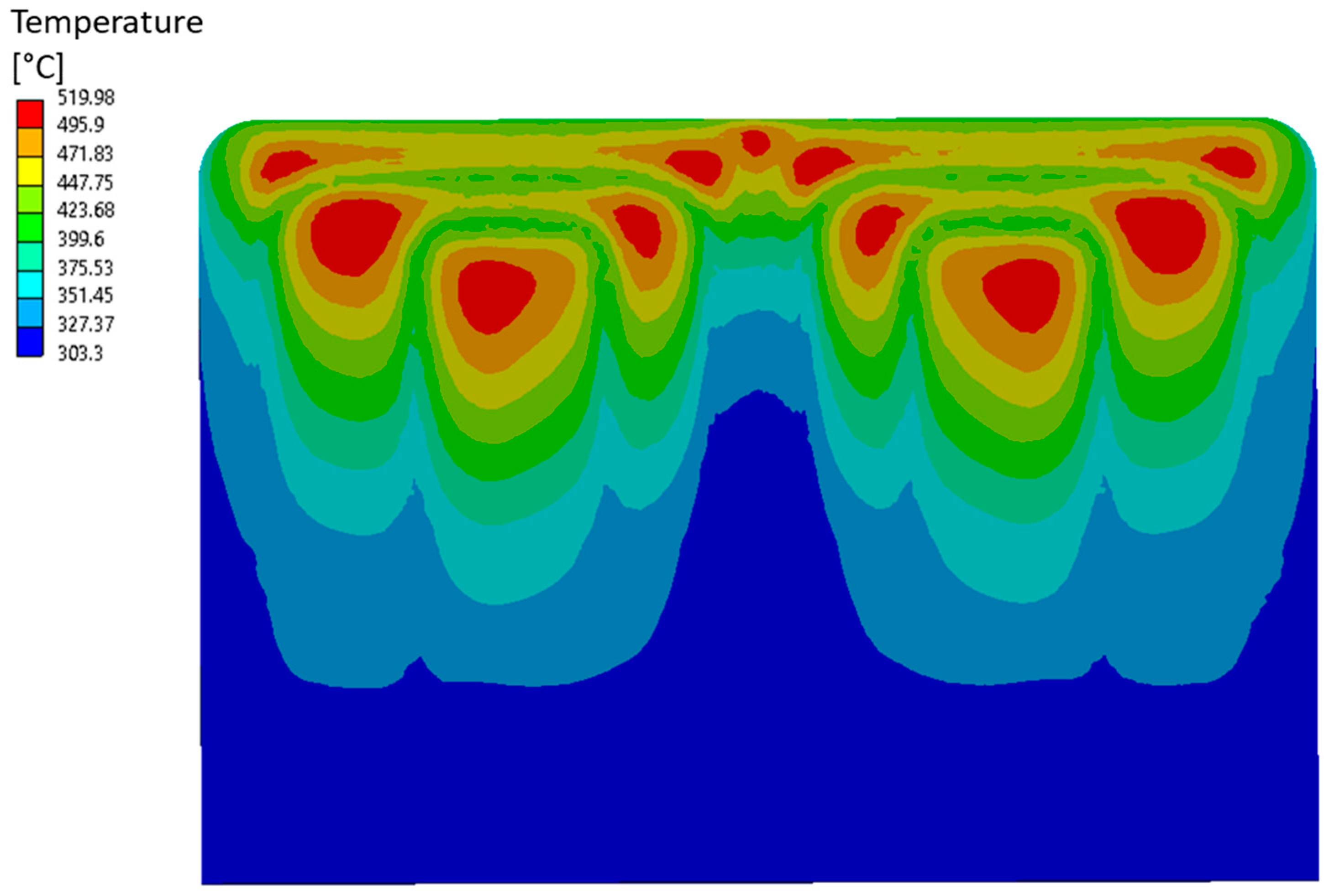
  • Nonuniform heat flux on the Tungsten surface: the value of heat flux at the end of the flat-top for the WCLL COB segment, at the corresponding poloidal region, has been selected in order to take into account the heat flux due to particles and radiation from the plasma. A uniform value of 0.67 MW/m2 [14] has been applied to the straight surface, whereas a cosine-dependent law has been assumed for the bend tungsten surfaces to consider a decreasing value from the uniform one to zero.
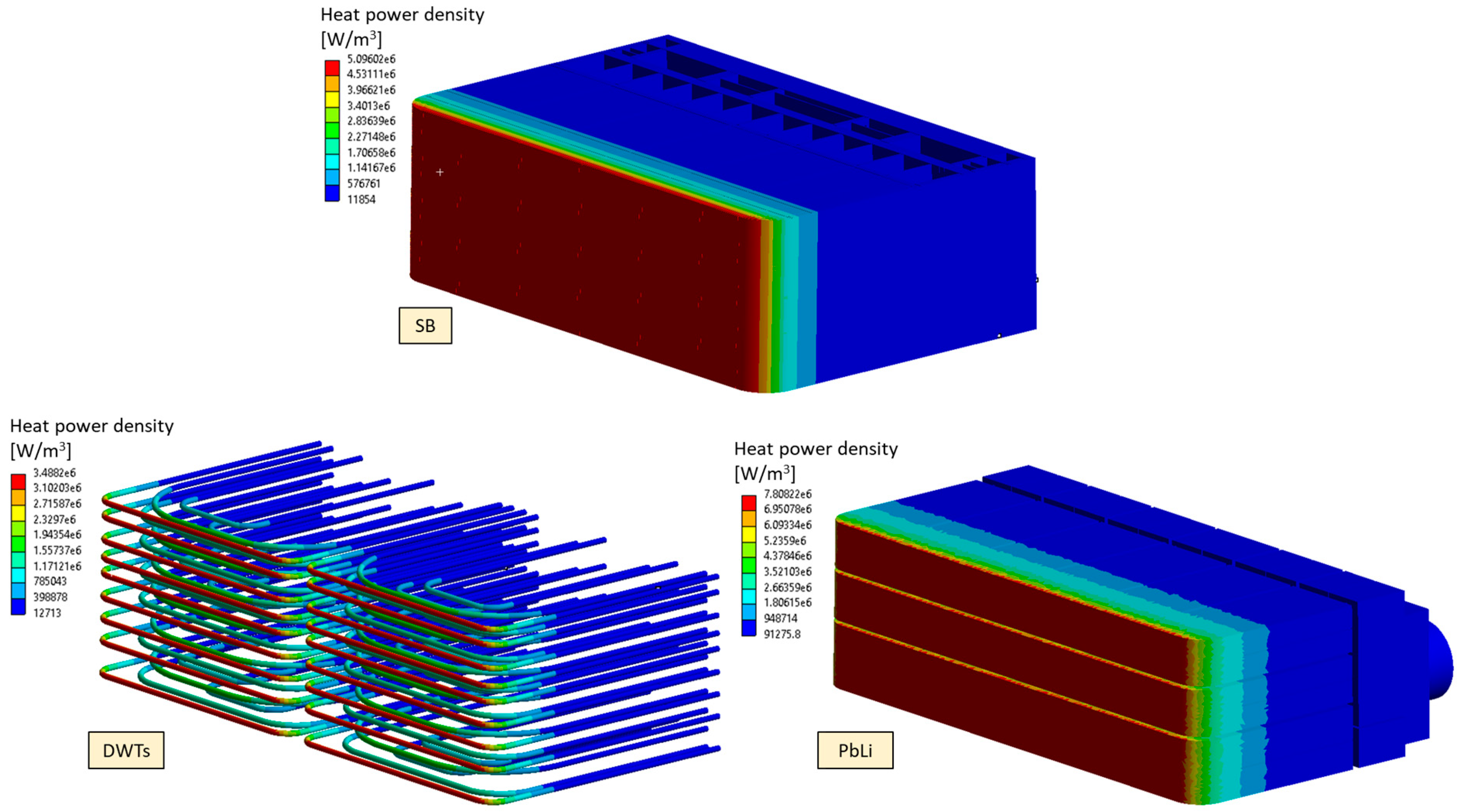
  • Nonuniform nuclear power density: In order to consider the heat power deposited by neutrons and gamma photons, a 3D nonuniform spatial distribution of volumetric heat power density has been applied to the entire model, properly considering the Eurofer, Tungsten, PbLi, and water contribution, drawn from [15] and reported in Figure 11.
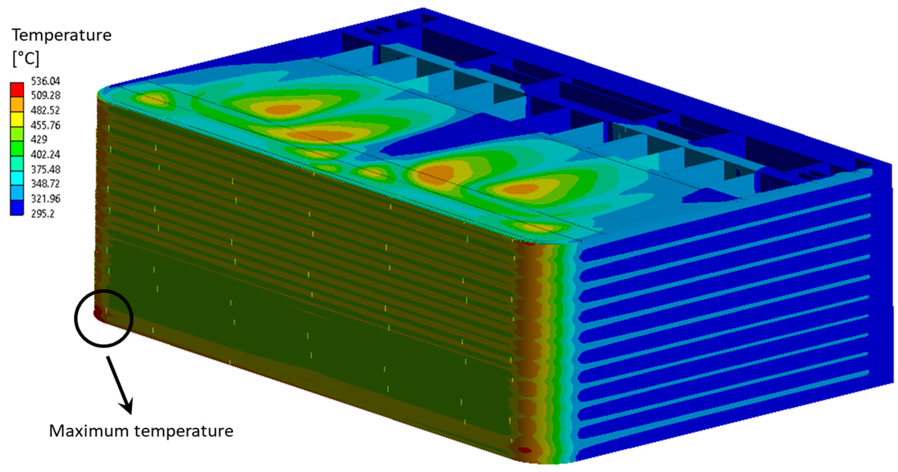
  • Imposed temperature on the water manifolds: Because the water manifolds region is currently in a design phase and, in this configuration, does not allow the DWTs to be properly housed, a uniform temperature equal to 315 °C has been set directly derived from the thermal analysis of that poloidal COB region [9].
  • Convective heat transfer between cooling water and cooling channels and DWTs: A forced convective heat transfer condition between coolant and internal surfaces of both FW-SWs cooling channels and DWTs has been imposed. In order to reproduce the coolant flow, the “thermal fluids” approach, available in the Ansys Steady-State Thermal module, has been adopted. The coolant flow direction has been properly modelled considering the counter-current flow of the cooling channels and the flow path, comprehensive of the recirculation system, of the DWTs water. Thanks to this approach, it is possible to model the fluid flowing within each channel and/or tube by means of a 1-D body, which is discretised and coupled to the nodes of the channel/tube surfaces by means of a convective boundary condition. Therefore, the fluid mass flow per unit area, the Heat Transfer Coefficient (HTC) and the bulk inlet temperature are assigned to each thermal fluid and the bulk temperature profile along the line is calculated and used for the convective boundary condition application. A first attempt value of mass flow rate, derived from [9], has been considered, and the corresponding HTC value has been calculated by means of Dittus & Boelter correlation, considering a water temperature difference (ΔT) between inlet and outlet of 33 °C. The final HTC and mass flow rate values ensuring the imposed ΔT have been calculated by means of an iterative approach. In Table 3, the values of HTC used in the last iteration are reported for the complex of cooling channels and DWTs, where HTCCC, HTCDWTs and HTCDWTs,rec indicate the HTC values used for the cooling channels, first group of DWTs and recirculation DWTs, respectively.
With regards to the structural analysis, as for the preliminary analysis of the BC region, its behaviour has been investigated under both nominal and accidental loading conditions, i.e., the NO and OP loading scenarios. Therefore, the related set of loads and boundary conditions has been applied, already presented in Section 3.1.1. Differently from the preliminary analysis, the EM loads have also been considered. In particular, only the ferromagnetic contribution has been applied because Lorentz’s forces are negligible for NO and OP loading scenarios. In particular, the EM loads calculated by means of a dedicated electro-magnetic analysis [16,17] have been applied to the BC region FEM model thanks to a proper computational procedure.

4.1.2. Results

Firstly, the thermal analysis of the entire BC region has been performed, with the aim of ensuring that the thermal requirements, namely that the Eurofer temperature stays below 550 °C, are fulfilled. In Figure 12, the thermal field arising within the Eurofer domain is reported. As can be observed, the temperature remains below the suggested limit, reaching a maximum value of 536 °C at the FW-SWs bend regions in the bottom part, in correspondence with the Cap plate. Globally, high temperatures can be observed in the FW-SWs bend region due to the cooling channels layout. In particular, the bending radius should be properly tuned in order to minimise the distance of the channel from the Tungsten layer. Finally, no issues can be observed within the Cap plate, as reported in Figure 13, reaching a maximum temperature value of about 520 °C.
Then, the steady-state structural analyses of the entire BC region were performed under the NO and OP loading scenarios, and the fulfilment of the RCC-MRx design criteria were checked. In Figure 14 and Figure 15, the Von Mises equivalent stress fields arising within the structure are reported. Globally, the structure appears to be more stressed in the FW region and, in particular, in correspondence with the two bends. Instead, looking at the OP scenario, the vertical SPs of the last elementary cell, housing the BC plate, experience high stress values. In any case, it has to be underlined that the high stress values predicted in correspondence of the BC plate/SPv interface may be affected by the adopted modelling strategy, foreseeing a simple “bonded” contact without any condition on the mesh continuity. The same modelling strategy has been considered for the FW-SW/BC plate interface. Moreover, as can be observed, there are some stress hotspots due to the local application of the EM loads. Those regions have not been evaluated from the structural point of view, and no paths have been considered near them.
A stress linearisation procedure was performed along the selected paths, and the RCC-MRx criteria, related to Level A and D, for the NO and OP loading scenario, respectively, were checked. In particular, 20 paths were considered within the FW region (Figure 16), 13 paths within the SPs and 3 along the Cap plate (Figure 17 and Figure 18). Looking at the results within the paths considered along the FW and the Cap (Table 4 and Table 5), some issues can be observed within the Cap and in the so-called path AB at every poloidal height (A, B and C). Because the not-matched criteria are those involving secondary stress, it is quite possible that a slight revision of the FW-SW cooling system will have to be performed. However, because these verifications are narrowly failed, this possible improvement is judged to be of the second order, and it can be postponed to a further phase. Instead, as to the SPs results reported in Table 6 and Table 7, besides the criticalities due to secondary loads, it is possible to observe that globally, the Level D criteria are not fulfilled, especially the criterion against the Immediate Excessive Deformation (Pm/Sm), suggesting a revision of the SPs’ thicknesses.
Therefore, as already achieved in the TC region design [4], the thickness of both the vertical and horizontal SPs of the last cell has been increased, moving to 14 and 12 mm, respectively.

4.2. The Second Update (v2) of the BC Region Design

Starting from the results of the first BC region configuration, in this section, the second update of the BC region is reported, properly discussing the modelling approach, the considered loads, boundary conditions and the obtained results.

4.2.1. The FEM Model

Starting from the results of the analysis already presented and following the same approach already used for the TC region design analyses [4], a BC region layout has been set up by increasing the SPs thickness of the elementary cell housing the BC plate, as reported in Figure 19. Then, a 3D FEM model was set up for the thermal analysis and a spatial grid composed of ~3.8 M nodes connected into ~1.7 M tetrahedral and hexahedral elements has been built-up, whereas, as to the structural analysis, since the PbLi, the DWTs and the cooling water flowing within the cooling channels and the DWTs have not been directly modelled, a mesh of ~2.5 M nodes connected into ~650 k tetrahedral and hexahedral elements has been set-up.
The same set of loads and boundary conditions already seen in Section 4.1.1 has been implemented in the up-to-date model with the aim of performing its complete thermo-mechanical analysis under NO and OP steady-state loading scenarios.

4.2.2. Results

Thermal analyses of the BC region v2 have been launched in order to obtain the thermal field arising within the structure characterised by the above-mentioned potential improvements. As can be observed in Figure 20, a thermal field similar to that obtained in the previous configuration has been found, with the same hotter region in correspondence to the FW bends. In any case, the thermal requirement is fulfilled because the temperature is still below the Eurofer suggested limit of 550 °C.
Afterwards, the steady state structural analyses of the BC region, under both the NO and OP loading scenarios, have been launched. Results, in terms of Von Mises equivalent stress field, are reported in Figure 21 and Figure 22 for the two scenarios. In particular, no significative differences can be highlighted with respect to the analysis of the BC region v1, with high values near the FW bends in both scenarios and in the lower part of the FW for the OP scenario.
A stress linearisation procedure has been performed along the same paths already shown in Figure 16, Figure 17 and Figure 18, so the results of the verification of the RCC-MRx design criteria can be compared between the two configurations. Minor improvements can be noticed by a review of the results, but the criteria mostly fail along the same paths and for the same criteria in which they were not fulfilled in the previous configuration. The results are not reported for the sake of brevity because the obtained values are similar to that found for the previous layout assessed. Therefore, it can be concluded that the introduced modifications, namely the thickening of both the vertical and horizontal SPs, did not produce any appreciable benefit to the structural response of the BC region.
However, a more detailed investigation has been conducted for some paths where the criteria were not fulfilled. In particular, the aim was to ensure that such high stress values in a certain region of the structure, originating the high values in the analysed criteria, were not influenced by localised phenomena such as local discontinuities, generating peak stresses, modelling strategies or singularities. Therefore, as deducible from the SDC-IC structural design code [18], a series of paths, placed within a certain range with respect to the potential localised phenomenon, have been selected, and the stress linearisation procedure has been performed for each of them. In particular, the range for the selection of the paths has been chosen equal to twice the thickness of the reference path. Since the purpose of this work is to carry out an exploratory study of the BC region, this procedure has been performed for some paths where the criteria reach high values and fall within the region housing the Cap: SPv1_C, SPv2_C, SPv3_C, AB_Cap1, AB_Cap2, AB_C1 and AB_C2. In Figure 23, an example of the selected set of paths for the path SPv1_C is reported. Then, the stress linearisation procedure has been carried out along all the selected sets of paths. For each set of paths, the average value of each stress tensor component has been calculated, and finally, the Von Mises equivalent stress value has been obtained on the basis of the averaged tensor components. The so-calculated equivalent stress values have been compared with the maximum allowable values prescribed by the RCC-MRx code for each criterion. Since these limits are dependent on the average path temperature, for each criterion, the stress limits have been calculated on the basis of the average temperature of each set of paths.
In Table 8 and Table 9, the results of the RCC-MRx criteria when the equivalent stress is calculated along the reference path and as the average value of the set of paths are reported for the SPv, FW, and Cap. Moreover, the results have been compared, and the percentage of variation, calculated as, for example, (SPv1_Cave − SPv1_C)/SPv1_Cave, is also reported.
Looking at the results along the SPv paths globally, it can be observed that the average values obtained are lower than the reference ones. This behaviour indicates that the local phenomenon, which in this case is the strategy adopted to model the contact between the SPs and the Cap, actually affects the structural behaviour in those regions. The same statement cannot be said, however, looking at the paths individuated along the FW and Cap. In these cases, in fact, the average and the reference path values of the ratio are equal or even worse, which suggests that the structural response is not influenced by any singularities or any localised peak of stress.
Finally, it can be concluded that, as for the SPs’ structural behaviour, particular attention has to be paid to the modelling strategy in order to prevent this interfering with their performances. In any case, additional improvements to the geometric layout should also be helpful to further enhance the structural behaviour so that the RCC-MRx criteria are fulfilled with a great margin. Instead, looking at the FW and Cap response, since the results of the RCC-MRx criteria verification show that the criterion taking into account the secondary stresses (namely IPFL, (Pm + Qm)/Sem) is mostly not fulfilled in this region, a slight revision of the FW-SWs cooling system is necessary to obtain a significant performance improvement. Moreover, it can also be observed that the selected Cap thickness of 40 mm may be too high with respect to that of the surrounding components (FW and SPs). Hence, the Cap plate could act as a grip in their respect, preventing thermal expansion and then inducing secondary stress. Hence, since a Cap 40 mm thick ensures the fulfilment of most of the requirements, a possible way to attain a sound geometric layout can foresee a slight increase of the FW thickness in the BC cell and/or a slight reduction of the Cap one so to achieve a trade-off and allowing the thermal expansion of all the components without generating high secondary stress.

5. Conclusions

Within the framework of the research activities regarding the EU DEMO WCLL COB segment, an exploratory research campaign has been launched with the aim of assessing the thermo-mechanical performances of its BC region.
The analysis carried out has allowed us to obtain important outcomes for the follow-up of the design activities. Indeed, it has been confirmed that at least 10 cooling channels are necessary to properly cool down the FW-SW in this region, as well as that no internal channels are necessary to cool down the Cap plate. Moreover, the SPs’ thicknesses seem not to have a remarkable impact on the structural performances of the BC region under both nominal and accidental conditions. In addition, useful information to pave the way for future design activities has clearly emerged from this study.
First, a slight revision of the FW-SW cooling channels could help in smoothing the thermal field predicted within the structure. In particular, the channel bending radius should be modified to avoid the insurgence of hot regions.
Second, the selected Cap thickness of 40 mm is probably too high in comparison to the surrounding components, excessively preventing their thermal expansion and consequently originating high secondary stress. Hence, a trade-off should be found, possibly slightly increasing the FW-SW thickness of the slice housing the BC (as already achieved for the Top Cap region).
Finally, the contact models adopted to simulate the connection between the Cap, the FW-SW, and the SPs should be accurately refined as it could be responsible for numerical singularities in the stress calculations.

Author Contributions

Conceptualization, G.B., I.C. and P.A.; methodology, G.B., I.C., P.A. and P.A.D.M.; investigation, I.C., S.G., A.G. and L.M.; writing—original draft preparation, G.B. and I.C.; writing—review and editing, G.B., I.C. and P.A.D.M.; supervision, P.A., G.B., I.C. and P.A.D.M. All authors have read and agreed to the published version of the manuscript.

Funding

This work has been carried out within the framework of the EUROfusion Consortium, funded by the European Union via the Euratom Research and Training Programme (Grant Agreement No 101052200—EUROfusion). Views and opinions expressed are, however, those of the author(s) only and do not necessarily reflect those of the European Union or the European Commission. Neither the European Union nor the European Commission can be held responsible for them.

Institutional Review Board Statement

Not applicable.

Informed Consent Statement

Not applicable.

Data Availability Statement

Data will be provided on request.

Acknowledgments

Authors warmly thank Alessandro Tassone, from the Sapienza University of Rome, for the fruitful exchanges and discussion about the conceptualization of the work.

Conflicts of Interest

The authors declare no conflict of interest.

References

  1. Boccaccini, L.; Arbeiter, F.; Arena, P.; Aubert, J.; Bühler, L.; Cristescu, I.; Del Nevo, A.; Eboli, M.; Forest, L.; Harrington, C.; et al. Status of maturation of critical technologies and systems design: Breeding blanket. Fusion Eng. Des. 2022, 179, 113116. [Google Scholar] [CrossRef]
  2. Donnè, T. European Research Roadmap to the Realisation of Fusion Energy; EUROFUSION: Garching, Germany, 2018; ISBN 9783000611520. [Google Scholar]
  3. Forte, R.; Arena, P.; Bongiovì, G.; Catanzaro, I.; Del Nevo, A.; Di Maio, P.; Tomarchio, E.; Vallone, E. Preliminary design of the top cap of DEMO Water-Cooled Lithium Lead breeding blanket segments. Fusion Eng. Des. 2020, 161, 111884. [Google Scholar] [CrossRef]
  4. Bongiovì, G.; Giambrone, S.; Catanzaro, I.; Di Maio, P.A.; Arena, P. Thermo-Mechanical Analysis and Design Update of the Top Cap Region of the DEMO Water-Cooled Lithium Lead Central Outboard Blanket Segment. Appl. Sci. 2022, 12, 1564. [Google Scholar] [CrossRef]
  5. Arena, P.; Del Nevo, A.; Moro, F.; Noce, S.; Mozzillo, R.; Imbriani, V.; Giannetti, F.; Edemetti, F.; Froio, A.; Savoldi, L.; et al. The DEMO Water-Cooled Lead–Lithium Breeding Blanket: Design Status at the End of the Pre-Conceptual Design Phase. Appl. Sci. 2021, 11, 11592. [Google Scholar] [CrossRef]
  6. Melchiorri, L.; Arena, P.; Giannetti, F.; Siriano, S.; Tassone, A. CFD Analysis and Optimization of the DEMO WCLL Central Outboard Segment Bottom-Cap Elementary Cell. J. Nucl. Eng. 2022, 3, 409–420. [Google Scholar] [CrossRef]
  7. AFCEN. RCC-MRx, Design and Construction Rules for Mechanical Components of Nuclear Installations; AFCEN: Paris, France, 2013. [Google Scholar]
  8. DEMO1 Reference Design—2017 March (“EU DEMO1 2017”)—PROCESS Two Page Output (2NE9JA v1.0) (Current). Available online: https://idm.euro-fusion.org/?uid=2NE9JA (accessed on 1 June 2023).
  9. Catanzaro, I.; Bongiovì, G.; Di Maio, P.A. Analysis of the Thermo-Mechanical Behaviour of the EU DEMO Water-Cooled Lithium Lead Central Outboard Blanket Segment under an Optimized Thermal Field. Appl. Sci. 2022, 12, 1356. [Google Scholar] [CrossRef]
  10. Gaganidze, E. Material Properties Handbook—EUROFER97; IDM Ref.: EFDA_D_2NZHBS; Elsevier: Amsterdam, The Netherlands, 2020. [Google Scholar]
  11. Gaganidze, E.; Schoofs, F. Material Properties Handbook—Tungsten; IDM Ref.: EFDA_D_2P3SPL; Elsevier: Amsterdam, The Netherlands, 2020. [Google Scholar]
  12. Spagnuolo, G.A.; Boccaccini, L.V.; Bongiovì, G.; Cismondi, F.; Maione, I.A. Development of load specifications for the design of the breeding blanket system. Fusion Eng. Des. 2020, 157, 111657. [Google Scholar] [CrossRef]
  13. Martelli, D.; Venturini, A.; Utili, M. Literature review of lead-lithium thermophysical properties. Fusion Eng. Des. 2018, 138, 183–195. [Google Scholar] [CrossRef]
  14. Maviglia, F. DEMO PFC Surface Heat Load Specifications; IDM Ref.: EFDA_D_2P985Q v1.8; Elsevier: Amsterdam, The Netherlands, 2020. [Google Scholar]
  15. Arena, P. WCLL BB design activities—2022 ENEA contribution, IDM Ref.: EFDA_D_2QSA7X. Available online: https://idm.euro-fusion.org/?uid=2QSA7X (accessed on 1 June 2023).
  16. Maione, I.A.; Lucca, F.; Marin, A.; Bertolini, C.; Roccella, M.; Villone, F.; Del Nevo, A. Analysis of EM loads on DEMO WCLL breeding blanket during VDE-up. Fusion Eng. Des. 2018, 136, 1523–1528. [Google Scholar] [CrossRef]
  17. Maione, I.A.; Roccella, M.; Marin, A.; Bertolini, C.; Lucca, F. A complete EM analysis of DEMO WCLL Breeding Blanket segments during VDE-up. Fusion Eng. Des. 2019, 146, 198–202. [Google Scholar] [CrossRef]
  18. ITER Structural Design Criteria for In-Vessel Components (SDC-IC) Code. Available online: https://www.yumpu.com/en/document/view/17531325/iter-structural-design-criteria-for-in-vessel-components-sdc-ic (accessed on 1 June 2023).
Figure 1. WCLL COB segment architecture.
Applsci 13 09812 g001
Figure 2. WCLL COB reference BC region.
Applsci 13 09812 g002
Figure 3. WCLL COB reference BC region thermal field.
Applsci 13 09812 g003
Figure 4. Displacement field applied onto the upper surface in NO and OP analyses.
Applsci 13 09812 g004
Figure 5. Von Mises stress field under NO and OP loading scenario. Reference BC region v0.
Applsci 13 09812 g005
Figure 6. Selected paths within SPs and Cap.
Applsci 13 09812 g006
Figure 7. Selected paths within FW.
Applsci 13 09812 g007
Figure 8. Reference BC region v0 vs. v1.
Applsci 13 09812 g008
Figure 9. Von Mises stress field under NO and OP loading scenario. Reference BC region v1.
Applsci 13 09812 g009
Figure 10. Updated BC region v1.
Applsci 13 09812 g010
Figure 11. Volumetric heat power density within SB, DWTs and PbLi.
Applsci 13 09812 g011
Figure 12. Thermal field arising within SB. BC region v1.
Applsci 13 09812 g012
Figure 13. Thermal field arising within Cap. BC region v1.
Applsci 13 09812 g013
Figure 14. Von Mises stress field under NO loading scenario. BC region v1.
Applsci 13 09812 g014
Figure 15. Von Mises stress field under OP loading scenario. BC region v1.
Applsci 13 09812 g015
Figure 16. Selected paths within FW. BC region v1.
Applsci 13 09812 g016
Figure 17. Selected paths within SPs. BC region v1—top view.
Applsci 13 09812 g017
Figure 18. Selected paths within SPs. BC region v1—bottom view.
Applsci 13 09812 g018
Figure 19. Updated BC region v2.
Applsci 13 09812 g019
Figure 20. Thermal field arising within SB. BC region v2.
Applsci 13 09812 g020
Figure 21. Von Mises stress field under NO loading scenario. BC region v2.
Applsci 13 09812 g021
Figure 22. Von Mises stress field under OP loading scenario. BC region v2.
Applsci 13 09812 g022
Figure 23. Selected set of paths for SPv1_C.
Applsci 13 09812 g023
Table 1. RCC-MRx Level D criteria verification. Reference BC region v0.
Level D
Pm/Sm(Pm + Pb)/(Keff × Sm)(Pm + Qm)/Sem(Pm + Pb + Q + F)/Set
Path AB_Cap0.8020.7860.4990.170
Path AB_Cap20.8400.8230.6300.194
Path AB_low1.0220.6970.6290.203
Path AB1_low1.0260.7030.8250.244
Path AB1_mid0.7010.5250.3330.116
Path AB1_up0.4090.3060.4400.163
Path CD_low0.8611.0850.5290.169
Path CD1_low0.8951.1100.6840.248
Path CD1_mid0.2680.3520.3640.176
Path CD1_up0.5250.5730.5750.215
Path EF_low0.4160.7490.2720.144
Path EF1_low0.4360.7680.3660.180
Path EF1_mid0.1950.2680.2720.069
Path EF1_up0.3210.3440.3660.145
Path EF2_low0.4501.3020.2930.421
Path SPv1_low1.6501.3520.7820.157
Path SPv1_up1.4871.0100.7910.160
Path SPv2_low1.4971.0160.7710.143
Path SPv2_up1.7521.1720.6840.106
Path SPv3_low1.3170.8800.9960.285
Path SPv3_up1.4180.9511.0520.306
Path Cap10.4431.4160.3900.222
Path Cap20.4851.3370.4050.209
Path Cap30.2631.0620.2010.143
Path Cap40.2400.9010.1480.114
Table 2. RCC-MRx Level D criteria verification. Reference BC region v1.
Level D
PathPm/Sm(Pm + Pb)/(Keff∙Sm)(Pm + Qm)/Sem(Pm + Pb + Q + F)/Set
AB_Cap0.3630.2670.2870.090
AB_Cap20.3360.2690.3310.163
AB_low1.3281.0200.8350.213
AB1_low1.2480.8661.0330.232
AB1_mid0.5760.4720.3600.128
AB1_up0.3140.2250.3620.124
CD_low0.3030.8300.1420.308
CD1_low0.2280.6290.2300.189
CD1_mid0.4290.3530.5320.187
CD1_up0.5010.4480.6110.197
EF_low0.4681.1430.2920.218
EF1_low0.4781.1390.4200.313
EF1_mid0.2650.2120.3600.082
EF1_up0.3070.2810.4020.134
EF2_low0.4190.6800.2590.181
SPv1_low0.7881.0100.4960.160
SPv1_up1.0910.8180.4560.098
SPv2_low0.9400.9550.5130.163
SPv2_up1.2810.8690.3250.050
SPv3_low0.9590.6540.8130.204
SPv3_up1.0560.7250.8650.241
Cap10.4060.7650.3590.149
Cap20.3200.5420.3080.151
Cap30.2090.6260.1720.092
Cap40.1700.5230.1660.075
Table 3. HTC values used for cooling channels and DWTs coolant.
HTCCC
[W/m2∙K]
HTCDWTs
[W/m2∙K]
HTCDWTs,rec
[W/m2∙K]
36,821.214,862.423,255.2
Table 4. RCC-MRx Level A criteria verification within FW and Cap. BC region v1.
Level A
PathPm/Sm(Pm + Pb)/(Keff∙Sm)(Pm + Qm)/Sem(Pm + Pb + Q + F)/Set
Cap10.0750.1450.8340.177
Cap20.0640.0880.5540.101
Cap30.0680.1270.5900.112
AB_Cap10.0630.0731.1840.672
AB_Cap20.0730.0611.0840.698
AB_A10.0980.0720.4590.742
AB_A20.1000.0761.0030.598
AB_B10.1430.1000.4030.817
AB_B20.1140.0871.0750.569
AB_C10.0850.0710.9660.741
AB_C20.0610.0461.2590.589
CD_A10.0640.0600.2130.148
CD_A20.1080.0730.5370.169
CD_B10.0330.0550.3610.168
CD_B20.1050.0740.4390.127
CD_C10.1530.1600.4310.188
CD_C20.0750.0690.5080.181
EF_A10.0560.0510.1210.810
EF_A20.0700.0690.2440.647
EF_B10.0350.0530.1620.833
EF_B20.0630.0610.2270.632
EF_C10.0890.1670.3630.794
EF_C20.0640.0540.3230.613
Table 5. RCC-MRx Level D criteria verification within FW and Cap. BC region v1.
Level D
PathPm/Sm(Pm + Pb)/(Keff∙Sm)(Pm + Qm)/Sem(Pm + Pb + Q + F)/Set
Cap10.2530.4860.5360.141
Cap20.2040.4400.3190.100
Cap30.3120.4900.3830.107
AB_Cap10.4430.7030.8460.435
AB_Cap20.2420.2920.7180.446
AB_A10.4730.4050.2060.581
AB_A20.4390.3700.3960.419
AB_B10.5180.3830.2220.640
AB_B20.4360.3520.4600.398
AB_C10.3630.5550.7190.490
AB_C20.2170.2120.7250.370
CD_A10.3400.2830.2730.164
CD_A20.4360.3220.3690.146
CD_B10.2860.2800.2610.171
CD_B20.3980.3060.3140.098
CD_C10.6300.5520.4560.149
CD_C20.2260.1970.2970.119
EF_A10.2670.1960.1990.647
EF_A20.3150.3660.1660.484
EF_B10.2300.1900.1840.661
EF_B20.2900.3360.1480.467
EF_C10.4640.7530.3760.517
EF_C20.1530.2140.1550.419
Table 6. RCC-MRx Level A criteria verification within SPs. BC region v1.
Level A
PathPm/Sm(Pm + Pb)/(Keff∙Sm)(Pm + Qm)/Sem(Pm + Pb + Q + F)/Set
SPh1_A0.0980.0961.0590.258
SPh1_B0.0290.0921.0990.245
SPh2_A0.0450.0370.7580.151
SPh2_B0.0490.0430.9180.165
SPv1_A0.1440.0980.3260.079
SPv1_B0.1440.0970.5050.121
SPv1_C0.4350.2960.8140.183
SPv2_A0.1400.0950.6220.110
SPv2_B0.1550.1040.5350.094
SPv2_C0.1600.1170.3620.076
SPv3_A0.0490.0350.4970.103
SPv3_B0.0680.0500.4700.095
SPv3_C0.2110.2990.2110.062
Table 7. RCC-MRx Level D criteria verification within SPs. BC region v1.
Level D
PathPm/Sm(Pm + Pb)/(Keff∙Sm)(Pm + Qm)/Sem(Pm + Pb + Q + F)/Set
SPh1_A0.9450.8361.2260.392
SPh1_B0.9230.9121.2220.340
SPh2_A0.5870.4180.7180.156
SPh2_B0.6650.4780.8040.152
SPv1_A0.9740.6510.7750.223
SPv1_B1.0260.6850.9180.263
SPv1_C1.4040.9501.1620.294
SPv2_A1.0800.7300.2660.049
SPv2_B1.1530.7830.3470.064
SPv2_C1.0590.7600.4800.092
SPv3_A0.9280.6810.2340.062
SPv3_B0.9820.6810.2910.062
SPv3_C1.3581.2860.7590.181
Table 8. RCC-MRx Level D criteria comparison within SPv.
Level D SPv1_CSPv1_CaveVar. [%]
Pm/Sm1.2261.141−7.48%
(Pm + Pb)/(Keff∙Sm)0.8430.770−9.49%
(Pm + Qm)/Sem1.0380.957−8.42%
SPv2_CSPv2_CaveVar. [%]
Pm/Sm0.9250.857−7.86%
(Pm + Pb)/(Keff∙Sm)0.6530.590−10.63%
(Pm + Qm)/Sem0.4240.354−19.74%
SPv3_CSPv3_CaveVar. [%]
Pm/Sm1.1741.123−4.56%
(Pm + Pb)/(Keff∙Sm)1.1311.006−12.41%
(Pm + Qm)/Sem0.6600.612−7.86%
Table 9. RCC-MRx Level A criteria comparison within FW and Cap.
Level A AB_Cap1AB_Cap1aveVar. [%]
(Pm + Qm)/Sem1.1401.1531.07%
AB_Cap2AB_Cap2aveVar. [%]
(Pm + Qm)/Sem1.0471.041−0.55%
AB_C1AB_C1aveVar. [%]
(Pm + Qm)/Sem0.9230.9391.66%
AB_C2AB_C2aveVar. [%]
(Pm + Qm)/Sem1.2111.2231.05%
Disclaimer/Publisher’s Note: The statements, opinions and data contained in all publications are solely those of the individual author(s) and contributor(s) and not of MDPI and/or the editor(s). MDPI and/or the editor(s) disclaim responsibility for any injury to people or property resulting from any ideas, methods, instructions or products referred to in the content.

