

Optimization Method of Assembly Tolerance Types Based on Degree of Freedom
Abstract
:1. Introduction
2. Related Work
3. Basic Concepts
3.1. Definition and Representation of DOF of Tolerance Zones
3.2. Definition and Representation of CPDF
4. CPDF for Geometric Functional Tolerancing of Assemblies
4.1. CPDF Acquisition
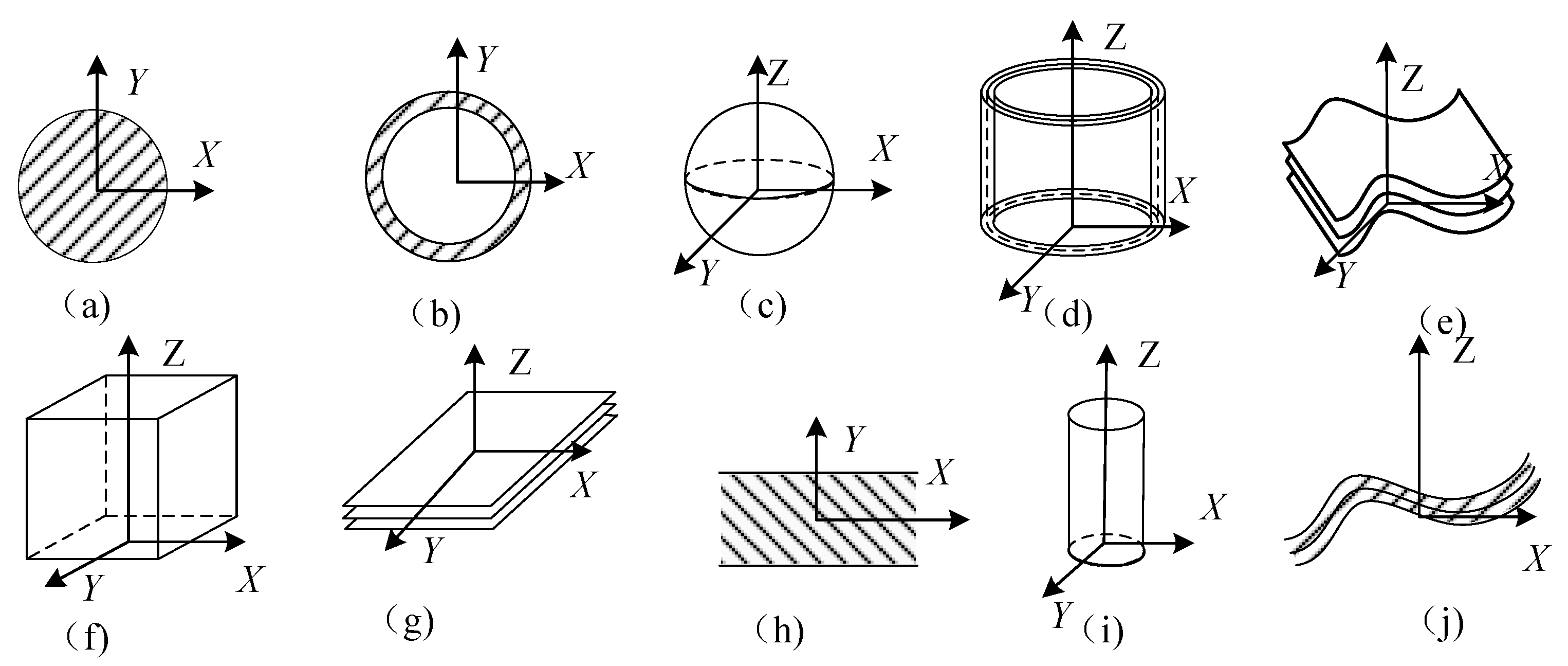
 indicates parallelism, Symbol
  indicates verticality, Symbol
  indicates inclination, Symbol
  indicates degree of coaxiality, Symbol
  indicates total run-out, Symbol
  indicates run-out, and Symbol
  indicates positionality). In the following, the perpendicularity requirement of face-to-face is selected as the research object, and the acquisition process of CPDF is introduced.
4.1.1. Analyze the Geometric Function of the Assembly
4.1.2. Establish an Analytical Coordinate System
4.1.3. Analysis of the Impact of Contact Change Displacement on the Geometric Function
4.2. Summarize the CPDF for Typical Assembly Geometry Functions
indicates parallelism, Symbol indicates verticality, Symbol indicates inclination, Symbol indicates degree of coaxiality, Symbol indicates total run-out, and Symbol indicates run-out.5. A DOF-Based Method for Screening and Optimizing Tolerance Items
5.1. Algorithm for Acquiring CPDF
- Step 1: Analyze the geometric functional requirements of the assembly body, specify the reference datum feature features and the measured feature features of the geometric functional tolerance of the assembly body, and determine the global coordinate system.
- Step 2: Determine the DOF vector of the tolerance zone of the measured feature element and the DOF vector of the reference datum feature element in the assembly.
- Step 3: Calculate the common DOF ; is defined as the result of the Boolean operation between the vector and , and the Boolean operation formula is shown in Equation (13):
- Step 4: Determine the CPDF vector . When the geometric functional tolerance of the assembly is the orientation tolerance, set an auxiliary calculation vector , solving for CPDF , the expression is shown in Formula (14):
5.2. Process for Selecting Tolerance Types of Assembly Features of Assembly Parts
- Step 1: Determine the tolerance zones of different tolerance types of the assembly feature features and their DOFs vector (subscript i is the tolerance mark serial number).
- Step 2: Calculate the Boolean operation value between the DOFs vector Vi and the CPDF vector which can be represented by the vector , is called the comparison freedom vector. Its calculation formula is shown in Formula (16):
- Step 3: Select tolerance types. Judge the relationship between the comparative DOF vector and the CPDF vector . If the CPDF vector is equal to the comparative DOF vector , it indicates that the i-th tolerance type of an assembly feature surface of the assembly part is the preferred tolerance type.
5.3. Establish Algorithm for Automatic Generation of Tolerance Items Based on DOF
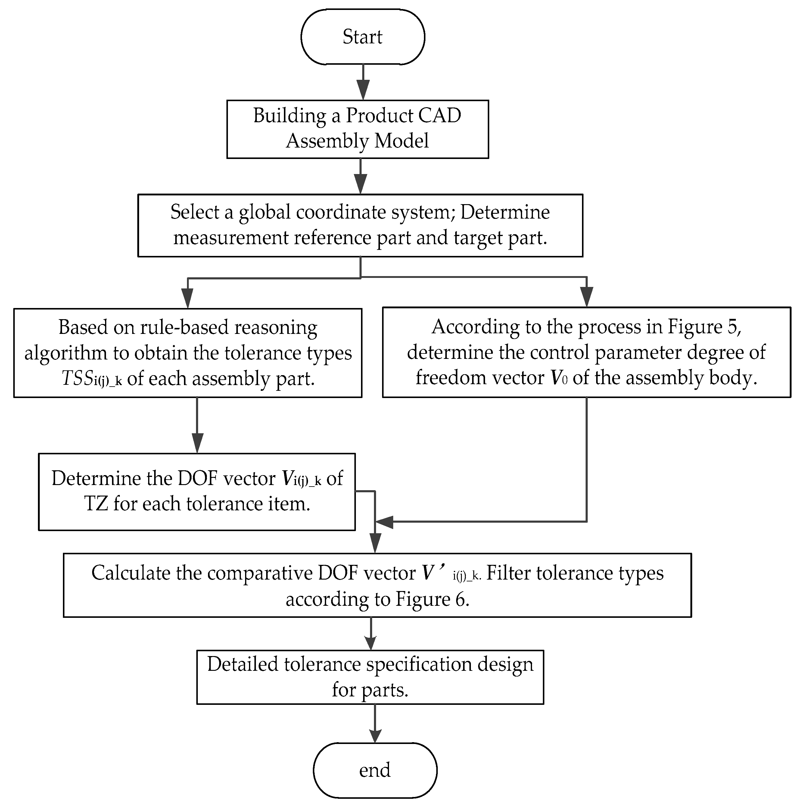
6. Case Study
- Step 1: Construct a CAD three-dimensional assembly model according to the model in Figure 7a.
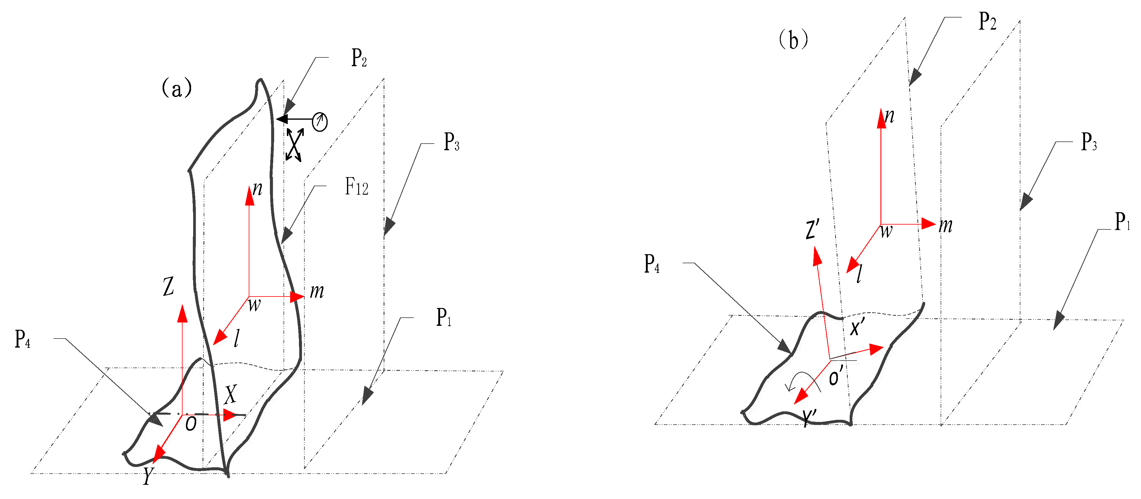
- Step 2: Select the global coordinate system, and select the target part and measurement reference part of the assembly. Considering the convenience of determining the degrees of freedom of the tolerance band, the principle to be followed when establishing the overall coordinate system is as follows: take the measurement reference datum of the geometric function of the assembly as the XY plane, define the X-axis, Y-axis, and the direction perpendicular to the XY plane as the Z-axis. This is shown in Figure 8a. From Figure 8a of the model, it can be seen that the geometric functional requirement of the assembly is the perpendicularity, part P4 is the target part of the assembly, and P1 is the measurement reference part. The measured feature element is the center axis of the cylindrical surface P4S2, and the reference datum element is the plane P1S1 of part P1 as shown in Figure 7b.
- Step 3: According to Figure 5, the CPDF vector of the assembly body is determined.
- Step 4: Select the automatic tolerance generation method based on the rule reasoning algorithm, and deduce the tolerance item of the assembly feature elements of each part. The recent ontology-based automatic reasoning algorithm of Qin et al. [33,34] is a representative automatic generation method of tolerance specifications. In this paper, we choose the automatic generation algorithm of tolerance items proposed in the literature by Qin [33], use Protégé software to construct the tolerance domain knowledge ontology, input the SWRL inference rules, and obtain the automatically recommend tolerance items of each part of the assembly. The assembly constraint relationship of the assembly and the assembly feature surface of each part are marked before automatic reasoning, as shown in Figure 8b. Select part P4 as the representative to carry out tolerance project reasoning, and obtain the markable shape tolerance of the assembly feature cylindrical surfaces P4S1 and P4S2 of workpiece P4. With the central element of feature plane P4S2 as the reference datum, the optional directional position tolerance of the target assembly feature plane P4S1 can be obtained, as shown in Table 3.
- Step 5: Determine the DOF vector of the tolerance zone for all recommended tolerance types of part P4 based on the global coordinate system. Then obtain the DOF vector for all recommended tolerance types based on Table 1 (Note the order of exchanging the DOF and DOI in the DOF vector of the tolerance zone when the coordinate system in the tolerance band in the table is oriented differently from the overall coordinate system.), as shown in Table 4.
- Step 6: Calculate the comparison freedom vectors . Use Equation (11) to perform a Boolean operation on the DOF vector of the tolerance zones and the CPDF vector for different tolerance types; the operation results are shown in Table 3.
- Step 7: Screening optimization of tolerance types. Based on the decision rule of the optimization, the comparison freedom vector of different tolerance types is compared with the CPDF vector =(0 0 0 1 1 0) to obtain the optimization of tolerance types. Through comparison, it can be seen that in the form tolerance class of reference datum feature plane P4S2, the comparison freedom vector of straightness and roundness in the X-Z plane is not equal to the CPDF vector , straightness, or cylindricity in any direction, and the other two form tolerances meeting the geometric functional requirements of the assembly are obtained through screening optimization. The non-reference feature plane P4S1 is optimized to obtain three directional position tolerances, including total run-out, position, and coaxiality, and two form tolerances, including straightness and cylindricity in any direction. It can be seen from the above optimization results of tolerance types that the number of tolerance types is optimized, which not only reduces the recommended number of tolerance items, but also avoids marking unreasonable tolerance types.
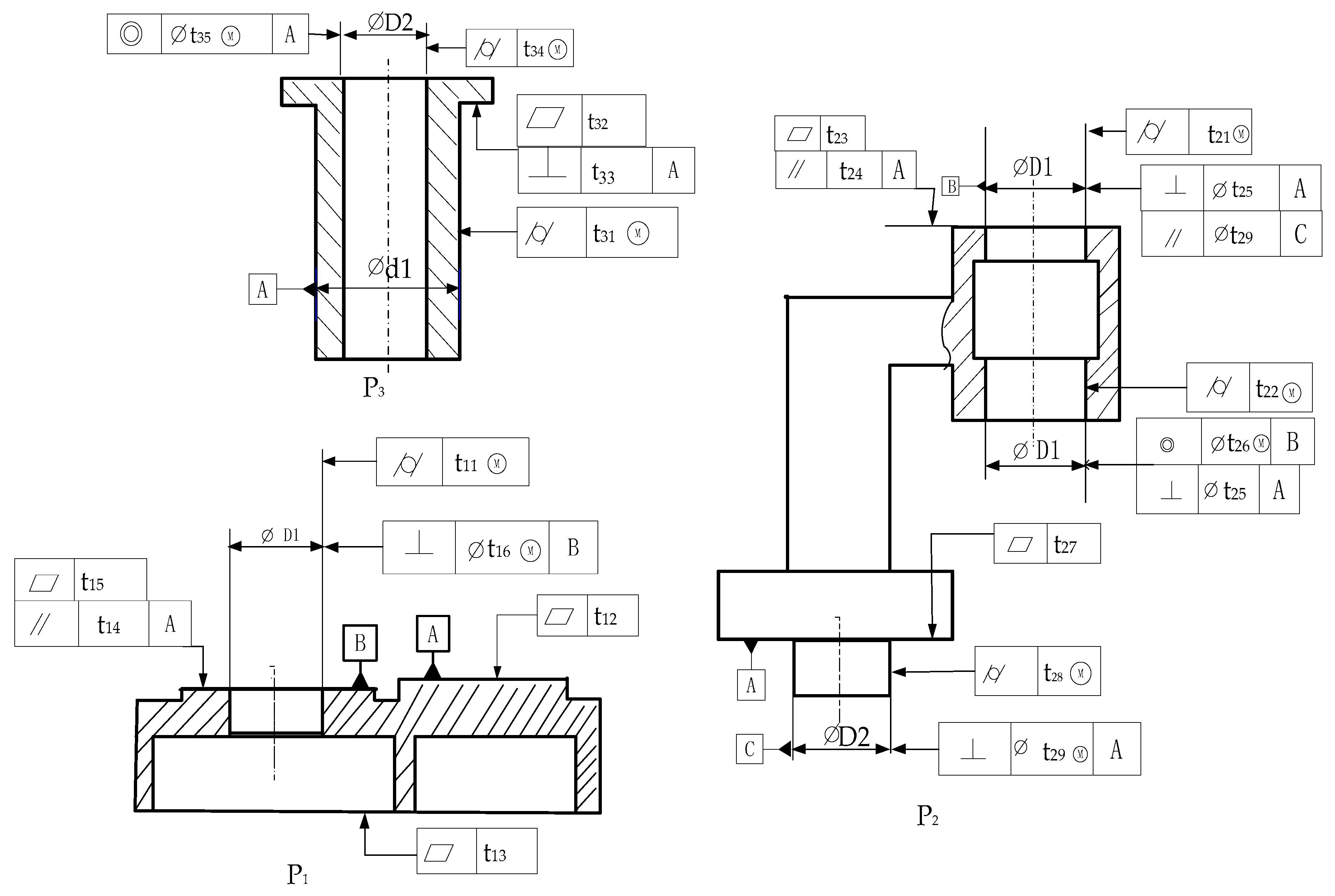
- Step 8: Label the detailed tolerance information of the part. From the optimization results, it can be seen that when the detailed tolerance specifications for part P4 are finally completed, further screening of tolerance types and adding tolerance symbols, such as material conditions and tolerance domain feature symbols [39,40], are needed. According to the fit characteristics and kinematic characteristics of workpiece P4, the assembly feature surface P4S2 is the first assembly datum, and the cylindricity shape tolerance is selected [41]. The feature surface P4S1 is selected as cylindricity shape tolerance and coaxiality tolerance [42], and the final labeling of the tolerances of part P4 is shown in Figure 8. Refer to the determination steps of part P4 for detailed tolerance specifications of other assembly parts to obtain the marked tolerance as shown in Figure 9.
7. Discussion
8. Conclusions
Author Contributions
Funding
Institutional Review Board Statement
Informed Consent Statement
Data Availability Statement
Acknowledgments
Conflicts of Interest
References
- Weill, R.; Clément, A.; Hocken, R.; Farmer, L.E.; Gladman, C.A.; Wirtz, A.; Bourdet, P.; Freckleton, J.E.; Kunzmann, H.; Ham, I.; et al. Tolerancing for Function. CIRP Ann. 1988, 37, 603–610. [Google Scholar] [CrossRef]
- Dantan, J.Y.; Ballu, A.; Mathieu, L. Geometrical product specifications-model for product life cycle. Comput. Aided Des. 2008, 40, 493–501. [Google Scholar] [CrossRef]
- Chen, H.; Jin, S.; Li, Z.M.; Lai, X. A comprehensive study of three dimensional tolerance analysis methods. Comput. Aided Des. 2014, 53, 1–13. [Google Scholar] [CrossRef]
- Kannan, S.M.; Raja Pandian, G. A New Selective Assembly Model for Achieving Specified Tolerance in High Precision Assemblies. Int. J. Precis. Eng. Man. 2020, 21, 1217–1230. [Google Scholar] [CrossRef]
- Zhao, Q.; Li, T.; Cao, Y.; Yang, J.; Jiang, X. A computer-aided tolerance specification method based on multiple attributes decision-making. Int. J. Adv. Manuf. Technol. 2020, 111, 1735–1750. [Google Scholar] [CrossRef]
- Zhang, X.D.; Zhang, C.; Wang, B.; Feng, S.C. Unified functional tolerancing approach for precision cylindrical components. Int. J. Prod. Res. 2005, 43, 25–47. [Google Scholar] [CrossRef]
- Armillotta, A. Tolerance analysis of gear trains by static analogy. Mech. Mach. Theory 2019, 135, 65–80. [Google Scholar] [CrossRef]
- Zhang, Y.; Li, Z.; Gao, J.; Hong, J. New reasoning algorithm for assembly tolerance specifications and corresponding tolerance zone types. Comput. Aided Des. 2011, 43, 1606–1628. [Google Scholar] [CrossRef]
- Qin, Y.; Zhong, Y.; Huang, M.; Liu, F. An assembly tolerance representation model based on spatial relations for generating assembly tolerance types. Proc. Inst. Mech. Eng. Part C J. Mech. Eng. Sci. 2014, 228, 1005–1020. [Google Scholar] [CrossRef]
- Qie, Y.; Qiao, L.; Cui, Y.; Anwer, N. A Doman Ontology for Assembly Tolerance Design. In Proceedings of the 2017 ASME International Mechanical Engineering Conference and Exhibition, Tampa, FL, USA, 3–9 November 2017; Volume 2. [Google Scholar]
- Zhang, Y.; Li, Z.; Wang, J. Hierarchical reasoning model of tolerance information and its using in reasoning technique of geometric tolerance types. In Intelligent Robotics and Applications, Proceedings of the First International Conference, ICIRA 2008, Wuhan, China, 15–17 October 2008; Xiong, C., Liu, H., Huang, Y., Xiong, Y., Eds.; Lecture Notes in Computer Science; Springer: Berlin/Heidelberg, Germany, 2008; pp. 858–868. [Google Scholar] [CrossRef]
- Zhang, Y.; Li, Z.B.; Zhao, L.P. Automatic generation method of assembly tolerance in large-scale assembly design. In Proceedings of the 2009 WRI World Congress on Computer Science and Information Engineering, Los Angeles, CA, USA, 31 March–2 April 2009; Burgin, M., Chowdhury, M.H., Ham, C.H., Ludwig, S., Su, W., Yenduri, S., Eds.; IEEE: Piscataway Township, NJ, USA, 2009; pp. 840–850. [Google Scholar]
- Zhong, Y.; Qin, Y.; Huang, M.; Lu, W.; Gao, W.; Du, Y. Automatically generating assembly tolerance types with an ontology-based approach. Comput. Aided Des. 2013, 45, 1253–1275. [Google Scholar] [CrossRef]
- Qin, Y.; Lu, W.; Qi, Q.; Liu, X.; Huang, M.; Scott, P.J.; Jiang, X. Towards a tolerance representation model for generating tolerance specification schemes and corresponding tolerance zones. Int. J. Adv. Manuf. Technol. 2018, 97, 1801–1821. [Google Scholar] [CrossRef]
- Luo, C.; Franciosa, P.; Mo, Z.J.; Ceglarek, D. A Framework for Tolerance Modeling Based on Parametric Space Envelope. J. Manuf. Sci Eng. 2020, 142, 061007. [Google Scholar] [CrossRef]
- Johannesson, H.; Soderberg, R. Structure and matrix models for tolerance analysis from configuration to detail design. Res. Eng. Des. Theory Appl. Concurr. Eng. 2000, 12, 112–125. [Google Scholar] [CrossRef]
- Hong, Y.S.; Chang, T.C. A comprehensive review of tolerancing research. Int. J. Prod. Res. 2002, 40, 2425–2459. [Google Scholar] [CrossRef]
- ISO 1101:2012; Geometrical Product Specifications (GPS)—Geometrical Tolerancing—Tolerances of Form, Orientation, Location and Run-Out. International Organization for Standardization: Geneva, Switzerland, 2012.
- Krulikowski, A. Fundamentals of geometric dimensioning and tolerancing: Based on ASME Y14.5-2009. In Engineering Design and Rapid Prototyping; Springer: Berlin/Heidelberg, Germany, 2012. [Google Scholar]
- Shen, Y.D.; Shah, J.J.; Davidson, J.K. Feature Cluster Algebra for Geometric tolerancing. In Proceedings of the ASME International Designing Engineering Technology Conferences and Computers and Information in Engineering Conferences, Washington, DC, USA, 28–31 August 2011; Volume 2: Parts A and B, ASME International Design Engineering Technical Conferences/Computers and Information in Engineering Conference (IDETC/CIE). 2012; pp. 709–722. [Google Scholar]
- Khodaygan, S.; Movahhedy, M.R.; Saadat Fomani, M. Tolerance analysis of mechanical assemblies based on modal interval and small degrees of freedom (MI-SDOF) concepts. Int. J. Adv. Manuf. Technol. 2010, 50, 1041–1061. [Google Scholar] [CrossRef]
- Hu, J.; Xiong, G.L.; Wu, Z. A variational geometric constraints network for a tolerance types specification. Int. J. Adv. Manuf. Technol. 2004, 24, 214–222. [Google Scholar] [CrossRef]
- Zhang, J.; Qiao, L.; Huang, Z.; Anwer, N. An approach to analyze the position and orientation between two parts assembled by non-ideal planes. Proc. Inst. Mech. Eng. Part B J. Eng. Manuf. 2021, 235, 41–53. [Google Scholar] [CrossRef]
- Shah, J.J.; Yan, Y.; Zhang, B.C. Dimension and tolerance modeling and transformations in feature based design and manufacturing. J. Intell. Manuf. 1998, 9, 475–488. [Google Scholar] [CrossRef]
- Desrochers, A.; Clemen, A. A Dimensioning and Tolerancing Assistant Model for CAD-CAM Systems. Int. J. Adv. Manuf. Technol. 1994, 9, 352–361. [Google Scholar] [CrossRef]
- Anselmetti, B. Generation of functional tolerancing based on positioning features. Comput. Aided Des. 2006, 38, 902–919. [Google Scholar] [CrossRef]
- Armillotta, A. A method for computer-aided specification of geometric tolerances. Comput. Aided Des. 2013, 45, 1604–1616. [Google Scholar] [CrossRef]
- Cao, Y.L.; Zhang, H.; Li, B.; Wu, Z.; Yang, J. Study on functional specification scheme on interface based on positioning features. Proc. Inst. Mech. Eng. Part B J. Eng. Manuf. 2013, 227, 745–753. [Google Scholar] [CrossRef]
- Ma, N.; Yang, B.; Li, J.; Liu, Y.; Wang, D.; Gao, C. Transfer method of geometric tolerance items based on assembly joints. Int. J. Adv. Manuf. Technol. 2021, 117, 1689–1708. [Google Scholar] [CrossRef]
- Cao, Y.; Zhao, Q.; Liu, T.; Ren, L.; Yang, J. The Strategy of Datum Reference Frame Selection Based on Statistical Learning. J. Comput. Inf. Sci. Eng. 2018, 18, 021002. [Google Scholar] [CrossRef]
- Cui, L.J.; Sun, M.Y.; Cao, Y.L.; Zhao, Q.J.; Zeng, W.H.; Guo, S.R. A novel tolerance geometric method based on machine learning. J. Intell. Manuf. 2021, 32, 799–821. [Google Scholar] [CrossRef]
- Qin, Y.; Lu, W.; Qi, Q.; Liu, X.; Huang, M.; Scott, P.J.; Jiang, X. Towards an ontology-supported case-based reasoning approach for computer-aided tolerance specification. Knowl.-Based Syst. 2018, 141, 129–147. [Google Scholar] [CrossRef]
- Zhong, Y.; Qin, Y.; Huang, M.; Lu, W.; Chang, L. Constructing a meta-model for assembly tolerance types with a description logic based approach. Comput. Aided Des. 2014, 48, 1–16. [Google Scholar] [CrossRef]
- Qin, Y.; Lu, W.; Liu, X.; Huang, M.; Zhou, L.; Jiang, X. Description logic-based automatic generation of geometric tolerance zones. Int. J. Adv. Manuf. Technol. 2015, 79, 1221–1237. [Google Scholar] [CrossRef]
- Qin, Y.C.; Qi, Q.F.; Lu, W.L.; Liu, X.; Scott, P.J.; Jiang, X. A review of representation models of tolerance information. Int. J. Adv. Manuf. Techol. 2018, 95, 2193–2206. [Google Scholar] [CrossRef]
- Zhao, Q.; Li, T.; Cao, Y.; Yang, J.; Jiang, X. A rule-based exclusion method for tolerance specification of revolving components. Proc. Inst. Mech. Eng. Part B J. Eng. Manuf. 2020, 234, 527–537. [Google Scholar] [CrossRef]
- ASME Y14.5.1-2019; Mathematical Definition of Dimensioning and Tolerancing Principles. American Society of Mechanical Engineers: New York, NY, USA, 2019.
- Yang, Z.; Yang, W.; Gao, T.; Zhang, Y. Tolerance analysis method considering multifactor coupling based on the Jacobian-torsor model. Adv. Mech. Eng. 2022, 14, 16878132221140215. [Google Scholar] [CrossRef]
- Zhu, J.; Wang, Y.; Zou, M. An applied methodology for tolerance design based on concurrent engineering. Mech. Sci. 2021, 12, 765–776. [Google Scholar] [CrossRef]
- Lin, W.; Chen, N. Research on New Geometrical Product Specifications (GPS)-Geometrical Tolerancing. In Proceedings of the 5th International Conference on Mechanical, Control and Computer Engineering (ICMCCE), Harbin, China, 25–27 December 2020; pp. 2106–2109. [Google Scholar] [CrossRef]
- Petruccioli, A.; Pini, F.; Leali, F. Tolerance Specification Model for Systematic Application of GD&T in Product Design. In Proceedings of the ASME 2021 International Mechanical Engineering Conference and Expo (IMECE2021), Virtual Online, 1–5 November 2021; Volume 6. [Google Scholar]
- Humienny, Z. Can ISO GPS and ASME Tolerancing Systems Define the Same Functional Requirements? Appl. Sci. 2021, 11, 8269. [Google Scholar] [CrossRef]
- Bettahar, H.; Lehmann, O.; Clévy, C.; Courjal, N.; Lutz, P. Photo-Robotic Extrinsic Parameters Calibration of 6-DOF Robot for High Positioning Accuracy. IEEE/ASME Trans. Mechatron. 2020, 25, 616–626. [Google Scholar] [CrossRef]
- Yan, L.; Yuan, H.; Xu, W.; Hu, Z.; Liang, B. Generalized Relative Jacobian Matrix of Space Robot for Dual-Arm Coordinated Capture. J. Guid. Control Dyn. 2018, 41, 1202–1208. [Google Scholar] [CrossRef]


| Tolerance Code | TS1 | TS2 | TS3 | TS4 | TS5 | TS6 | TS7 | TS8 |
|---|---|---|---|---|---|---|---|---|
| TZ form |  |  |  |  |  |  |  |  |
| DOI | TZ | TX, TY | TX, TY | TZ | TZ | TZ | TZ | |
| RX, RY, RZ | RX, RZ | RZ | RX, RY, RZ | RZ | RZ | RX, RY, RZ | ||
| DOF | TX, TY | TZ, | TZ, | TX, TY, | TX, TY, | TX, TY | TX, TY, TZ | TX, TY, |
| RY | RX, RY | RX, RY, | RX, RY | RX, RY, RZ | ||||
| Representation | Ti (1,1,0) | Ti (0,0,1) | Ti (0,0,1) | Ti (1,1,0) | Ti (1,1,0) | Ti (1,1,0) | Ti (1,1,1) | Ti (1,1,0) |
| Ri (0,0,0) | Ri (0,1,0) | Ri (1,1,0) | Ri (0,0,0) | Ri (1,1,0) | Ri (1,1,0) | Ri (0,0,0) | Ri (1,1,1) |
| Reference Elements | Measured Feature Elements | ||||||||||||
|---|---|---|---|---|---|---|---|---|---|---|---|---|---|
| Line | Plane | ||||||||||||
| Line | | | | | | | |  |  |  |  |  |  |
| Plane |  |  |  |  |  |  |  |  |  | ||||
| Measurement Reference Elements Vf(Tx,Ty,Tz)(Rx,Ry,Rz) | Measured Feature Elements | ||||||
|---|---|---|---|---|---|---|---|
| Line | Plane | ||||||
| Tolerance Zone | DOFs Vt (Tx,Ty,Tz,Rx,Ry,Rz) | CPDF V0 (Tx,Ty,Tz,Rx,Ry,Rz) | Tolerance Zone | DOFs Vt (Tx,Ty,Tz,Rx,Ry,Rz) | CPDF V0 (Tx,Ty,Tz,Rx,Ry,Rz) | ||
 (0,0,1)(1,1,0) (0,0,1)(1,1,0) |  |  | 0,0,1,1,1,0 | 0,0,0,1,0,0 |  | 0,0,1,1,1,0 | 0,0,0,1,1,0 |
 | 1,0,1,1,0,1 | 0,0,0,1,1,0 | |||||
 |  | 1,1,0,1,1,0 | 0,0,0,1,1,0 | ||||
 | 0,1,0,1,0,1 | 0,0,0,1,0,0 |  | 0,1,0,1,0,1 | 0,0,0,1,0,0 | ||
 | 1,0,0,1,1,0 | 0,0,0,0,1,0 |  | 1,0,0,0,1,1 | 0,0,0,0,1,0 | ||
 (1,1,0)(1,1,0) (1,1,0)(1,1,0) |  |  | 1,1,0,1,1,0 | 0,0,0,1,1,0 |  | 0,0,1,1,1,0 | 0,0,0,1,1,0 |
 |  | 0,0,1,1,1,0 | 0,0,0,1,1,0 | ||||
 |  | 1,1,0,1,1,0 | 0,0,0,1,1,0 | ||||
 | 1,1,0,1,1,0 | 0,0,0,1,1,0 |  | 0,1,0,1,0,1 | 0,0,0,1,0,0 | ||
 | 0,1,0,1,0,1 | 0,0,0,1,0,0 |  | 1,0,0,0,1,1 | 0,0,0,0,1,0 | ||
 | 1,0,0,0,1,1 | 0,0,0,0,1,0 | |||||
 | 1,0,1,1,0,1 | 0,0,0,1,0,0 |  | 0,0,1,1,1,0 | 0,0,0,1,1,0 | ||
 | 0,0,1,1,1,0 | 0,0,0,1,1,0 | |||||
| Global Coordinate System | AFS 1 | Serial No | Tolerance Types | TZ Code | DOF of TZ V4(j)_k | Comparison Freedom Vector V′4(j)_k |
|---|---|---|---|---|---|---|
 | P4S1 | 1 | Straightness in any direction ( ) ) | TS4 | 0,1,0,0,1,0 | 0,0,0,0,1,0 |
| 2 | Straightness in X-Y plane ( ) ) | TS1 | 1,1,0,0,0,0 | 0,0,0,0,0,0 | ||
| 3 | Roundness ( ) ) | TS3 | 1,1,0,1,1,0 | 0,0,0,1,1,0 | ||
| 4 | Cylindricity ( ) ) | TS5 | 1,1,0,1,1,0 | 0,0,0,1,1,0 | ||
| 5 | Coaxiality ( ) ) | TS4 | 0,1,0,0,1,0 | 0,0,0,0,1,0 | ||
| 6 | Position ( ) ) | TS4 | 1,1,0,0,0,0 | 0,0,0,0,0,0 | ||
| 7 | Run-out ( ) ) | TS3 | 1,1,0,1,1,0 | 0,0,0,1,1,0 | ||
| 8 | Full runout ( ) ) | TS5 | 1,1,0,1,1,0 | 0,0,0,1,1,0 | ||
| P4S2 | 1 | Straightness in any direction ( ) ) | TS4 | 1,1,0,1,1,0 | 0,0,0,1,1,0 | |
| 2 | Straightness in X-Y plane ( ) ) | TS1 | 0,1,0,0,1,0 | 0,0,0,0,1,0 | ||
| 3 | Roundness ( ) ) | TS3 | 1,1,0,0,0,0 | 0,0,0,0,0,0 | ||
| 4 | Cylindricity ( ) ) | TS5 | 1,1,0,1,1,0 | 0,0,0,1,1,0 |


Disclaimer/Publisher’s Note: The statements, opinions and data contained in all publications are solely those of the individual author(s) and contributor(s) and not of MDPI and/or the editor(s). MDPI and/or the editor(s) disclaim responsibility for any injury to people or property resulting from any ideas, methods, instructions or products referred to in the content. |
© 2023 by the authors. Licensee MDPI, Basel, Switzerland. This article is an open access article distributed under the terms and conditions of the Creative Commons Attribution (CC BY) license (https://creativecommons.org/licenses/by/4.0/).
Share and Cite
Liu, G.; Huang, M.; Chen, L. Optimization Method of Assembly Tolerance Types Based on Degree of Freedom. Appl. Sci. 2023, 13, 9774. https://doi.org/10.3390/app13179774
Liu G, Huang M, Chen L. Optimization Method of Assembly Tolerance Types Based on Degree of Freedom. Applied Sciences. 2023; 13(17):9774. https://doi.org/10.3390/app13179774
Chicago/Turabian StyleLiu, Guanghao, Meifa Huang, and Leilei Chen. 2023. "Optimization Method of Assembly Tolerance Types Based on Degree of Freedom" Applied Sciences 13, no. 17: 9774. https://doi.org/10.3390/app13179774