Article

The Failure Law and Combined Support Technology of Roadways with Weak Surrounding Rock in Deep Wells

1
State Key Laboratory of Mining Response and Disaster Prevention and Control in Deep Coal Mines, Anhui University of Science and Technology, Huainan 232001, China
2
School of Mining Engineering, Anhui University of Science and Technology, Huainan 232001, China
3
Anhui Engineering Research Center of Exploitation and Utilization of Closed/Abandoned Mine Resources, Huainan 232001, China
*
Author to whom correspondence should be addressed.
Appl. Sci. 2023, 13(17), 9738; https://doi.org/10.3390/app13179738
Submission received: 4 August 2023 / Revised: 22 August 2023 / Accepted: 27 August 2023 / Published: 28 August 2023
(This article belongs to the Special Issue State of the Art of Rock Mechanics and Geotechnical Engineering)

Abstract

:
In order to effectively address stability control technology issues of soft surrounding rock roadways in deep mines. This study analyses the deformation and failure characteristics of the surrounding rock of a −962 m horizontal track roadway with original support conditions based on a severe deformation case that occurred in a mine. Upon establishing a mechanical model of surrounding rock failure zoning for circular roadways, which is based on the relationship between the stress–strain curve of soft rocks and the secondary stress distribution and strength of surrounding rock, this study explores the influence of rock strength indicators, disturbance degree, and support resistance on the stress distribution of the surrounding rock. The failure or instability mechanism of high-stress soft and weak surrounding rock is revealed on this basis. A multi-stage strengthening combined support technology is proposed, which consists of “high-strength prestressed anchor bolt (cable) supports as the core, deep and shallow hole groutings as the foundation, bottom angle, and floor anchorage grouting reinforcements as the key.” Moreover, numerical simulation and engineering practice optimize and verify the support scheme. The results show that after adopting the multi-stage strengthening combined support technology, the deformation of the surrounding rock of the roadways was only 12.6~14.3% of that under the original supporting parameters, and the deformation rate was still less than 0.2 mm/d even after 40 days. The proposed surrounding rock support method realizes the stability control of the roadway, which also has specific reference significance for similar projects.

1. Introduction

In China’s proven coal resources, 73% and 53% of the reserves are buried more than 600 m and 1000 m deep, respectively. Such special occurrence conditions require 90% of coal output to be mined in many deep roadways and wells. According to incomplete statistics, state-owned large and medium-sized coal mines in China excavate approximately 8000 km of new roadways yearly [1,2]. As the mining depth increases, the roadways’ surrounding rock and engineering structures are subjected to the harsh “three highs and one disturbance” environment, combined with complex geological structures. Consequently, there are increasing numbers of complex problems, such as continuous and severe deformation of the surrounding rock and serious failure of the supporting structure in soft-rock roadways. The repair rate is as high as 70% or more, which seriously affects the normal use of the roadways [3,4,5]. Therefore, revealing the deformation and failure rules of the roadway surrounding rock and proposing targeted control measures is of great significance for the safety and normal service of such roadways.
In recent years, numerous domestic and foreign scholars have researched the deformation and failure characteristics, control theory, and technology of surrounding rock in high-stress soft rock roadways. Li et al. [6] considered that there are six types of deformation and failure of roadway in a kilometer-deep mine, including roof cracking, floor heaving, unsymmetrical pressure, roof falling, side cracking, and rib spalling. Zhan et al. [7] suggested that the prominent contradiction between high stress and rock mass strength degradation was the intrinsic cause of nonlinear large deformation in deep soft rock roadways. Wu et al. [8] pointed out that the main reason for the tunnel’s serious damage is that the surrounding rock’s rheological deformation intensifies the crack propagation inside the rock. Through numerical simulation, Zhu et al. [9] believed that when the rock mass strength is low, the surrounding rock failure is mainly shear damage, and tensile damage is mainly concentrated at the bottom of the tunnel. In addition, Zhang [10] divided the bearing structure into soft and weak mudstone roadway surrounding rock and proposed the control concept of effective anchoring of anchor rods and anchor cables. Based on the composite beam theory, Liao et al. [11] proposed the control method of layered grouting reinforcement roadway for the problems of surrounding rock fracture development and roof breakage. Peng et al. [12] studied the asymmetric failure characteristics of roadways under high stress through numerical simulation and indoor experiments. They proposed a multi-gradient support method coupling the surrounding rock and supporting structure. Sun et al. [13] developed a high prestress constant resistance large deformation anchor rod support technology. They verified its effectiveness in preventing deformation and failure of soft-rock roadways through field applications. Yang et al. [14] solved the problem of severe deformation of rock due to high stress and long-term immersion in soft-rock roadways by using a joint support technology of “concrete spray layer, high-strength anchor cable, high-strength anchor rod, deep and shallow hole grouting”. Wang et al. [15] analyzed the factors affecting the deformation and failure of loose and fragmented rock roadways surrounding rock instability and proposed a full-section anchoring reinforcement technology. Li et al. [16] proposed a “layer-double arch” load-bearing structure mechanical model based on the characteristics of the first support using anchor net spray support and the second reinforcement using shallow and deep hole grouting anchor rods and anchor cables. Li et al. [17] believed that the main reason for the serious deformation of high-stress soft-rock roadways is the low adhesion between anchoring agents and surrounding rock interface and developed a high-strength grouting anchor rod support technology. Yu et al. [18] conducted in-depth research on fractured rock mass’s deformation and failure characteristics. They proposed a joint control technology based on long and short anchor rod bearing systems and controllable grouting reinforcement of internal and external structures. Zhu et al. [19] proposed a “three-shell” collaborative support technology for the difficult stabilization of large-section roadways in the deep rock mass and verified its effectiveness in controlling the deformation of roadway surrounding rock through numerical simulation and engineering practice. Traditional single support methods are rare in high-stress soft-rock engineering, and combining new support technologies and different support methods is an effective way and trend to solve deep engineering support problems.
In summary, many scholars have analyzed soft-rock roadways’ control mechanisms and countermeasures from different angles and solved various engineering problems. However, on the one hand, due to the complexity and uncertainty of the geological environment and influencing factors of the roadway, the determination of the surrounding rock support method should have the characteristics of adapting to local conditions. On the other hand, the evolution law of surrounding rock stress in deep soft rock roadway and how to construct a more effective and perfect surrounding rock control technology system remain to be discussed.
Therefore, this study comprehensively analyzes the deformation and failure characteristics of surrounding rock in deep soft-rock roadways. Secondly, the three-stage fully stressed-strain curve of soft-rock roadways was used to categorize the secondary bearing structure of the surrounding rock and investigate the failure and stress field distribution characteristics under various influencing factors and the failure evolution mechanism of surrounding rock in high-stress soft rock roadway is revealed. On this basis, a multi-stage strengthening combined support technology was proposed, which utilizes high-strength prestressed anchor rod supports, deep and shallow hole groutings, and anchor reinforcements at the bottom corner and bottom plate. Finally, the reliability of the support scheme is verified using FLAC3D numerical simulation and industrial experimental methods. Figure 1 shows the work performed in this study.

2. Engineering Background

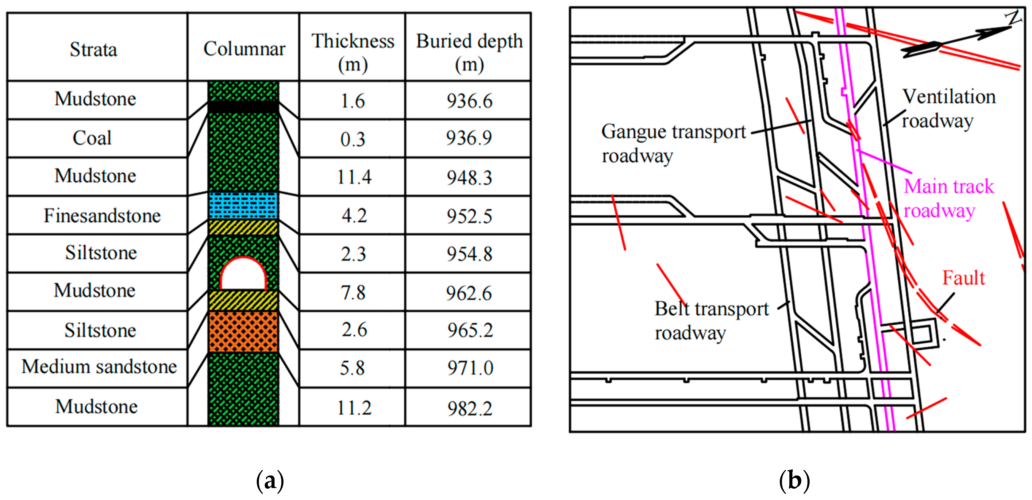
2.1. Geological Conditions

A case study was conducted at a Huainan City, China mine. The mine has a burial depth of approximately one kilometer, and the main track roadway within it has a depth of 962 m. The trackway has a cross-section consisting of a straight wall and semi-circular arch, measuring 5.9 m wide and 4.35 m high, with a net area of around 21.9 m2. At 1100 m across, this trackway is an essential hub for transporting materials, pedestrians, and ventilation across various mining areas on the western side. The section of the trackway being studied runs through mudstone and siltstone layers, encountering several faults and geological structures. As depicted in Figure 2, the stability of the surrounding rock is unsatisfactory, given the prevailing engineering geological conditions.

2.2. Characteristics of Roadway Deformation and Failure

On-site investigations revealed that both the main track roadway and other horizontal roadways at the same level experienced severe instability and support failure during the excavation process. The observed phenomena included: (1) significant convergence deformation of the arch roof of the roadway, accompanied by noticeable uplift and tension cracks on the floor, leading to considerable floor heave; (2) extensive detachment and breakage of the concrete spray layer on its side while the anchor rods were cut, anchor cables sheared, and anchor trays dislodged; and (3) frequent buckling and distortion of local U-shaped steel supports, tearing of metal mesh, and occurrences of rib heave, as shown in Figure 3.
The original support method employed for the main track roadway involved a single application of an anchored wire mesh, as shown in Figure 4a. To assess the specific conditions of deformation and failure in this roadway, select a monitoring section in the experimental section to observe the surface displacement of the surrounding rock using the cross-measurement method. The results are illustrated in Figure 4b, where severe convergence deformation occurred during the first 60 days following roadway excavation, with the deformation increasing consistently over time. The maximum horizontal displacement of both ribs was found to be 258 mm, while the maximum subsidence of the roof reached 369 mm, and the floor heave reached 508 mm. The overall section convergence rate of the roadway exceeded 27.2%, showing evident time-dependent characteristics.

2.3. Analysis of the Failure Factors

The following specific factors were identified as causing deformation and instability of the roadway through on-site investigation and analysis:
(1) High ground stress: The rail roadway has an average depth of approximately 962 m, and the vertical stress is about 24 MPa, indicating that the roadway belongs to the high-stress deep-well roadway category.
(2) Low rock strength: This roadway’s surrounding rock consists of mudstone and fine sandstone rocks. However, core taking at the site showed low core recovery rates, with the retrieved rock cores frequently in the form of cake and short sections. Further mechanical parameters testing indicated uniaxial compressive strengths of 33.7 MPa for mudstone and 52.4 MPa for fine sandstone (Table 1). Moreover, due to high stress and geological structural changes, the surrounding rock’s overall strength was lower, making it susceptible to distinctive plastic deformation during construction, typical of engineering soft rock.
(3) Unreasonable support methods: Inadequate investigation of loose circle range during initial support led to ineffective coupling between the supporting body and the surrounding rock. Engineering analogy methods were used, and an anchor net spray was chosen to reinforce the roadway, resulting in a significantly reduced anchoring capacity of the anchor rods.

3. Stress–Strain Behavior of Surrounding Rock in High-Stress Soft-Rock Roadways

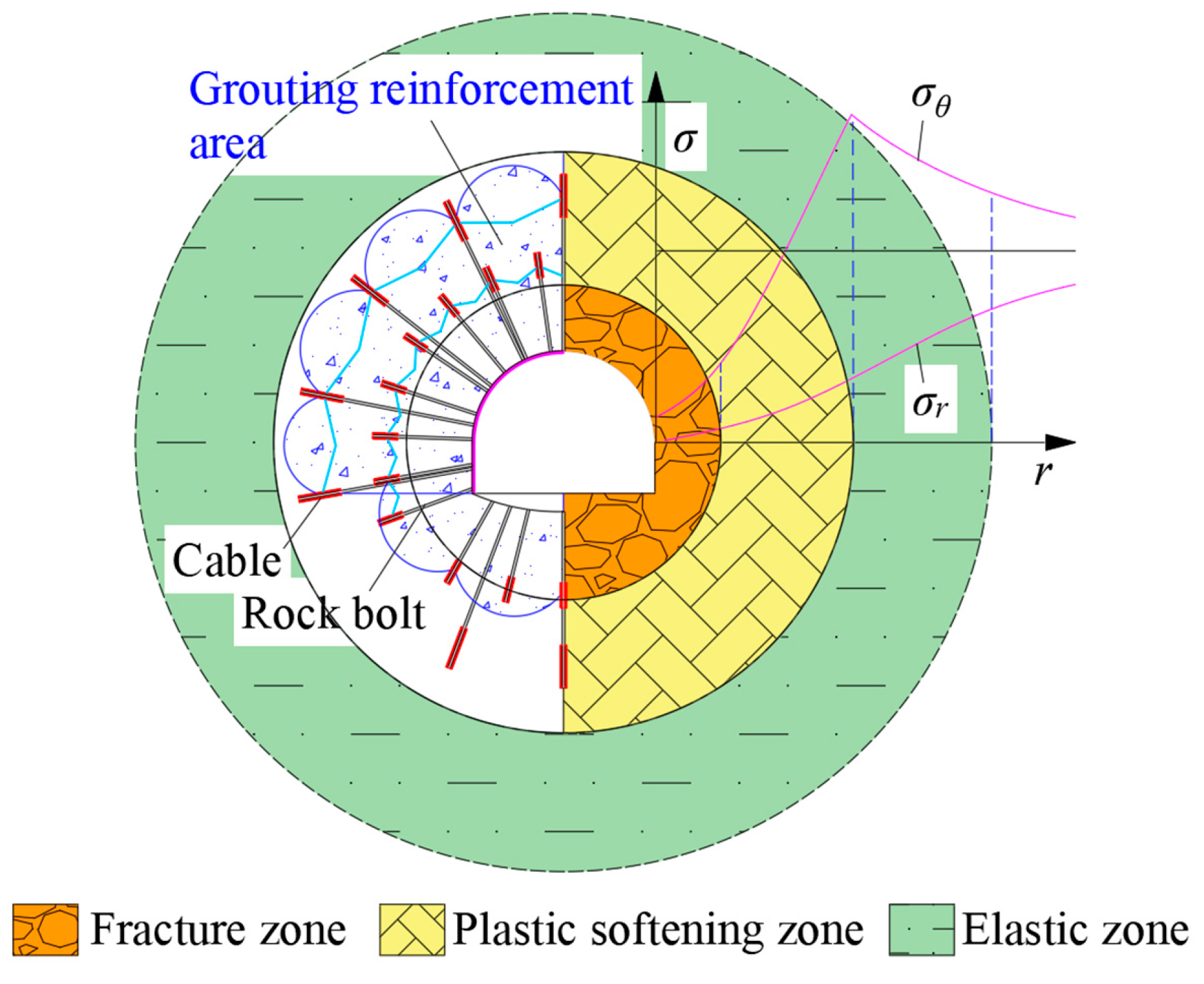
3.1. Mechanical Model of Soft-Rock Roadway

After excavation and unloading, the change in stress loading path causes the surrounding rock to present a state of “unidirectional–bidirectional–tridirectional” stress from the roadway wall outward. This process is characterized by macro-cracking, fissure development, and micro-crack propagation [21]. The behavior of weak rock masses was typically assumed to correspond to the three stages of the complete stress–strain curve of rocks [22]. In this case, the rock mass forms a fragmentation zone, a plastic softening zone, and an elastic zone from the inside out. The mechanical model was built according to these characteristics, as depicted in Figure 5.
Appropriate simplification and assumptions are necessary to facilitate the analysis of the roadway model as follows: (a) the axial length of the roadway is infinite, which can be simplified as a plane strain problem; (b) the roadway is circular, and the radius is equivalent radius to R0 of the semi-circular arch (or rectangular) roadway with a straight wall; (c) the roadway is in the hydrostatic force field; the original rock stress is p0; (d) surrounding rock is a homogeneous and isotropic continuum.
According to the elastic–plastic theory, the equilibrium equation is,
d σ r d r + σ r σ θ r = 0
Its geometric equation is as follows,
ε θ = u r ,   ε r = d u d r
where σr and σθ are the radial and tangential stresses of the surrounding rock, respectively; ɛr and ɛθ are the radial and tangential strain of the surrounding rock, respectively. u is the radial displacement, and r is the radius.

3.2. Deformation and Stress of Roadway Surrounding Rock Mass

(1) Elastic zone
Deformation and stress of surrounding rock in the elastic zones are detailed in [23],
u e = ( 1 + ν ) ( p 0 σ r es ) E R s 2 r
σ r e = p 0 + ( σ r es p 0 ) R s r 2 σ θ e = p 0 ( σ r es p 0 ) R s r 2
where σres is the radial stress at the elastic–plastic junction.
At the elastic–plastic interface (r = Rs), then
σ r es = 2 p 0 σ c q K + 1
K = 1 + sin ϕ 1 sin ϕ
where Rs is the radius of the plastic softening zone (m), σ c q is the ultimate compressive strength of surrounding rock (MPa), σ c q = 2 c cos ϕ 1 sin ϕ , c is the cohesion of surrounding rock, and φ is the initial internal friction angle of the rock (°).
(2) Plastic softening zone
Deformation and stress of surrounding rock in the plastic softening zones are detailed in [23],
u s = ( n 1 1 ) A 0 1 + n 1 r + 2 A 0 R s 1 + n 1 1 + n 1 r n 1
where A 0 = ( 1 + v ) [ p 0 ( K 1 ) + σ c q ] ( K + 1 ) E , E is the elastic modulus of the surrounding rock, ν is the Poisson’s ratio of the surrounding rock, and n1 is the dilatancy coefficient of the surrounding rock in the plastic softening zone.
The Mohr–Coulomb criterion for the plastic softening zone is,
σ θ s = K σ r s + σ c s
Combined with Equations (1) and (8), the general solution of surrounding rock stress can be expressed as,
σ r s = r K 1 σ c s r K d r
where σcs is the compressive strength of the surrounding rock in the plastic softening stage.
If the attenuation form of post-peak plastic softening strength is simplified into a straight line, as shown in Figure 5, then the relationship between the softening strength σcs of rock mass in the plastic softening area of roadway and tangential strain can be expressed as in [10,16],
σ c s = σ c q + σ c b σ c q ε θ sb ε θ es ( ε θ s ε θ es ) = σ c q + σ c b σ c q ( α 1 ) ε θ es ( ε θ s ε θ es )
where σ c b is the residual strength of surrounding rock (MPa); ε θ es , ε θ s , ε θ sb are tangential strains of roadway surrounding rock at the elastic–plastic junction, the plastic softening stage, and the junction of softening and fracture zone, respectively, and α is the softening coefficient.
Then, further combining Equations (2) and (7), here is what can be obtained,
ε θ es = B 1 + B 2
ε θ s = B 1 + B 2 R s r 1 + n 1
ε θ sb = B 1 + B 2 R s R b 1 + n 1
α = ε θ sb ε θ es
where B 1 = ( n 1 1 ) A 0 1 + n 1 , B 2 = 2 A 0 1 + n 1 , Rb is the radius of the fracture zone.
Thus, Equation (10) can be expressed as,
σ c s = σ c q + ( σ c b σ c q ) B 2 ( α 1 ) ( B 1 + B 2 ) R s r 1 + n 1 1 = B 3 R s r 1 + n 1 + B 4
where B 3 = ( σ c b σ c q ) B 2 ( α 1 ) ( B 1 + B 2 ) , B 4 = σ c q B 3 .
Since the stress is continuous, by substituting Equation (15) into Equation (9), the surrounding rock stress can be obtained using the following equation:
σ r s = 2 p 0 σ c q K + 1 + B 3 K + n 1 + B 4 K 1 r R s K 1 B 3 K + n 1 R s r 1 + n 1 B 4 K 1
When r = Rb and σ c s = σ c b , It can be further obtained from Equation (10)
R s R b = 1 + ( α 1 ) ( 1 + n 1 ) 2 1 1 + n 1
(3) Fracture zone
Displacement of the fracture zone is [23],
u b = 2 A 0 ( n 2 n 1 ) ( 1 + n 1 ) ( 1 + n 2 ) R s R b 1 + n 1 + A 0 ( n 1 1 ) 1 + n 1 r + 2 A 0 R b 1 + n 2 1 + n 2 R s R b 1 + n 1 r n 2
where n2 is the expansion coefficient of the fracture zone.
The Mohr–Coulomb criterion for the fracture zone is,
σ θ b = K b σ r b + σ c b
where K b = 1 + sin ϕ b 1 sin ϕ b , σ c b = 2 c b cos ϕ b 1 sin ϕ b ; ϕ b , c b is the residual cohesion and internal friction angle of the rock mass.
Similarly, the general solution of surrounding rock stress obtained simultaneously using Equations (1) and (19) is,
σ r b = r K b 1 σ c b r K b d r
As the residual strength of the fracture zone is a constant, therefore,
σ r b = σ c b 1 K b + C 1 r K b 1
Considering the stress continuity condition at the junction of the fracture zone and the plastic softening zone (when r = Rb, σ r b = ( σ r s ) r = R b ), C1 can be obtained by combining Equation (16) and then substituting it into Equation (18) to further obtain the following Equation (21).
σ r b = r R b K b 1 2 p 0 σ c q K + 1 + B 3 K + n 1 + B 4 K 1 R b R s K 1 B 3 K + n 1 R s R b 1 + n 1 B 4 K 1 σ c b 1 K b + σ c b 1 K b
Upon substituting r = R0 and σrb = Pi into Equation (20), the radius of the surrounding rock’s fracture zone can be obtained as,
R b = R 0 P i σ c b 1 K b / 2 p 0 σ c q K + 1 + B 3 K + n 1 + B 4 K 1 R b R s K 1 B 3 K + n 1 R s R b 1 + n 1 B 4 K 1 σ c b 1 K b 1 1 K b
Finally, the radius Rs of the plastic softening zone can be obtained by combining Equations (17) and (23).

3.3. Physical Parameters of Surrounding Rock

Engineering rock masses are organic complexes composed of rock blocks and structural planes, whose strength characteristics are jointly controlled by various factors, such as the strength of rock blocks and structural planes and the rock mass structure [24]. Properly selecting engineering rock mass parameters is beneficial for making correct judgments about its stability. Especially for weak rock masses with developed fractures, the rock mechanics parameters obtained from laboratory experiments must be appropriately reduced when applied to engineering practice. Therefore, the M-C equivalent strength formula proposed by Hoek based on the H-B strength criterion is adopted to carry out parameter conversion in calculating rock mass strength parameters [25].
c = σ c [ ( 1 + 2 a ) s + ( 1 a ) m b σ 3 n ] ( s + m b σ 3 n ) a 1 ( 1 + a ) ( 2 + a ) 1 + [ 6 a m b ( s + m b σ 3 n ) a 1 ] / ( 1 + a ) ( 2 + a )
ϕ = sin 1 6 a m b ( s + m b σ 3 n ) a 1 2 ( 1 + a ) ( 1 + a ) + 6 ( s + m b σ 3 n ) a 1
E = E i 0.02 + 1 1 + exp 60 G S I 11
where Ei is the elastic modulus of rock.
Where
σ 3 n = σ 3 max / σ c
The relationship between the upper limit of the maximum confining pressure σ 3 max and the strength of rock mass σ cm is as follows,
σ 3 max σ cm = 0.47 σ cm γ H 0.94
where γ is the weight of rock mass, H is the engineering burial depth, σ cm is the strength of rock mass, and the specific expression is as follows,
σ cm = σ c [ m b + 4 s a ( m b 8 s ) ] ( m b / 4 + s ) a 1 2 ( 1 + a ) ( 2 + a )
where σc is the uniaxial compressive strength of rock, mb, s, and a are rock mass parameters of the Hoek–Brown strength criterion, which are determined using the following formula,
m b = m i exp G S I 100 28 14 D s = exp G S I 100 9 3 D a = 1 2 + 1 6 ( e G S I / 15 e 20 / 3 )
where D is the rock disturbance parameter (D = 0, in conventional triaxial compression test), GSI is the geological strength index of rock, which represents the integrity of rock mass, and mi is the rock material index, reflecting the hardness of the rock.
In order to analyze the deformation and failure characteristics of the surrounding rock of the track roadway, the original rock stress p0 was set as 25 MPa according to the in situ stress measured results. The radius of the roadway was the equivalent radius of a semi-circular arch roadway with a straight wall, which can be converted from the following formula [26].
R 0 = k 0 ( S 0 / π ) 1 / 2
where k0 is the correction factor of the semi-circular arch section of the straight wall, k0 = 1.10, S0 is the actual roadway section area, and S0 = 21 m2. The equivalent radius of the roadway R0 = 2.9 m according to Equation (31).
The strength index and disturbance degree of surrounding rock geology in the elastic roadway area are represented by GSIpeak and Dpeak, respectively. In contrast, the surrounding rock in the fractured area is represented by GSIres and Dres, respectively, as shown in Table 2.
The rock mass parameters in Table 2 are substituted into Equation (30), and then the M-C equivalent strength parameters c and φ of rock mass based on the H-B strength criterion can be obtained according to the equivalent strength conversion method of Equations (24)–(29).

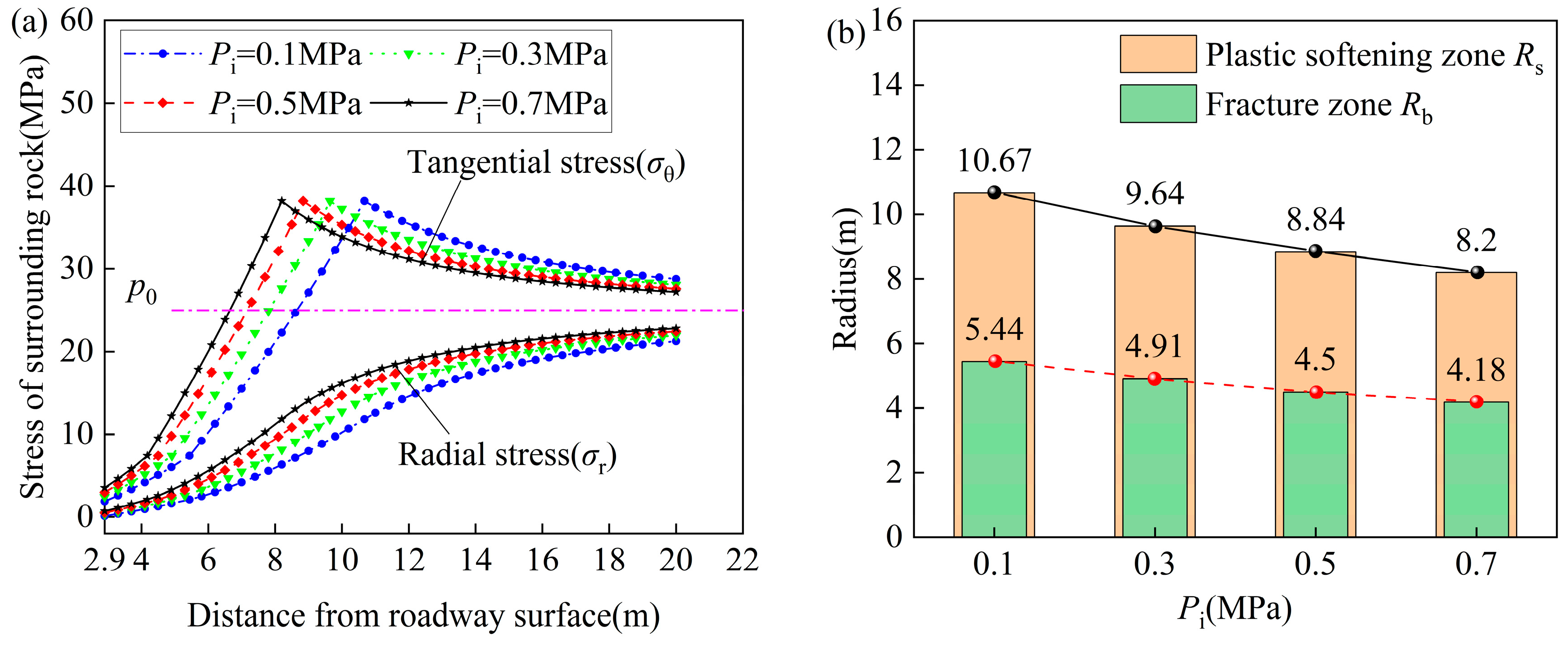
3.4. Analysis of Failure Sensitive Parameters of Surrounding Rock

Taking mudstone as an example, the values of parameters n1 and n2 are taken as 1.2 and 1.3, respectively, α = 4.1, and Dres = 0.7. Figure 6 demonstrates how the residual value of the geological strength index (GSIres) influences the stress and damage range of surrounding rock with various geological strength indicators. It can be observed that the tangential stress distribution pattern of surrounding rock shows an increasing-then-decreasing trend from the roadway surface, with the stress peak occurring at the elastic–plastic boundary. The radial stress keeps increasing and approaches its original state. This phenomenon occurs because, after excavation, the radial stress within a specific range of the surrounding rock surface is relieved. However, due to the disparity between high-concentrated tangential stress and low-strength surrounding rock, the rock mass needs specific fracture damage to balance the impact of high stress. As depicted in Figure 6a, when other parameters remain constant, the peak value of tangential stress transfers deeper into the surrounding rocks as the GSIres of surrounding rocks decrease. In addition, the area around the roadway with lower stress than the original rock stress significantly increases, whereas the slope of the stress gradient tends to slow down.
Furthermore, it can be concluded from Figure 6b that GSIres has a substantial effect on the sensitivity of fracture zone radius (Rb) and plastic softening zone radius (Rs), where their change proportions are approximately exponential as GSIres drop. When GSIres fall from 45 to 15, Rb and Rs increase by 60.4% and 60.7%, respectively. The smaller the GSIres, the more significant the softening degree of surrounding rock, and the lower the self-supporting capacity; hence, the more likely the roadway will become unstable. Improving GSIres for rock mass, particularly in high-stress soft-rock roadways, is essential.
Figure 7 depicts the influence of different disturbance degrees (Dres) on the stress and failure range of surrounding rock. The figure reveals that the extent of disturbance significantly influences the stability of the roadway surrounding rock. Holding other parameters constant, an increase in Dres results in the peak tensile stress zone of the surrounding rocks shifting towards the deeper part, with the radius of the fractured zone (Rb) and the plastic softening zone (Rs) continuously expanding. This phenomenon occurs because a higher degree of disturbance advances the rate of microcrack propagation and fractures/joint surface opening, leading to increased damage and fracture of the rock mass. This renders the rock mass unstable and rapidly propels it into the residual strength stage within a specific range of the surrounding rock. In practical engineering, roadways are prone to various factors, such as blasting excavation, adjacent roadway excavation, and working face advancement, which lead to the continuous deterioration of surrounding rock strength and relaxation of surrounding rock stress. Therefore, the long-term stability of roadways is challenging to ensure. Consequently, an increase in roadway disturbance degree represents one of the primary reasons behind roadway instability and failure.
Figure 8 shows the influence of different support resistance Pi on the stress and failure range of surrounding rock. As shown, the radius of the rock fragmentation zone Rb and the plastic softening zone Rs decrease linearly with increasing Pi. Specifically, as Pi gradually increases from 0.1 MPa to 0.7 MPa, Rb and Rs decrease by more than 23.1%; Rb decreases from 5.44 m to 4.18 m, while Rs drops from 10.67 m to 8.2 m. This finding suggests that the anchor rod’s radial constraint effect can effectively restore the stress state of the surrounding rock from a biaxial or uniaxial force to a triaxial force, reducing the extent of rock crack propagation and significantly enhancing its bearing capacity.
Based on the above analysis, the stability of the surrounding rock of high-stress soft rock roadway is comprehensively controlled by the residual value of geological strength index (GSIres), disturbance degrees (Dres), and support resistance (Pi). Therefore, the stability control of surrounding rock in deep roadway should be aimed at improving the above three parameters.

4. Failure Mechanism and Control Technology of Roadway Surrounding Rock Support

4.1. Support Failure Mechanism of Surrounding Rock

The failure range of the surrounding rock is shown in Table 3, according to the actual geological condition of the track roadway (GSIres = 20, Dres = 0.7, Pi = 0.1 MPa).
The thickness of the fracture zone and the plastic softening zone of the surrounding rock of the track roadway under the original support conditions are 2.54 m and 5.23 m, respectively (shown in Table 3). In the field, the range of fracture and loosening (fracture zone) of the two sides of the track roadway is 2.0~3.0 m using geological radar detection, and the roof is seriously broken, which can reach about 3.4 m locally. The theoretical calculation results are consistent with the field measurement. This indicates that the original support parameters make it difficult to maintain the stability of the roadway for a long time. The fractured rock mass was a loose medium with low bearing strength and could only keep self-stability under frictional occlusion. Microcracks in rock mass in the plastic softening zone are apparent, and their strength is gradually weakened, which, together with the plastic softening zone, it forms the bearing body of the surrounding rock and mainly bears the stress transferred from the reduction in bearing capacity caused by the fracture and relaxation of the roadway surrounding rock. It can be seen that the essence of support is to timely and effectively regulate the dynamic change in stress in the bearing area of surrounding rock through the interaction between support and surrounding rock and change the reduction path of surrounding rock strength. This can prevent the progressive expansion transformation of the boundary of the fracture zone and the plastic softening zone and ensure the stability of the bearing body of the surrounding rock.
However, under the action of high stress, as the residual value of geological strength indicators decreases, the range of the fracture zone in the surrounding rock of the roadway increases, and its ability to resist disturbances weakens. Moreover, when the scope of surrounding rock fragmentation exceeds the anchor rod anchoring section, due to the lower confining pressure within the anchor rod anchoring section, the support resistance provided by the anchor rod in the fractured and low confining pressure surrounding rock is significantly reduced, further exacerbating the deformation and failure of the roadway surrounding rock.

4.2. Support Technology Combined with Multi-Stage Strengthening of Surrounding Rock

The above analysis shows that the mechanical properties of surrounding rock in fracture, plastic, and elastic zones are different, so the required supporting strength is also different. Moreover, the coupling of support and mechanical properties of surrounding rock can effectively improve the geological strength index (GSIres) residual value and reduce the disturbance degrees (Dres). It also helps to give full play to the support resistances (Pi) of the support body. Based on this, we put forward the subsection reinforcement combined support technology with “high-strength prestressed anchor bolt (cable) support as the core, deep and shallow hole grouting as the foundation, bottom angle and floor anchorage grouting reinforcement as the key,” as shown in Figure 9. The principle is as follows:
(1)
Prestressed bolts, steel mesh, and shotcrete support are preferred in the initial support. Among them, the density of bolt support should not be too small, as the “pin effect” of the bolt can transform the cataclastic structure into a cohesive whole structure, significantly improving the surrounding rock’s bearing capacity. In addition, the length of the bolt should not be less than 2.6 m, which is conducive to each bolt exerting a force on the surrounding rock along the length of the bolt, forming a reinforcement zone. All the reinforcement zones are connected, forming a reinforcement ring with an arch effect inside the surrounding rock. It can not only improve its strength and have a self-supporting effect but also provide confining pressure and improve the stress environment of surrounding rock, thus limiting the tangential and radial deformation of surrounding rock.
(2)
High-prestressed long anchor cable should be the primary reinforcement support. The anchorage section of the long anchor cable can extend into the deep, stable surrounding rock with high confining pressure and then transmit the load of the fracture zone to the deep, stable rock layer through suspension. In the fracture zone, the plastic softening zone and elastic zone were connected into a region that expands the bearing range of the surrounding rock and fully mobilizes the overall bearing capacity of the surrounding rock.
(3)
The primary reinforcement support should be full-section multi-stage grouting. It is difficult to prevent the long-term rheology of surrounding rock only by supporting anchor rods and cables in the roadway with high stress and weak surrounding rock. The extensive development of cracks in surrounding rock provides a channel for cement grout to penetrate the surrounding rock. Low-pressure shallow hole grouting can bond and solidify the rock mass in the fractured area, forming a grouting reinforcement ring in the surrounding rock’s shallow part, effectively preventing the grout leakage. The high-pressure deep hole grouting can close the micro-cracks, and the grout diffuses in the cracks in a “network” to form a high-strength skeleton structure, improving the surrounding rock’s shear strength and integrity. At the same time, after the plastic energy of the surrounding rock is released, the key bearing area will move to the depth. The key bearing zone, strengthened by grouting, requires only a tiny compressive expansion force and supporting resistance to maintain roadway stability.
(4)
A high-strength anchorage bearing arch system is formed in broken surrounding rock by high prestressed anchor bolt (anchor cable) support, graded grouting reinforcement, and concrete spray layer. However, the stability of the bearing arch also depends on the strong bottom foundation [27]. The bottom foundation is used to bear the arch leg, and the deformation and malposition of the arch leg will cause instability in the supporting system. The natural strength of floor strata is improved, and the release of horizontal stress is blocked by anchoring reinforcement of the floor and bottom angle. In addition, it can also be connected with the roof support to construct a complete bearing circle, which significantly reduces the deformation velocity of surrounding rock in the stable stage.

5. Field Test and Effect Analysis

5.1. Support Scheme

Based on the deformation characteristics of the surrounding rock of the track roadway and the above theoretical analysis, the test of the graded strengthening combined support scheme was carried out in the repair section of the roadway, as shown in Figure 10. The main supporting parameters are as follows:
(1) Shotcrete support of anchor net. The initial support adopted high-strength steel bolts with Φ 22 × 2800 mm; the interrow spacing was 700 × 700 mm; the preload was not less than 80 kN; the anchoring force was not less than 120 kN. The strength of the concrete was C25, and its thickness of injection was 100 mm; the steel mesh of 100 × 100 mm was laid.
(2) Anchor cable support. The steel strand anchor cable with a 22 × 6300 mm diameter was used to strengthen the support. The interrow distance is 1400 × 1400 mm, and the preload was not less than 140 kN. The anchorage was lengthened using three rolls of Z2865 resin coil.
(3) The deep and shallow holes were reinforced using multi-stage grouting. The reinforcement support adopts deep hole and shallow hole multi-stage grouting reinforcement; shallow hole grouting aperture was 45 mm; hole depth was 2.8 m; row distance was 1400 × 1400 mm; grouting material adopts single-liquid water–cement glass grout, grouting pressure did not exceed 2 MPa. The hole diameter of deep-hole grouting was 28 mm; the hole depth was 5 m; cement grout was used; and the grouting pressure was 3~5 MPa.
(4) Bottom angle and bottom plate anchor reinforcement. First, the bottom plate was undercover into an inverted bottom arch structure; secondly, the self-drilling hollow grouting bolt with Φ 25 mm × 3.5 m and spacing of 1000 mm was selected for the two bottom side angles. The bottom grouting bolt with Φ 25 × 2500 mm, and the spacing between rows was 1000 × 700 mm. Finally, the anchor cable bundle of Φ 17.8 mm × (8~15.5) m high-strength steel strand was applied to the bottom plate, and the spacing between rows was 2000 × 2800 mm.

5.2. FLAC3D Numerical Calculation Verification

5.2.1. Numerical Simulation Model

In order to verify the effectiveness of the combined support technology, a calculation model was established using the finite difference software FLAC3D 5.0 based on the geological conditions of the track roadway. The model size is 50 m × 30 m × 40 m along the X, Y, and Z directions. The roadway shape is a semi-circular arch section, 5.9 m wide and 4.35 m high, as shown in Figure 11. The vertical stress of 25 MPa is applied to the model’s top according to the actual in situ stress measurement results. The lateral pressure coefficient is 1.0 [20]. The boundary conditions around and at the bottom of the model are fixed, and the upper boundary conditions are free.
In order to reflect the softening characteristics of the post-peak strength, the strain–softening constitutive model is adopted in the simulation [6]. This simulation uses the Pile structural unit to simulate the anchor rod, the cable structural unit to simulate the anchor cable, and the liner structural unit to simulate the tray.

5.2.2. Simulation Result Analysis

As shown in Figure 12, the stress level within 4.3 m of both sides of the roadway under the original support is lower than the stress of the original rock. The peak stress of the surrounding rock is located at 6.4 m of the roadway side, and the stress concentration coefficient is 1.6. After multi-stage strengthening combined support, the area below the original rock stress is reduced by 64.6% compared with the original support, and the peak value of surrounding rock stress moves 2.15 m to the roadway surface. The statement suggests that the supporting scheme enhances the stress distribution in the surrounding rock, improves its overall strength, effectively prevents pressure transfer to deeper areas, and contributes to maintaining roadway stability.
The plastic failure range of the roadway is significantly reduced after combined support, as shown in Figure 13. The fracture zone range of the roadway side and roof decreased from 1.75 m to 0.63 m under the original support. In comparison, the floor also decreased from 2.87 m to 2.32 m, with a reduction in the plastic softening zone range. Additionally, there was a decrease in the “Tension” failure area on the roadway surface, indicating effective prevention of tension shear failure of surrounding rock.
From Figure 14, it is evident that the original supporting roadway has undergone significant section deformation. The roof and floor have deformed by 224 mm and 335 mm, respectively, while the two sides have deformed by 243 m. This deformation poses a severe threat to the stability of the roadway. However, after adopting combined support measures, the surrounding rock’s deformation is controlled. The top and bottom plates’ deformations are now at 143 mm and 152 mm, respectively, while that of both sides is 130 mm. Compared with the original support, they are reduced by 36.2%, 54.6%, and 46.5%, respectively. The results show that the combined support method can effectively prevent large deformations of the surrounding rock mass in soft rock.

5.3. Field Verification

No conditions were found at the site, such as broken bolts, falling off cement shotcrete layer, and apparent convergence of surrounding rock. It can be seen from the deformation and failure effect photos of roadway combined support (Figure 15).
In order to further verify the reliability of the combined support technology of the weak surrounding rock roadway in the deep well, two stations (the distance between the stations is 40 m) are arranged in the track roadway, and the surface displacement monitoring is carried out using the cross method. The monitoring results are shown in Figure 16. The overall roadway deformation is small, the maximum two-side displacement of 1# and 2# monitoring points is 38 mm, the maximum roof subsidence is 52 mm, and the maximum floor heave is 64 mm, which is respectively 12.6%, 14.1%, and 14.3% of the original support scheme. The deformation stability stage is entered after 40 d, and the deformation rate is lower than 0.2 mm/d. It is proved that a robust bearing system is formed in the roadway surrounding rock after the combined support scheme was adopted, which realizes the stable control of the roadway with weak surrounding rock in the deep well.

6. Conclusions

(1)
The significant buried depth of the roadway, high ground stress, and complex geological structure significantly reduce the overall strength of surrounding rock, resulting in prominent rheological characteristics and large deformation of surrounding rock. The original supporting mode is too single; forming a high-strength and high-stiffness anchorage system between the supporting body and the surrounding rock is difficult. Meanwhile, neglecting to strengthen the weak parts of the floor also leads to the failure of the surrounding rock to form a complete bearing structure, resulting in severe damage and instability.
(2)
After roadway excavation, the surrounding rock forms the bearing structure of the fractured zone, plastic softening zone, and elastic zone successively from the surface to the inside. The mechanism of significant deformation failure in high-stress soft-rock roadways is that the range of fracture zone and plastic softening zone keeps increasing. It is beneficial to restrain the transfer of surrounding rock stress to the deep and improve the bearing capacity of surrounding rock by increasing the residual value of surrounding rock geological strength index, reducing the disturbance degree of surrounding rock, and ensuring adequate support resistance.
(3)
Based on the geological conditions of the track roadway, the thickness of the fractured zone and the plastic softening zone in the surrounding rock are determined to be 2.54 m and 5.23 m, respectively. On this basis, the multi-stage strengthening combined support technology of “high-strength prestressed anchor bolt (cable) support as the core, deep and shallow hole grouting as the foundation, bottom angle and floor anchorage grouting reinforcement as the key” is put forward. The mechanical mechanism of this support technology is to couple with the mechanical properties of the surrounding rock so that the anchorage system can form a complete and continuous bearing arch structure to ensure the long-term stability of the main bearing body of the surrounding rock.
(4)
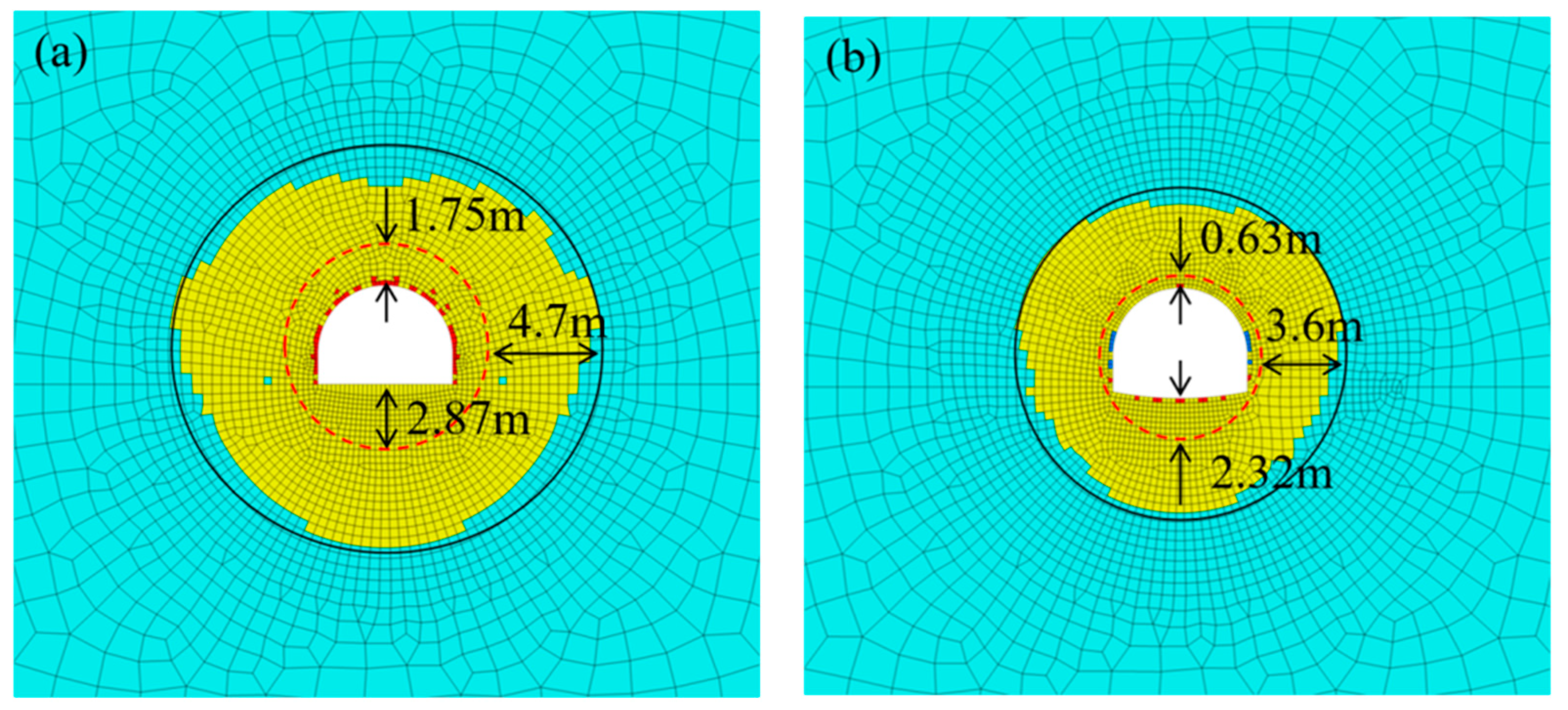
The numerical simulation results show that it is one of the most effective means to control surrounding rock by decreasing the bolt and cable row distance to increase the anchoring area. Compared with the original, the combined support scheme can reduce the tensile stress zone of the roadway surrounding rock and effectively prevent the deformation and failure of the surrounding rock mass. The integrity of the surrounding rock is better when the combined support scheme is adopted, and the roadway deformation is only 12.6–14.3% of that under the original support scheme. In particular, the supporting structure is fully coupled with surrounding rock, and the roadway becomes stable after only 40 days. This effectively solves the control problem of weak surrounding rock in deep wells.

Author Contributions

Conceptualization, X.W. and J.T.; methodology, Y.L.; software, Q.F.; validation, X.W.; formal analysis, J.T.; investigation, Y.L.; resources, J.T.; data curation, Q.F.; writing—original draft preparation, X.W.; writing—review and editing, Q.F.; visualization, J.T.; supervision, Y.L.; project administration, X.W.; funding acquisition, J.T. All authors have read and agreed to the published version of the manuscript.

Funding

This research was supported by the Natural Science Foundation of China (No. 52174102), Key Research and Development Program of Anhui Province (No. 2022m07020007), Natural Science Research Project of Anhui Educational Committee (No. 2022AH050811); University-level Key Projects of Anhui University of Science and Technology (13220485); Scientific Research Foundation for High-level Talents of Anhui University of Science and Technology (2021yjrc30); The Anhui Engineering Research Center of Exploitation and Utilization of Closed/Abandoned Mine Resources (No. EUCMR202204); Major special projects of science and technology in Shanxi Province (No. 20191101016).

Institutional Review Board Statement

Not applicable.

Informed Consent Statement

Not applicable.

Data Availability Statement

The simulation and monitoring data in the article are not freely available due to legal concerns and commercial confidentiality. Nevertheless, all the concepts and proce dures are explained in the presented research and parts of the research may be available upon request.

Conflicts of Interest

The authors declare that they have no known competing financial interests or personal relationships that could have appeared to influence the work reported in this study.

References

  1. Xie, H.; Gao, F.; Ju, Y. Research and development of rock mechanics in deep ground engineering. Chin. J. Rock Mech. Eng. 2015, 34, 2161–2178. [Google Scholar]
  2. Kang, H.; Wang, J.; Lin, J. Case studies of rock bolting in coal mine roadways. Chin. J. Rock Mech. Eng. 2010, 29, 649–664. [Google Scholar]
  3. Yang, S.; Chen, M.; Jing, H.; Chen, K.; Meng, B. A case study on large deformation failure mechanism of deep soft rock roadway in Xin’An coal mine, China. Eng. Geol. 2017, 217, 89–101. [Google Scholar] [CrossRef]
  4. Zhu, Q.; Li, T.; Zhang, H.; Ran, J.; Li, H.; Du, Y. True 3D geomechanical model test for research on rheological deformation and failure characteristics of deep soft rock roadways. Tunn. Undergr. Space Technol. 2022, 128, 104653. [Google Scholar] [CrossRef]
  5. Kang, H.; Jiang, P.; Wu, Y.; Gao, F. A combined “ground support-rock modification-destressing” strategy for 1000-m deep roadways in extreme squeezing ground condition. Int. J. Rock Mech. Min. Sci. 2021, 142, 104746. [Google Scholar] [CrossRef]
  6. Li, G.; Ma, F.; Guo, J.; Zhao, H. Deformation Characteristics and Control Method of Kilometer-Depth Roadways in a Nickel Mine: A Case Study. Appl. Sci. 2020, 10, 3937. [Google Scholar] [CrossRef]
  7. Zhan, Q.; Shahani, N.M.; Zheng, X.; Xue, Z.; He, Y. Instability mechanism and coupling support technology of full section strong convergence roadway with a depth of 1350 m. Eng. Fail. Anal. 2022, 139, 106374. [Google Scholar] [CrossRef]
  8. Wu, B.; Chang, J.; Li, C.; Wang, T.; Shi, W.; Wang, X. Mechanism of Time-Dependent Instability of Deep Soft-Rock Roadway and Crack-Filling Reinforcement Technology. Appl. Sci. 2023, 13, 4641. [Google Scholar] [CrossRef]
  9. Zhu, L.; Yao, Q.; Xu, Q.; Yu, L.; Qu, Q. Large Deformation Characteristics of Surrounding Rock and Support Technology of Shallow-Buried Soft Rock Roadway: A Case Study. Appl. Sci. 2022, 12, 687. [Google Scholar] [CrossRef]
  10. Zhang, J. Analysis of the failure zone of large-scale soft surrounding rock roadway in deep. J. China Univ. Min. Technol. 2017, 46, 292–299. [Google Scholar]
  11. Liao, Z.; Feng, T. Mechanism and Application of Layered Grouting Reinforcement for Fractured Coal and Rock Roadway. Appl. Sci. 2023, 13, 724. [Google Scholar] [CrossRef]
  12. Peng, R.; Meng, X.; Zhao, G.; Ouyang, Z.; Li, Y. Multi–echelon support method to limit asymmetry instability in different lithology roadways under high ground stress. Tunn. Undergr. Space Technol. 2021, 108, 103681. [Google Scholar] [CrossRef]
  13. Sun, X.; Zhu, M.; Zhang, Y.; Zhao, C.; Miao, C.; Zhang, S. Highly prestressed NPR cable coupling support technology and its application in the deep roadway. Eng. Fail Anal. 2022, 142, 106707. [Google Scholar] [CrossRef]
  14. Yang, R.; Li, Y.; Guo, D.; Yao, L.; Yang, T.; Li, T. Failure mechanism and control technology of water-immersed roadway in high-stress and soft rock in a deep mine. Int. J. Min. Sci. Technol. 2017, 27, 245–252. [Google Scholar] [CrossRef]
  15. Wang, F.; Zhang, C.; Wei, S.; Zhang, X.; Guo, S. Whole section anchor—Grouting reinforcement technology and its application in underground roadways with loose and fractured surrounding rock. Tunn. Undergr. Space Technol. 2016, 51, 133–143. [Google Scholar]
  16. Li, Y.; Zhao, C.; Liu, Z.; Meng, X.; Peng, R. Research on layered evolution law of surrounding rock bearing layers and strength analysis of “layer—Double arch”bearing structure. Chin. J. Rock Mech. Eng. 2020, 39, 217–227. [Google Scholar]
  17. Li, S.; Wang, H.; Wang, Q.; Jiang, B.; Wang, F.; Guo, N.; Liu, W.; Ren, X. Failure mechanism of bolting support and high-strength bolt-grouting technology for deep and soft surrounding rock with high stress. J. Cent. South Univ. 2016, 23, 440–448. [Google Scholar] [CrossRef]
  18. Yu, W.; Li, K.; Lu, Q.; Guo, H.; Du, S. Engineering characteristics and deformation control of roadways in fractured rock mass. J. China Coal Soc. 2021, 46, 3408–3418. [Google Scholar]
  19. Zhu, C.; Yuan, Y.; Wang, W.; Chen, Z.; Wang, S.; Zhong, H. Research on the “three shells” cooperative support technology of large-section chambers in deep mines. Int. J. Min. Sci. Technol. 2021, 31, 665–680. [Google Scholar] [CrossRef]
  20. Wang, X.; Li, Y.; Zhao, G.; Liu, G.; Cheng, X.; Zhu, S. Study on combined control technology of weak surrounding rock in deep well and bearing effect of coupled superimposed arch. J. Cent. South Univ (Sci. Technol.) 2023, 54, 2496–2512. [Google Scholar]
  21. Zuo, J.; Hong, Z.; Yu, M.; Liu, H.; Wang, Z. Research on gradient support model and classification control of broken surrounding rock. J. China Univ. Min. Technol. 2022, 51, 221–231. [Google Scholar]
  22. Luo, J.; Zhang, D.; Fang, Q.; Li, A.; Sun, Z.; Cao, L. Analytical study on pretensioned bolt-cable combined support of large cross-section tunnel. Sci. China-Technol. Sci. 2020, 63, 1808–1823. [Google Scholar] [CrossRef]
  23. Yao, G.; Li, J.; Gu, S. Analytic solution to deformation of soft rock tunnel considering dilatancy and plastic softening of rock mass. Rock Soil Mech. 2009, 30, 463–467. [Google Scholar]
  24. Hoek, E.; Brown, E.T. The HoekeBrown failure criterion and GSI e 2018 edition. J. Rock Mech. Geotech. Eng. 2019, 11, 445–463. [Google Scholar] [CrossRef]
  25. Zhu, H.; Zhang, Q.; Zhang, L. Review of research progresses and applications of Hoek-Brown strength criterion. Chin J. Rock Mech. Eng. 2013, 32, 1945–1963. [Google Scholar]
  26. Zhao, C.; Li, Y.; Liu, G.; Meng, X. Mechanism analysis and control technology of surrounding rock failure in deep soft rock roadway. Eng. Fail Anal. 2020, 115, 104611. [Google Scholar] [CrossRef]
  27. Wang, X.; Kang, H.; Gao, F. Numerical study on the formation of pressure arch in bolted gravel plate. Comput. Geotech. 2021, 130, 103933. [Google Scholar] [CrossRef]
Figure 1. Research ideas of deep roadway stability analysis.
Applsci 13 09738 g001
Figure 2. Engineering geological conditions of the main track roadway. (a) Column diagram of surrounding rock. (b) Roadway layout plan.
Applsci 13 09738 g002
Figure 3. Deformation and failure of roadways: (a) convergence and ground heave; (b) bulging and cracking of the floor; (c) sheared bolts/cables; and (d) buckled U-shaped steel supports.
Applsci 13 09738 g003
Figure 4. The roadway section support and its deformation. (a) Original support plan of the roadway. (b) Convergence curve of the roadway.
Applsci 13 09738 g004
Figure 5. Zone model of failure surrounding rock in soft-rock roadway.
Applsci 13 09738 g005
Figure 6. Influence of GSIres on stress and failure degree of roadway surrounding rock. (a) is the surrounding rock stress; (b) is the fracture zone and plastic softening zone radius.
Applsci 13 09738 g006
Figure 7. Influence of Dres on stress and failure degree of roadway surrounding rock. (a) is the surrounding rock stress; (b) is the fracture zone and plastic softening zone radius.
Applsci 13 09738 g007
Figure 8. Influence of Pi on stress and failure degree of roadway surrounding rock. (a) is the surrounding rock stress; (b) is the fracture zone and plastic softening zone radius.
Applsci 13 09738 g008
Figure 9. Support technology combined with the multi-stage strengthening of the surrounding rock.
Applsci 13 09738 g009
Figure 10. Supporting schemes of multi-stage strengthening surrounding rock; (a) Supporting parameters of anchor bolt and cable; (b) Supporting parameters of grouting and floor anchor injection.
Applsci 13 09738 g010
Figure 11. Numerical model of the track roadway.
Applsci 13 09738 g011
Figure 12. Stress distribution nephogram before and after the combined support: (a) original support; (b) Combined support.
Applsci 13 09738 g012
Figure 13. Plastic zone characteristics before and after the combined support: (a) original support; (b) Combined support.
Applsci 13 09738 g013
Figure 14. Displacement nephogram before and after the combined support: (a) original support; (b) Combined support.
Applsci 13 09738 g014
Figure 15. Photos of roadway stability after combined support.
Applsci 13 09738 g015
Figure 16. Monitoring curve of surrounding rock deformation of track roadway: (a) 1# monitoring curve of surrounding rock deformation of track roadway; (b) 2# monitoring section.
Applsci 13 09738 g016
Table 1. Physical and mechanical parameters of surrounding rock [20].
Rock TypeElastic Modulus (GPa)Poisson RatioCohesion (MPa)Friction Angle (°)Compressive Strength (MPa)Tensile Strength (MPa)
Mudstone8.50.312.5828.433.70.8
Siltstone10.60.265.3635.252.42.9
Table 2. Physical parameters of surrounding rock.
Rock TypesE (GPa)νγ/(kN/m−3)Parameters of Hoke-Brown
miGSIpeakDpeak
Mudstone3.450.3124.28550.3
Siltstone4.320.2626.79550.3
Table 3. Calculation results of failure zones of the main track roadway surrounding rock.
Zones of Surrounding RockRange (m)Thickness (m)Radius (m)
Roadway0~2.902.90
Fracture zone2.90~5.442.545.44
Plastic softening zone5.44~10.675.2310.67
Disclaimer/Publisher’s Note: The statements, opinions and data contained in all publications are solely those of the individual author(s) and contributor(s) and not of MDPI and/or the editor(s). MDPI and/or the editor(s) disclaim responsibility for any injury to people or property resulting from any ideas, methods, instructions or products referred to in the content.

