
A Novel Hybrid CSP-PV Power Plant Based on Brayton Supercritical CO2 Thermal Machines
 , , and
Abstract
:1. Introduction
2. Methodology
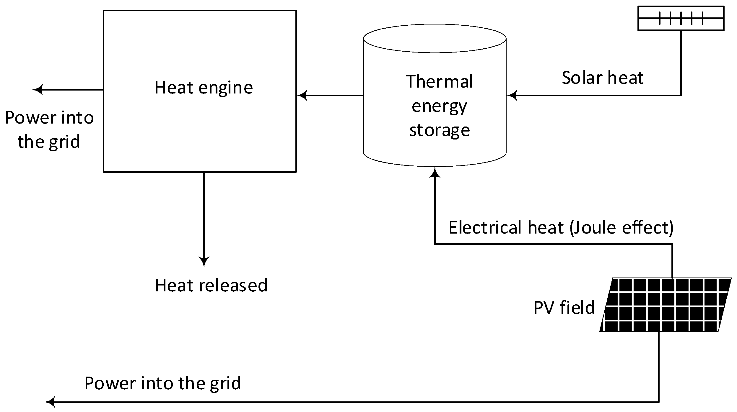
2.1. Concept
2.2. Heat Pump
2.3. Heat Engine
2.4. Solar Field
2.5. Sizing of Heat Exchangers
2.6. Economic Model
3. Results
4. Discussion and Conclusions
Author Contributions
Funding
Institutional Review Board Statement
Informed Consent Statement
Data Availability Statement
Conflicts of Interest
References
- IRENA. Renewable Capacity Statistics 2023; International Renewable Energy Agency: Abu Dhabi, United Arab Emirates, 2023. [Google Scholar]
- Available online: https://www.solarsco2ol.eu/ (accessed on 6 June 2023).
- IEA & NEA. Projected Costs of Generating Electricity, 2020 Edition. Available online: https://www.iea.org/reports/projected-costs-of-generating-electricity-2020 (accessed on 6 June 2023).
- LAZARD, LCOE+, April 2023. Available online: https://www.lazard.com/research-insights/2023-levelized-cost-of-energyplus/ (accessed on 6 June 2023).
- Pilotti, L.; Colombari, M.; Castelli, A.F.; Binotti, M.; Giaconia, A.; Martelli, E. Simultaneous design and operational optimization of hybrid CSP-PV plants. Appl. Energy 2023, 331, 20369. [Google Scholar] [CrossRef]
- Starke, A.R.; Cardemil, J.M.; Escobar, R.A.; Colle, S. Assessing the performance of hybrid CSP + PV plants in northern Chile. Sol. Energy 2016, 138, 88–97. [Google Scholar]
- Pan, C.A.; Dinter, F. Combination of PV and central receiver CSP plants for base load power generation in South Africa. Sol. Energy 2017, 146, 379–388. [Google Scholar] [CrossRef]
- Green, A.; Diep, C.; Dunn, R.; Dent, J. High Capacity Factor CSP-PV Hybrid Systems. Energy Procedia 2015, 69, 2049–2059. [Google Scholar] [CrossRef]
- Starke, A.R.; Cardemil, J.M.; Escobar, R.; Colle, S. Multi-objective optimization of hybrid CSP + PV system using genetic algorithm. Energy 2018, 147, 490–503. [Google Scholar] [CrossRef]
- Parrado, C.; Girard, A.; Simon, F.; Fuentealba, E. 2050 LCOE (Levelized Cost of Energy) projection for a hybrid PV (photovoltaic)-CSP (concentrated solar power) plant in the Atacama Desert, Chile. Energy 2016, 94, 422–430. [Google Scholar] [CrossRef]
- Sumayli, H.; El-Leathy, A.; Danish, S.N.; Al-Ansary, H.; Almutairi, Z.; Al-Suhaibani, Z.; Saleh, N.S.; Saeed, R.S.; Alswaiyd, A.; Djajadiwinata, A.; et al. Integrated CSP-PV hybrid solar power plant for two cities in Saudi Arabia. Case Stud. Therm. Eng. 2023, 44, 102835. [Google Scholar] [CrossRef]
- Stein, W.H.; Buck, R. Advanced power cycles for concentrated solar power. Sol. Energy 2017, 152, 91–105. [Google Scholar] [CrossRef]
- Guccione, S.; Trevisan, S.; Guedez, R.; Laumert, B.; Maccarini, S.; Traverso, A. Techno-Economic Optimization of a Hybrid PV-CSP Plant with Molten Salt Thermal Energy Storage and Supercritical CO2 Brayton Power Cycle. In Proceedings of the ASME Turbo Expo 2022, Rotterdam, The Netherlands, 13–17 June 2022; Volume 4. Cycle Innovations: Energy Storage. [Google Scholar]
- Yang, J.; Yang, Z.; Duan, Y. Load matching and techno-economic analysis of CSP plant with S–CO2 Brayton cycle in CSP-PV-wind hybrid system. Energy 2021, 223, 120016. [Google Scholar] [CrossRef]
- Zurita, A.; Mata-Torres, C.; Valenzuela, C.; Felbol, C.; Cardemil, J.M.; Guzmán, A.M.; Escobar, R.A. Techno-economic evaluation of a hybrid CSP + PV plant integrated with thermal energy storage and a large-scale battery energy storage system for base generation. Sol. Energy 2018, 173, 1262–1277. [Google Scholar] [CrossRef]
- Liu, T.; Yang, J.; Yang, Z.; Duan, Y. Techno-economic feasibility of solar power plants considering PV/CSP with electrical/thermal energy storage system. Energy Convers. Manag. 2022, 255, 115308. [Google Scholar] [CrossRef]
- Cox, J.L.; Hamilton, W.T.; Newman, A.M. Parametric analysis on optimized design of hybrid solar power plants. Sol. Energy 2023, 252, 195–217. [Google Scholar] [CrossRef]
- Bravo, R.; Friedrich, D. Integration of energy storage with hybrid solar power plants. Energy Procedia 2018, 151, 182–186. [Google Scholar] [CrossRef]
- Available online: https://www.solarpaces-conference.org/ (accessed on 6 June 2023).
- Bejan, A. Advanced Engineering Thermodynamics, 2nd ed.; John Wiley & Sons: New York, NY, USA, 1997. [Google Scholar]
- Dostal, V. A Supercritical Carbon Dioxide Cycle for Next Generation Nuclear Reactors. Ph.D. Thesis, Institute of Technology, Cambridge, MA, USA, 2004. [Google Scholar]
- Linares, J.I.; Montes, M.J.; Cantizano, A.; Sánchez, C. A novel supercritical CO2 recompression Brayton power cycle for power tower concentrating solar plants. Appl. Energy 2020, 263, 114644. [Google Scholar] [CrossRef]
- Saranam, V.R.; Paul, B.K. Feasibility of using diffusion bonding for producing hybrid printed circuit heat exchangers for nuclear energy applications. Procedia Manuf. 2018, 26, 560–569. [Google Scholar] [CrossRef]
- Southall, D.; Dewson, S.J. Innovative compact heat exchangers. In Proceedings of the ICAPP ’10, San Diego, CA, USA, 13–17 June 2010. Paper 10300. [Google Scholar]
- Bahamonde-Noriega, J.S. Design Method for S-CO2 Gas Turbine Power Plants. Master’s Thesis, Delft University of Technology, Delft, The Netherlands, 2012. [Google Scholar]
- Mehos, M.; Turchi, C.; Vidal, J.; Wagner, M.; Ho, Z.; Ma, C.; Kolb, W.; Andraka, C.; Kruizenga, A. Concentrating Solar Power Gen3 Demonstration Roadmap, NREL, NREL/TP-5500-67464, 2017. Available online: https://www.nrel.gov/docs/fy17osti/67464.pdf (accessed on 6 June 2023).
- Therminol. 2023. Available online: https://www.therminol.com/heat-transfer-fluids (accessed on 6 June 2023).
- Montes, M.J.; Abánades, A.; Martínez-Val, J.M.; Valdés, M. Solar multiple optimization for a solar-only thermal power plant, using oil as heat transfer fluid in the parabolic trough collectors. Sol. Energy 2009, 83, 2165–2176. [Google Scholar] [CrossRef]
- EuroTrough Project. Final Public Report, European Commission Contract No. JOR3-CT98-00231, Sevilla/Almería/Brussels, 2001. Available online: https://cordis.europa.eu/docs/projects/files/JOR/JOR3980231/51762451-6_en.pdf (accessed on 6 June 2023).
- Serrano, I.P.; Cantizano, A.; Linares, J.I.; Moratilla, B.Y. Modeling and sizing of the heat exchangers of a new supercritical CO2 Brayton power cycle for energy conversion for fusion reactors. Fusion Eng. Des. 2014, 89, 1905–1908. [Google Scholar] [CrossRef]
- Available online: https://www.heatric.com/ (accessed on 6 June 2023).
- Pierres, R.L.; Southall, D.; Osborne, S. Impact of Mechanical Design Issues on Printed Circuit Heat Exchangers. In Proceedings of the 3rd SCO2 Power Cycle Symposium, University of Colorado at Boulder–University Memorial Center, Boulder, CO, USA, 24–25 May 2011. [Google Scholar]
- Li, X.; Smith, T.; Kininmont, D.; Dewson, S. Materials for Nuclear Diffusion-Bonded Compact Heat Exchangers. In Proceedings of the ICAPP’09, Tokyo, Japan, 10–14 May 2009. [Google Scholar]
- Bejan, A.; Tsatsaronis, G.; Moran, M. Thermal Design & Optimization; Wiley: New York, NY, USA, 1996. [Google Scholar]
- Fleming, D.D.; Conboy, T.M.; Pasch, J.J.; Wright, S.A.; Rochau, G.E.; Fuller, R.L. Scaling Considerations for a Multi-Megawatt Class Supercritical CO2 Brayton Cycle and Commercialization, SANDIA REPORT SAND2013-9106, 2013. Available online: https://www.osti.gov/servlets/purl/1111079 (accessed on 6 June 2023).
- Southall, D.; Pierres, R.L.; Dewson, S.J. Design considerations for compact heat exchangers. In Proceedings of the ICAPP ’08, Anaheim, CA, USA, 8–12 June 2008. [Google Scholar]
- Driscoll, M.J.; Hejzlar, P. 300 MWe Supercritical CO2 Plant Layout and Design, MIT Nuclear Engineering Department (2004), MIT-GFR-014. Available online: https://web.mit.edu/22.33/www/dostal.pdf (accessed on 6 June 2023).
- Kurup, P.; Glynn, S.; Akar, S. Manufacturing cost analysis of advanced parabolic trough collector. AIP Conf. Proc. 2022, 2445, 02006. [Google Scholar]
- Linares, J.I.; Martín-Colino, A.; Arenas, E.; Montes, M.J.; Cantizano, A.; Pérez-Domínguez, J.R. Carnot battery based on Brayton supercritical CO2 thermal machines using concentrated solar thermal energy as a low-temperature source. Energies 2023, 16, 3871. [Google Scholar] [CrossRef]
- International Renewable Energy Agency (IRENA). Renewable Power Generation Costs in 2019; International Renewable Energy Agency: Abu Dhabi, United Arab Emirates, 2020; ISBN 978-92-9260-040-2. [Google Scholar]
- Tafur-Escanta, P.; Valencia-Chapi; López-Guillem, M.; Fierros-Peraza, O.; Muñoz-Antón, J. Electrical energy storage using a supercritical CO2 heat pump. Energy Rep. 2022, 8, 502–507. [Google Scholar] [CrossRef]


| Point | Pressure [bar] | Temperature [°C] | Enthalpy [kJ/kg] |
|---|---|---|---|
| 1 | 85.00 | 415.0 | 377.3 |
| 2 | 300.0 | 604.1 | 590.8 |
| 3 | 294.0 | 388.5 | 318.3 |
| 4 | 90.31 | 261.4 | 199.6 |
| 5 | 88.5 | 370.0 | 324.5 |
| 6 | 86.73 | 599.1 | 596.9 |
| Point | Pressure [bar] | Temperature [°C] | Enthalpy [kJ/kg] |
|---|---|---|---|
| 7 | 288.1 | 532.8 | 501.0 |
| 8 | 92.15 | 395.8 | 353.8 |
| 9 | 90.31 | 579.1 | 572.3 |
| 10 | 88.50 | 203.6 | 133.9 |
| 11 | 86.73 | 82.02 | −18.61 |
| 12 | 85.00 | 35.00 | −197.9 |
| 13 | 300.0 | 76.52 | −163.3 |
| 14 | 294.0 | 198.1 | 61.88 |
| 15 | 294.0 | 199.6 | 64.25 |
| 16 | 294.0 | 198.6 | 62.65 |
| Number of loops in the solar field | 78 |
| Number of collectors per loop | 4 |
| Number of modules per collector | 10 |
| Length of every module [m] | 12.27 |
| Absorber tube outer diameter [m] | 0.07 |
| Absorber tube inner diameter [m] | 0.065 |
| Glass envelope outer diameter [m] | 0.115 |
| Glass envelope inner diameter [m] | 0.109 |
| Intercept factor | 0.92 |
| Mirror reflectivity | 0.92 |
| Glass transmissivity | 0.945 |
| Solar absorptivity | 0.94 |
| Peak optical efficiency | 0.75 |
| Mass flow per loop [kg/s] | 7.6 |
| Inlet/outlet HTF temperature [°C] | 300/390 |
| Inlet pressure [bar] | 20 |
| Heat gain per loop [MWth] | 1.6732 |
| Heat loss per loop [kWth] | 158.56 |
| Pressure drop per loop [bar] | 4.1438 |
| Optical efficiency [%] | 71.99 |
| Thermal efficiency [%] | 91.34 |
| Component | Heat Duty or Power [MW] | Mass Flow Rate [kg/s] |
|---|---|---|
| Compressor (HPC) | 219 | 1025 |
| Turbine (HPT) | 122 | 1025 |
| Motor (MOT) | 97 | --- |
| CO2/CO2 (REC) | 279 | 1025/1025 |
| Thermal Oil/CO2 (TOHX) | 128 | 582/1025 |
| CO2/Molten salts (MSHP) | 225 | 1025/798 |
| Component | Heat Duty or Power [MW] | Mass Flow Rate [kg/s] |
|---|---|---|
| Main Compressor (MC) | 12 | 349 |
| Auxiliary Compressor (AC) | 14 | 167 |
| Turbine (HET) | 76 | 516 |
| Generator (GEN) | 50 | --- |
| CO2/CO2 (HTR) | 226 | 516/516 |
| CO2/CO2 (LTR) | 779 | 516/349 |
| Molten salts/CO2 (MSHE) | 113 | 399/516 |
| CO2/Water (PC) | 63 | 349/2995 |
| Component | Heat Duty [MW] | Height [m] | Number of Modules | On-Site Cost [USD M2020] |
|---|---|---|---|---|
| REC | 279 | 3.92 | 96 | 39.0 |
| HTR | 226 | 2.67 | 22 | 21.7 |
| LTR | 79 | 4.25 | 32 | 17.5 |
| PC | 63 | 0.43 | 11 | 11.4 |
| TOHX | 128 | 0.40 | 8 | 10.2 |
| Component | Heat Duty [MW] | Reference PCHE | On-Site Cost [USD M2020] |
|---|---|---|---|
| MSHP | 225 | REC | 30.0 |
| MSHE | 113 | HTR | 10.3 |
| Cycle | On-Site Cost [USD M2020] |
|---|---|
| HP | 50.3 |
| HE | 32.7 |
| Component | Energy Stored [MWh] | Salt Inventory [ton] | Direct Costs [USD M2020] |
|---|---|---|---|
| TES | 1351 | 17,245 | 38.6 |
| PV field | --- | --- | 38.9 |
| PTC Field | --- | --- | 32.5 |
| Component | Base Parameter | Specific Cost (FCI) |
|---|---|---|
| HP [USD2020/kWt] | Heat released (225 MW) | 719.44 |
| HE [USD2020/kWe] | Power produced (50 MW) | 2340 |
| TES [USD2020/kWht] | Thermal energy stored (1351 MWh) | 35.71 |
| PV field [USD2020/kWp] | Peak power (97 MW) | 501.3 |
| PTC field [USD2020/m2] | Solar aperture area (21.7 hm2) | 190.0 |
Disclaimer/Publisher’s Note: The statements, opinions and data contained in all publications are solely those of the individual author(s) and contributor(s) and not of MDPI and/or the editor(s). MDPI and/or the editor(s) disclaim responsibility for any injury to people or property resulting from any ideas, methods, instructions or products referred to in the content. |
© 2023 by the authors. Licensee MDPI, Basel, Switzerland. This article is an open access article distributed under the terms and conditions of the Creative Commons Attribution (CC BY) license (https://creativecommons.org/licenses/by/4.0/).
Share and Cite
Linares, J.I.; Martín-Colino, A.; Arenas, E.; Montes, M.J.; Cantizano, A.; Pérez-Domínguez, J.R. A Novel Hybrid CSP-PV Power Plant Based on Brayton Supercritical CO2 Thermal Machines. Appl. Sci. 2023, 13, 9532. https://doi.org/10.3390/app13179532
Linares JI, Martín-Colino A, Arenas E, Montes MJ, Cantizano A, Pérez-Domínguez JR. A Novel Hybrid CSP-PV Power Plant Based on Brayton Supercritical CO2 Thermal Machines. Applied Sciences. 2023; 13(17):9532. https://doi.org/10.3390/app13179532
Chicago/Turabian StyleLinares, José Ignacio, Arturo Martín-Colino, Eva Arenas, María José Montes, Alexis Cantizano, and José Rubén Pérez-Domínguez. 2023. "A Novel Hybrid CSP-PV Power Plant Based on Brayton Supercritical CO2 Thermal Machines" Applied Sciences 13, no. 17: 9532. https://doi.org/10.3390/app13179532