Article

Research on the Elastoplastic Theory and Evolution Law of Plastic Zone Contours of Horizontal Frozen Walls under Nonuniform Loads

1
Anhui Provincial Key Laboratory of Building Structure and Underground Engineering, Anhui Jianzhu University, Hefei 230601, China
2
College of Civil Engineering, Anhui Jianzhu University, Hefei 230601, China
*
Author to whom correspondence should be addressed.
Appl. Sci. 2023, 13(16), 9398; https://doi.org/10.3390/app13169398
Submission received: 12 April 2023 / Revised: 14 July 2023 / Accepted: 14 August 2023 / Published: 18 August 2023
(This article belongs to the Special Issue Artificial Ground Freezing Technology)

Abstract

:
The study of the changes in stress and deformation of frozen walls during excavation has always been a hot topic in underground freezing engineering, and the size of the plastic zone is an important basis for evaluating the stability of frozen walls. In response to the shortcomings in the current design of horizontal frozen walls, based on the internal excavation unloading conditions of the frozen wall in artificial ground freezing, an elastoplastic mechanical model for the interaction between a circular horizontal freezing wall and unfrozen soil mass is established under nonuniform loads to obtain the corresponding solutions for stress and displacement in the system. In this study, considering the shear stress of the plastic zone, the method for solving the traditional plastic zone contour equation is modified; consequently, the modified solution of the contour equation of the plastic zone for the frozen wall is obtained. Using this theoretical solution, the influence of the external load p 0 and the lateral pressure coefficient λ on the contour line of plastic zone and tensile stress zone are analyzed by combining the project case, the calculation results show that: the λ = 0 . 485 is the critical point where the inner edge of the frozen wall just happens to have tensile stress. When λ < 0 . 485 , the tensile stress zone is inevitable in the inner edge of the frozen wall vertical direction, and its range is only related to λ and increases with the decrease of λ . The p 0 only affects the magnitude of tensile stress in the region, but does not affect its range. At this time, the frozen wall compression plastic zone contour evolves from crescent shaped to ear shaped with the increase of p 0 . When 0 . 485 < λ < 0.61 , there will be no tensile stress zone, the frozen wall compression plastic zone contour also evolves from crescent shaped to ear shaped with the increase of p 0 . When λ > 0.61 , there will be also no tensile stress zone, with the increase of p 0 , the compression plastic zone contour evolves from the crescent shaped in the horizontal direction to the elliptical shaped, and there is no ear-shaped plastic zone in the whole evolution process. Based on our results, we show that our method can be used to provide a theoretical basis for the stability evaluation and parameter (thickness) design calculation of horizontal frozen walls under nonuniform loads.

1. Introduction

Artificial ground freezing [1,2,3,4] is a special construction technology often used in the construction of underground structures in weak, water-bearing strata, such as shaft engineering, tunnel construction, and foundation pit excavation. Research on the stress and deformation of the frozen wall created during the artificial ground freezing process while performing excavations has always been a topic of interest in the field of underground freezing engineering; herein, the size of the plastic zone of the frozen wall is an important measure to evaluate the stability of the frozen wall. It should be noted that, in this paper, plastic zones refer to compression plastic zones. In the literature, in the case of both vertical or horizontal frozen walls, research on their plastic zone radius and stress expression for the case wherein the lateral pressure coefficient λ = 1 —i.e., on the elastic or elastic–plastic characteristics of frozen wall under uniform load—is most common [5,6,7,8,9,10,11]. However, numerous measured data indicate that the in situ stress includes a certain degree of inhomogeneity, i.e., the ratio of horizontal stress to vertical stress (which is referred to as the lateral pressure coefficient λ ) is not equal to 1 [12,13]. This inhomogeneous pressure plays an important role in the failure of underground structures.
Considering this, worldwide, research has been conducted considering nonuniform formation pressure on the surrounding rock of roadways [14,15,16,17,18,19]. Indeed, analytical solutions of models of excavation of circular tunnels in elastic homogeneous materials subject to nonuniform initial stresses (i.e., the solution known as Kirsch’s solution) [20,21] are discussed in textbooks of rock mechanics and excavation analysis due to their importance as basic teaching/learning tools. Nevertheless, the research on the elastoplastic mechanical properties of the frozen wall formed by the artificial ground freezing method under nonuniform load conditions are still lacking and not explicitly developed [22,23]. In particular, under nonuniform load, the initial stress field of the frozen stratum is considerably different from that of the surrounding rock of roadways (as shown in Figure 1 and Figure 2). In particular, as is clear from Figure 2, it is important to consider the interaction between the frozen wall and unfrozen soil in the frozen stratum while studying the mechanical characteristics of the frozen wall before the installation of a lining. However, as shown in Figure 1, before this installation, the surrounding rock of the roadway is just a single medium in the stratum; therefore, the latter case only involves an inhomogeneous stress analysis of a single medium. Therefore, the existing research results of the surrounding rock of roadways under nonuniform load are not suitable for analyzing the mechanical characteristics of horizontal frozen walls.
In the design theory of frozen walls, the vertical frozen wall theory has become relatively mature and has formed a relatively complete set of design theories [24]. However, the design of the horizontal frozen wall is not yet mature, mainly relying on the calculation formula for the vertical frozen wall of the neutral shaft in mining construction and combining the on-site experience method for design [25,26]. In recent years, scholars have focused on the design and research of horizontal frozen walls, which are still in the fields of numerical simulation, model testing, and on-site measurement. They mostly focus on the analysis of temperature and displacement fields [27,28,29,30]. Theoretical analysis only includes partial elastic design research, while elastic–plastic analysis has not yet seen relevant theoretical analysis research [6,22]. However, due to the different ground stresses in the vertical and horizontal directions, the external loads on the horizontal frozen wall are nonuniform, which fundamentally differs from the axisymmetric loads on the vertical frozen wall. Even the optimized design formula for the vertical frozen wall is theoretically not applicable to the horizontal frozen wall [23]. In order to gain a detailed understanding of the deformation and plastic zone contour characteristics of the horizontal frozen wall, and to design the horizontal frozen wall more reasonably, theoretical research on the elastic–plastic design of the horizontal frozen wall urgently needs to be addressed.
Traditionally, while studying the mechanical properties of frozen walls, the considered mechanical model was often assumed to be an infinitely long elastoplastic thick-walled cylinder under confining pressure loading conditions [6,31]. However, because the interaction between the frozen walls and surrounding unfrozen soil, as well as the radial unloading of the frozen wall, were often neglected, this led to an inaccurate analysis of the frozen walls, which consequently led to structural failures. However, in recent years, several scholars have used an unloading model to optimize their study of the mechanical properties of the frozen wall [8,9,10,32,33], which has led to suitable results. Nevertheless, analyses based on the elastoplastic theory for frozen walls using the excavation unloading model and considering the interaction between the frozen wall and unfrozen soil under nonuniform load conditions has not been conducted [34].
Therefore, in this study, considering the unloading effect of excavation, an elastoplastic mechanical model for the interaction between the horizontal frozen wall and surrounding unfrozen soil under nonuniform load conditions is established. In particular, the stress, deformation, and plastic zone contours in the elastic zone of the frozen wall are theoretically analyzed; in this case, the Mohr–Coulomb yield criterion is used as the plastic yielding criterion for the frozen wall. Based on the Mohr–Coulomb yield criterion and considering the shear stress in the plastic zone, the traditional method for calculating the plastic zone of the frozen wall is modified, and thus, a modified analytical solution of the contour equation for the plastic zone of the frozen wall is obtained. Finally, the distribution law of stress and displacement is analyzed for construction wherein the horizontal freezing method is used; based on this analysis, factors influencing the evolution of the elastoplastic zone are studied.

2. Basic Assumptions and Mechanical Models

2.1. Basic Assumptions

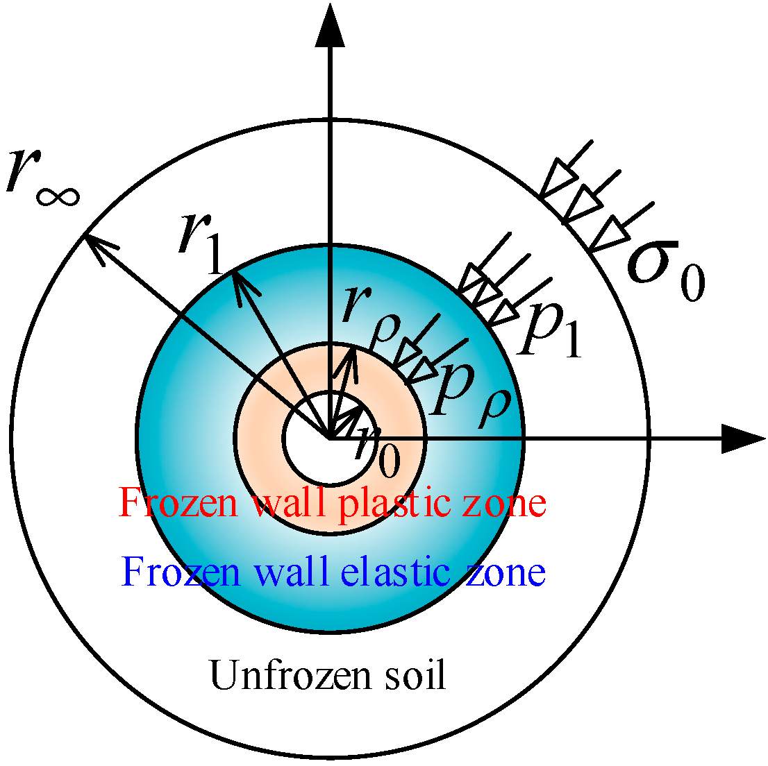
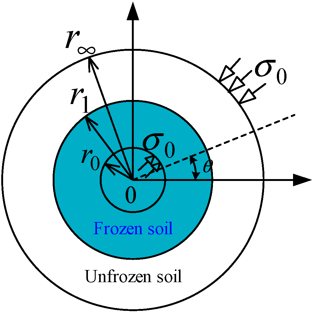
  • The horizontal frozen wall and surrounding unfrozen soil are regarded as infinite thick-walled cylinders; in addition, the plane strain model is used to analyze the mechanical characteristics of the horizontal frozen wall.
  • The frozen wall is homogeneous and composed of ideal elastoplastic material, while the unfrozen soil is also homogeneous, but composed of linear elastic material.
  • The influence of the force of the unfrozen soil and frozen wall’s own weight is ignored in the model under study.
  • All the frozen soil inside the frozen wall is excavated in one instant, and there is no support on the inner edge of the frozen wall after the excavation; i.e., the radial load on the inner edge is 0.
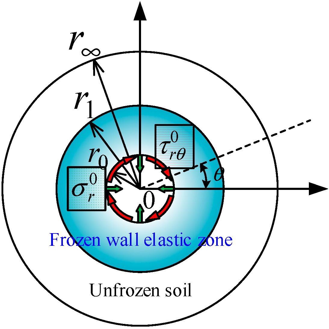
  • There is complete contact between the frozen wall and unfrozen soil; i.e., the radial stress and shear stress on the contact surface are equal; in addition, the radial displacement and circumferential displacement are equal as well.
  • The stress field before and after freezing remains unchanged and is the same as the initial stress field. The initial stress field in the Cartesian coordinate system is expressed as follows:
σ x 0 = λ p 0 , σ y 0 = p 0 , τ x y 0 = 0
Equation (1) can be represented in polar coordinates as follows:
σ r 0 = λ p 0 cos 2 θ + p 0 sin 2 θ = 1 + λ 2 p 0 1 λ 2 p 0 cos 2 θ σ θ 0 = λ p 0 sin 2 θ + p 0 cos 2 θ = 1 + λ 2 p 0 + 1 λ 2 p 0 cos 2 θ τ r θ 0 = ( 1 λ ) p 0 sin θ cos θ = 1 λ 2 p 0 sin 2 θ
where σ 0 represents the initial stress, which is equivalent to the initial stress field given by σ r 0 , σ θ 0 , and τ r θ 0 , with compressive stress being considered positive; p 0 is the initial vertical stress value, p 0 = γ h ; h is the buried depth; γ is the soil weight; and λ is the horizontal lateral pressure coefficient.

2.2. Mechanical Models

The mechanical model considered in our study is shown in Figure 2 and Figure 3. In particular, Figure 2 shows the mechanical model for the initial stress field of the frozen stratum, while Figure 3 shows the mechanical model for the interaction between the frozen wall and surrounding rock after excavation and unloading. Although the contour shape of the elastoplastic zone of the frozen wall does not remain a regular circle under the action of a nonuniform stress field, for stress estimation, each contour can be approximately considered as a circle; then, the exact contour can be determined by solving for elastic stress of the frozen wall.
Based on the abovementioned assumptions, the proposed mechanical model is divided into a frozen wall plastic zone, frozen wall elastic zone, and unfrozen soil elastic zone from the inside to the outside. In Figure 3, the stress boundary of the surrounding unfrozen soil at infinity is the initial stress field σ 0 , load at the interface between the elastic zone of the unfrozen soil and outer surface of the elastic zone of the frozen wall is p 1 , and load at the interface between the inner surface of the elastic zone of the frozen wall and outer surface of the plastic zone of the frozen wall is p ρ .

2.3. Basic Mechanical Equations

The plane strain mechanical model shown in Figure 3 is used to calculate the stress and deformation of the frozen wall under nonuniform loading. The basic equations of elastic mechanics used in solving this model are well known. In particular, the basic mechanical equations in polar coordinates given in the classical literature [14,35] are discussed here.
First, the equilibrium differential equation for the plane strain mechanical model can be expressed as follows:
σ r r + 1 r τ r θ θ + σ r σ θ r = 0 τ r θ r + 1 r σ θ θ + 2 τ r θ r = 0
where σ r and σ θ represent the normal stress components in the radial and hoop directions, respectively, while τ r θ represents the shear stress component.
Second, the geometric equation for the plane strain mechanical model can be expressed as follows:
ε r = u r ε θ = 1 r v θ + u r γ r θ = 1 r u θ + v r v r
where u and v represent the displacement components in the radial and hoop directions, respectively. In addition, ε r and ε θ represent the normal strain components in the radial and hoop directions, respectively, while γ r θ represents the shear strain component.
Third, the physical equation for the plane strain mechanical model can be expressed as follows:
ε r = 1 + ν E 1 ν σ r ν σ θ ε θ = 1 + ν E 1 ν σ θ ν σ r γ r θ = 2 1 + ν E τ r θ
where E and ν are the elastic modulus and Poisson’s ratio of the stratigraphic material, respectively.
The above basic mechanical equations are applicable to both unfrozen soil as well as frozen wall.

3. Frozen Wall Elastic Problem

3.1. Solution of the Elastic Unloading Mechanical Model for the Frozen Wall

The elastic unloading mechanical model problem of the frozen wall can be obtained from the superposition of the equivalent initial stress field before excavation (Figure 4) and virtual excavation disturbance stress field (Figure 5) after the formation of the frozen wall.
Figure 4 shows that the initial stress σ 0 acts on both the inner edge of the frozen wall and outer edge of the unfrozen soil before excavation. In contrast, Figure 5 shows the virtual excavation disturbance stress field after excavation following the formation of the frozen wall, which is equivalent to the unloading force given by σ r 0 and τ r θ 0 at the inner edge of the frozen wall, where σ r 0 is the equivalent radial load and τ r θ 0 is the equivalent shear load. In the unloading model depicted in Figure 5, because the equivalent radial load and equivalent shear load of the inner edge of the frozen wall are trigonometrically related to the polar coordinate angle, it is assumed that the load and angle at the contact surface between the frozen wall and surrounding unfrozen soil are also related trigonometrically.
Depending on the characteristics of the model boundary conditions and plane strain problem, when the semi-inverse solution method is used to solve the abovementioned problems, the plane problem using the stress method can be generalized as solving a stress function that satisfies a compatible equation. Let Φ denote the stress function, then, the compatible equation in polar coordinates is given as follows:
2 r 2 + 1 r r + 1 r 2 2 θ 2 2 Φ r 2 + 1 r Φ r + 1 r 2 2 Φ θ 2 = 0
If the stress function is known, the stress components can be obtained as follows:
σ r = 1 r Φ r + 1 r 2 2 Φ θ 2 σ θ = 2 Φ r 2 τ r θ = 1 r 2 Φ r θ + 1 r 2 Φ θ = r 1 r Φ θ
The stress functions of the unfrozen soil and frozen wall Φ i ( r , θ ) ( i = 1 , 2 ) are represented using separable forms (including f i ( r ) and g i ( r ) con 2 θ ); these stress functions are similar and can be expressed as follows [36,37]:
Φ i r , θ = f i ( r ) + g i r cos 2 θ
Substituting the stress functions of Equation (8) into the compatible Equation (6) yields the following result:
d 4 f i ( r ) d r 4 + 2 r d 3 f i ( r ) d r 3 1 r 2 d 2 f i ( r ) d r 2 + 1 r 3 d f i ( r ) d r + d 4 g i ( r ) d r 4 + 2 r d 3 g i ( r ) d r 3 9 r 2 d 2 g i ( r ) d r 2 + 9 r 3 d g i ( r ) d r cos 2 θ = 0
Equation (9) is applicable to any arbitrary θ . Hence,
d 4 f i ( r ) d r 4 + 2 r d 3 f i ( r ) d r 3 1 r 2 d 2 f i ( r ) d r 2 + 1 r 3 d f i ( r ) d r = 0 d 4 g i ( r ) d r 4 + 2 r d 3 g i ( r ) d r 3 9 r 2 d 2 g i ( r ) d r 2 + 9 r 3 d g i ( r ) d r = 0
It is known that the constant term in the abovementioned stress function has no effect on the stresses and displacements of the unfrozen soil and frozen wall; therefore, we set the constant term in the stress function given by Equation (8) to 0. Hence, by solving the above differential equations, the appropriate stress function expression is obtained as follows:
Φ i ( r , θ ) = a i r 2 + b i r 2 ln r + c i ln r + ( e i + f i r 4 + g i r 2 + d i r 2 ) cos 2 θ
where a i , b i , c i , d i , e i , f i , and g i ( i = 1 , 2 ) are undetermined parameters. When i = 1 , the undetermined parameters in the stress function satisfying the semi-inverse solution of the frozen wall are expressed; in contrast, when i = 2 , the undetermined parameters in the stress function satisfying the semi-inverse solution of the surrounding unfrozen soil are expressed. Substituting Equation (11) into the stress expression of Equation (7), the distribution function of the stress field for the frozen wall and surrounding unfrozen soil can be obtained as follows:
σ r i = ( 2 d i + 4 e i r 2 + 6 g i r 4 ) cos 2 θ + 2 a i + 2 b i ln r + b i + c i r 2 σ θ i = ( 2 d i + 12 f i r 2 + 6 g i r 4 ) cos 2 θ + 2 a i + 2 b i ln r + 3 b i c i r 2 τ r θ i = ( 6 f i r 2 + 2 d i 2 e i r 2 6 g i r 4 ) sin 2 θ
Because the stresses of the surrounding unfrozen soil and frozen wall are solved for in the same manner, we only describe the solution for the stress field of the frozen wall below. The excavation of frozen soil inside the frozen wall can be considered equivalent to a stress relief field acting on the inner edge of the frozen wall, which induces stress redistribution and deformation of the frozen wall. After the excavation of frozen soil inside the frozen wall, the relief stress inside the frozen wall can be expressed as follows:
Δ σ r 1 = σ r 1 σ r 1 0 = 2 d 1 + 4 e 1 r 2 + 6 g 1 r 4 p 0 ( 1 λ ) 2 cos 2 θ + 2 a 1 + 2 b 1 ln r + b 1 + c 1 r 2 p 0 ( 1 + λ ) 2 Δ σ θ 1 = σ θ 1 σ θ 1 0 = 2 d 1 + 12 f 1 r 2 + 6 g 1 r 4 p 0 ( 1 λ ) 2 cos 2 θ + 2 a 1 + 2 b 1 ln r + 3 b 1 c 1 r 2 p 0 ( 1 + λ ) 2 Δ τ r θ 1 = τ r θ 1 τ r θ 1 0 = 6 f 1 r 2 + 2 d 1 2 e 1 r 2 6 g 1 r 4 p 0 ( 1 λ ) 2 sin 2 θ
Furthermore, substituting Equation (13) into the physical as well as geometric equations and simplifying them, the elastic displacement of the frozen wall caused by the relief stress can be obtained as follows:
Δ u 1 = 1 + μ 1 E 1 2 d 1 r 1 1 + μ 1 4 e 1 r 2 g 1 r 3 p 0 ( 1 λ ) r 2 + μ 1 1 + μ 1 4 f 1 r 3 cos 2 θ + 1 μ 1 1 + μ 1 2 a 1 r + 1 μ 1 1 + μ 1 2 b 1 r ln r b 1 r c 1 r 1 μ 1 1 + μ 1 p 0 ( 1 + λ ) r 2 Δ v 1 = 1 + μ 1 E 1 2 d 1 r + 2 f 1 r 3 ( μ 1 + 3 ) 1 + μ 1 + 2 g 1 r 3 1 μ 1 1 + μ 1 2 e 1 r p 0 ( 1 λ ) r 2 sin 2 θ + 4 b 1 r θ E 1

3.2. Determination of Undetermined Parameters

Based on the single value and continuous displacement conditions, we can say that b i = 0 , i.e.,
b 1 = b 2 = 0
According to the Saint-Venant principle, the original rock stress field at a sufficiently far distance will be correspondingly less affected by the excavation and unloading effect inside the frozen wall.
In particular, when r , the stress of the surrounding unfrozen soil after excavation and unloading of the frozen soil at the inner edge of the frozen wall can still be expressed by Equation (2). Comparing Equation (2) with Equation (12), we obtain:
2 d 2 = p 0 ( 1 λ ) / 2 2 a 2 = p 0 ( 1 + λ ) / 2 f 2 = 0
Furthermore, as previously mentioned, because the radial stress and shear stress at the inner edge of the frozen wall are equal to zero after excavation and unloading, the following relationship can be obtained:
( 2 d 1 4 e 1 r 0 2 6 g 1 r 0 4 ) cos 2 θ + 2 a 1 + c 1 r 0 2 = 0 ( 6 f 1 r 0 2 + 2 d 1 2 e 1 r 0 2 6 g 1 r 0 4 ) sin 2 θ = 0
In a similar vein, because the radial stress, shear stress, radial displacement, and circumferential displacement at the contact surface between the frozen wall and surrounding unfrozen soil are equal, we obtain the following:
2 d 1 + 4 e 1 r 1 2 + 6 g 1 r 1 4 = 2 d 2 + 4 e 2 r 1 2 + 6 g 2 r 1 4 2 a 1 + c 1 r 1 2 = 2 a 2 + c 2 r 1 2 6 f 1 r 1 2 + 2 d 1 2 e 1 r 1 2 6 g 1 r 1 4 = 6 f 2 r 1 2 + 2 d 2 2 e 2 r 1 2 6 g 2 r 1 4 1 + μ 1 E 1 2 d 1 r 1 1 1 + μ 1 4 e 1 r 1 2 g 1 r 1 3 p 0 ( 1 λ ) r 1 2 + μ 1 1 + μ 1 4 f 1 r 1 3            = 1 + μ 2 E 2 2 d 2 r 1 1 1 + μ 2 4 e 2 r 1 2 g 2 r 1 3 p 0 ( 1 λ ) r 1 2 + μ 2 1 + μ 2 4 f 2 r 1 3 1 μ 1 E 1 2 a 1 r 1 1 μ 1 E 1 p 0 ( 1 + λ ) r 1 2 1 + μ 1 E 1 c 1 r 1 = 1 μ 2 E 2 2 a 2 r 1 1 μ 2 E 2 p 0 ( 1 + λ ) r 1 2 1 + μ 2 E 2 c 1 r 1 1 + μ 1 E 1 2 d 1 r 1 + 2 f 1 r 1 3 ( μ 1 + 3 ) 1 + μ 1 + 2 g 1 r 1 3 1 μ 1 1 + μ 1 2 e 1 r 1 p 0 ( 1 λ ) r 1 2            = 1 + μ 2 E 2 2 d 2 r 1 + 2 f 2 r 1 3 ( μ 2 + 3 ) 1 + μ 2 + 2 g 2 r 1 3 1 μ 2 1 + μ 2 2 e 2 r 1 p 0 ( 1 λ ) r 1 2
Equations (8)–(11) are simultaneous equations that can be solved using MAPLE, which is a numerical software, to obtain the values of a i , b i , c i , d i , e i , f i , and g i ( i = 1 , 2 ); then, the expressions for stress and displacement in the elastic zone of a horizontal frozen wall can be obtained by substituting the parameter values into Equations (5) and (7). The expressions for stress and displacement of unfrozen soil can be obtained in a similar manner.

4. Frozen Wall Elastic–Plastic Problem

4.1. Preliminary Determination of the Plastic Zone Radius

Yang et al. [9] derived an iterative equation to solve for the radius of the plastic zone of a frozen wall based on different yield criteria and excavation unloading effects in the case when the in situ geostress field is uniform. However, in most cases, the horizontal and vertical stresses are not equal; i.e., λ 1 . Researchers worldwide typically study the plastic zone of surrounding rocks under nonuniform stress field conditions based on the assumption that the surrounding rock after excavation is in an elastic state, subsequently calculating the stress in this elastic state according to the elasticity theory; finally, the stress of the elastic zone is substituted into the plastic yield condition to ascertain whether the surrounding rock has yielded [38]. At this time, the contour shape of the plastic zone of the surrounding rock is no longer a regular circle; instead it has sickle, cross, or other shape [17]. Although this abovementioned method is only an approximation, it is helpful for stress estimation. Furthermore, a similar method can be used for the elastoplastic analysis of a horizontal circular frozen wall under the action of a nonuniform stress field.
In the plane strain state, the relationship between the principal stresses and three polar stress components can be expressed as follows:
σ 1 σ 3 = σ r + σ θ 2 ± σ r σ θ 2 2 + τ r θ 2
The Mohr–Coulomb yield criterion expressed in terms of principal stresses is as follows:
σ 1 = 1 + sin ϕ 1 sin ϕ σ 3 + 2 c cos ϕ 1 sin ϕ = A σ 3 + B
where A = 1 + sin ϕ 1 sin ϕ and B = 2 c cos ϕ 1 sin ϕ .
Substituting Equation (19) into Equation (20), the expression of the yield condition can be obtained as follows:
σ r + σ θ 2 = 1 + A 1 A σ r σ θ 2 2 + τ r θ 2 + B 1 A
Then, substituting Equation (12) into Equation (21), and simplifying it, we obtain
12 f 1 cos 2 θ 2 a 1 B 1 A r p 2 4 e 1 cos 2 θ 2 a 1 B 1 A 1 r p 2 + 36 f 1 2 r 4 + 4 e 1 2 r p 4 24 f 1 e 1 cos 2 2 θ = 1 + A 1 A 2 4 d 1 2 + 36 f 1 2 r p 4 + 24 d 1 f 1 r p 2 + 4 e 1 2 r p 4 + 36 g 1 2 r p 8 + 24 e 1 g 1 r p 6 + c 1 2 r p 4 + 8 d 1 e 1 r p 2 + 24 d 1 g 1 r p 4 + 24 f 1 e 1 + 72 f 1 g 1 r p 2 cos 4 θ 4 d 1 c 1 r p 2 + 12 f 1 c 1 + 4 c 1 e 1 r p 4 + 12 c 1 g 1 r p 6 cos 2 θ 2 a 1 B 1 A 2
Then, Equation (22) can be rewritten in the form of the plastic zone contour equation in the following manner:
f ( r ) = k 1 r p 4 + k 2 r p 2 + k 3 r p 2 + k 4 r p 4 + k 5 r p 6 + k 6 r p 8 + k 7 = 0
where
k 1 = 36 f 1 2 sin 2 2 θ + 4 A 1 + A 2 2 A
k 2 = 24 d 1 f 1 ( 1 + A 1 A ) 2 12 f 1 cos 2 θ ( 2 a 1 B 1 A )
k 3 = ( 8 d 1 e 1 + 72 f 1 g 1 ) ( 1 + A 1 A ) 2 cos 4 θ 4 d 1 c 1 ( 1 + A 1 A ) 2 cos 2 θ + 4 e 1 cos 2 θ ( 2 a 1 B 1 A )
k 4 = ( 4 e 1 2 + 24 d 1 g 1 cos 4 θ 4 c 1 e 1 cos 2 θ + c 1 2 ) ( 1 + A 1 A ) 2 4 e 1 2 cos 2 2 θ
k 5 = ( 24 e 1 g 1 12 c 1 g 1 cos 2 θ ) ( 1 + A 1 A ) 2
k 6 = 36 g 1 2 ( 1 + A 1 A ) 2
k 7 = ( 4 d 1 2 + 24 f 1 e 1 cos 4 θ 12 f 1 c 1 cos 2 θ ) ( 1 + A 1 A ) 2 + 24 f 1 e 1 cos 2 2 θ ( 2 a 1 B 1 A ) 2

4.2. Solution of Plastic Zone Stress

In the plastic zone of the frozen wall, the radial stress σ r p is assumed to be the same as the stress distribution in its elastic zone [38]; in addition, the direction of the principal stress remains unchanged in the plastic and elastic zones. Based on these assumptions and considering Equation (21), the following relationship can be obtained:
t g 2 α = 2 τ r θ σ r σ θ = 2 τ r θ p σ θ p σ r p σ r p + σ θ p 2 = 1 + A 1 A σ r p σ θ p 2 2 + ( τ r θ p ) 2 + B 1 A
where α is the direction of the principal stress of the frozen wall at any angle θ relative to the radius vector orientation of the stress ( σ r p , σ θ p , τ r θ p ) at the calculation point.
As indicated in Figure 6, the stress relationships can be represented in the form of a Mohr’s stress circle; thus, the principal stress direction, radial stress, hoop stress, and shear stress distribution of the plastic zone of the frozen wall can be obtained as follows:
σ r p = ( 2 d 1 + 4 e 1 r 2 + 6 g 1 r 4 ) cos 2 θ + 2 a 1 + 2 b 1 ln r + b 1 + c 1 r 2 σ θ p = ( 1 + A ) ( 1 A ) cos 2 α ( 1 + A ) + ( 1 A ) cos 2 α σ r p + 2 B cos 2 α ( 1 + A ) + ( 1 A ) cos 2 α τ r θ p = ( A 1 ) sin 2 α ( 1 + A ) + ( 1 A ) cos 2 α σ r p + B sin 2 α ( 1 + A ) + ( 1 A ) cos 2 α σ θ p σ r p
where
α = 1 2 arctan 6 f 1 r 6 + 2 d 1 r 4 2 e 1 r 2 6 g 1 sin 2 θ 6 f 1 r 6 + 2 d 1 r 4 + 2 e 1 r 2 + 6 g 1 cos 2 θ c 1 r 2

4.3. Modified Solution for the Plastic Zone Radius

The plastic zone contour equation given by Equation (22) does not consider the redistribution of stress in the plastic zone. In fact, when the frozen wall enters the plastic zone, its stress will be constantly adjusted and redistributed, resulting in continuous expansion of the plastic zone. In order to obtain a more accurate contour equation for the plastic zone than the previous one, a second approximation correction of the contour line of the plastic zone is performed considering stress redistribution of the plastic zone. In particular, for this second approximation, we use the Castner calculation method twice, wherein the initial plastic zone radius is calculated using the Castner method first, and then the stress values σ r p and τ r θ p of the calculated points are obtained using the stress equation of the plastic zone; in this case, the contour line of the plastic zone is assumed to be a circle (the circle is made per the radius of the plastic zone for the calculated point). Finally, a new contour line equation for the plastic zone considering the action of σ r p and τ r θ p is derived in a manner similar to Castner’s method to obtain a more accurate plastic zone radius compared with that of the previous case.
After the approximation correction similar to Castner’s method, the elastic stress field of the frozen wall with σ r p and τ r θ p acting on the inner edge of the frozen wall is obtained as follows:
σ r 1 e = ( 2 d 1 + 4 e 1 r 2 + 6 g 1 r 4 ) cos 2 θ + 2 a 1 + 2 b 1 ln r + b 1 + c 1 r 2 + σ r p r p 2 r 2 σ θ 1 e = ( 2 d 1 + 12 f 1 r 2 + 6 g 1 r 4 ) cos 2 θ + 2 a 1 + 2 b 1 ln r + 3 b 1 c 1 r 2 σ r p r p 2 r 2 τ r θ 1 e = ( 6 f 1 r 2 + 2 d 1 2 e 1 r 2 6 g 1 r 4 ) sin 2 θ + τ r θ p r p 2 r 2
By substituting Equation (26) into Equation (21), the modified implicit equation for the radius of the plastic zone can be obtained as follows:
12 f 1 cos 2 θ 2 a 1 B 1 A r 2 4 e 1 cos 2 θ 2 a 1 B 1 A 1 r 2 + 36 f 1 2 r 4 + 4 e 1 2 r 4 24 f 1 e 1 cos 2 2 θ = 1 + A 1 A 2 4 d 1 2 + 36 f 1 2 r 4 + 24 d 1 f 1 r 2 + 4 e 1 2 r 4 + 36 g 1 2 r 8 + 24 e 1 g 1 r 6 + c 1 r 2 + σ r p r 0 2 r 2 2 + τ r θ p 2 r 0 4 r 4 + 8 d 1 e 1 r 2 + 24 d 1 g 1 r 4 + 24 f 1 e 1 + 72 f 1 g 1 r 2 cos 4 θ 4 d 1 + 3 f 1 r 2 + e 1 r 2 + 3 g 1 r 4 c 1 r 2 + σ r p r 0 2 r 2 cos 2 θ + 12 f 1 τ r θ p r 0 2 + 4 d 1 τ r θ p r 0 2 r 2 4 e 1 τ r θ p r 0 2 r 4 12 g 1 τ r θ p r 0 2 r 6 sin 2 θ 2 a 1 B 1 A 2

5. Engineering Examples and Analysis of the Evolution Law of the Elastoplastic Zone of the Frozen Wall

In the freezing design of the horizontal freezing method, the size of the plastic zone is an important basis for evaluating the stability of the frozen wall. In order to study the evolution law of the elastoplastic zone of the frozen wall under nonuniform load, we taking a horizontal frozen tunnel project as the background; in particular, the effects of the vertical external load p 0 and lateral pressure coefficient λ on the plastic zone contour and range of the tensile stress zone of the horizontal frozen wall are analyzed.
The tunnel is constructed using artificial freezing method, and the designed average temperature of the freezing wall is −10 °C. The buried depth of the tunnel is 187.0~248 m, with a longitudinal slope of i = 1 / 1650 , and the initial pressure of the surrounding soil is between 0.3~0.9 MPa. The rock surrounding the tunnel is composed of N2L2 argillaceous siltstone, sandy mudstone, sandy gravel layer, and N2L2s loose sandstone. The elastic modulus and Poisson’s ratio of frozen soil and unfrozen soil are respectively: E 1 = 150   MPa , μ 1 = 0.35 , E 2 = 20   MPa , μ 2 = 0.35 , and the excavation radius of frozen wall is 3.3 m. The horizontal freezing curtain and freezing hole layout of the tunnel are shown in Figure 7 and Figure 8, respectively, and the relevant geological parameters are listed in Table 1.
Artificial ground freezing is an unstable thermal conductivity problem with complex boundary conditions, and the solution to its freezing temperature field requires consideration of factors such as phase transition, moving boundaries, and internal heat sources. Based on the basic theories of soil moisture migration, heat change, thermodynamics, and poromechanics during freezing, as well as Harlan’s coupled model of water and heat, COMSOL multi-physics finite element software and MATLAB were used to build the numerical calculation models of the freezing temperature field of A–A and B–B sections of the horizontal freezing curtain of the tunnel [2,39,40], as shown in Figure 9. Via finite element calculation and analysis, it was found that the thickness of the frozen wall of the tunnel was 2.76~3.25 m; for the convenience of calculating the thickness of the frozen wall, it is taken as 3 m.

5.1. Safety Analysis of Freezing Engineering

By substituting the relevant engineering and geological parameters into Equations (15)–(18) and solving the simultaneous equations for values of a i , b i , c i , d i , e i , f i , and g i ( i = 1 , 2 ) using MAPLE, we obtain the values listed in the Table 2.
The stress values of the frozen wall under the elastic state can be obtained by substituting the undetermined parameters into Equation (12); the corresponding values for principal stresses, principal stress direction, and yield state for k π / 12 (k = 0, 1, 2, 3, 4, 5, 6) directions are listed in Table 3. Verification using Equation (21) indicates that plastic yield does not occur at the inner edge of the frozen wall of the tunnel; furthermore, the maximum circumferential stress at the inner edge of the frozen wall is 2.76 MPa, which meets the safety factor requirement of the compressive strength being twice the maximum circumferential stress. Under the actual working conditions for the tunnel considered in this study, for a frozen wall thickness of 3 m, it was calculated that, when the vertical external load increases to 1.83 MPa, the frozen wall reaches the elastic limit at the horizontal inner edge, and the vertical external load of the elastic limit is 2.03 times the design load, indicating that the tunnel freezing methodology leads to safe and reliable results.
By substituting the parameters listed in Table 1 and Table 2 in Equations (12) and (14), the stress and displacement distribution of the frozen wall in the No. 7 tunnel using the freezing method construction can be obtained as shown in Figure 10 and Figure 11.
As shown in Figure 10, because the frozen wall is subject to a nonuniform stress field, its radial stress increases at different gradients with the radius in each direction. In particular, when λ < 1 , the radial stress in the horizontal direction increases faster than that in the vertical direction near the inner edge of the frozen wall; in addition, the magnitude of horizontal radial stress is larger than vertical radial stress. In contrast, near the outer edge, the radial stress in the vertical direction increases faster than that in the horizontal direction, and its value is also greater than that in the horizontal direction. However, for r = 5.31 m , the radial stresses in all directions are equal to 0.64 MPa. Furthermore, the circumferential stress in the horizontal direction is significantly greater than that in the vertical direction. Moving along the vector radius from the inner edge to the outer edge, the horizontal circumferential stress decreases, while the vertical circumferential stress remains almost unchanged; in addition, the horizontal circumferential stress at the outer edge of the frozen wall is less than the vertical circumferential stress at the outer edge. As with radial stress distribution, the circumferential stresses in all directions are equal to 1.38 MPa at r = 5 . 81 m . It should be noted that the shear stress is positive for angles in the range of 0–90° and 180–270°, whereas negative for angles in the range of 90–180° and 270–360°; the absolute value of shear stress is strictly symmetrical with respect to the horizontal, vertical, 45°, and 135° directions.
From Figure 11a, it can be seen that the radial displacement distribution of the elastic zone of the frozen wall shows that the vertical radial displacement of the frozen wall is greater than the horizontal radial displacement, and all of these displacements are positive values, i.e., indicating deformation to the excavation face; this can be attributed to the vertical outward load being is greater than the horizontal outward load. Furthermore, moving along a vector radius from the inner edge to outer edge, the radial displacement gradually decreases. From the circumferential displacement distribution shown in Figure 11b, we can see that the circumferential displacement is positive in the direction of 0–90° and 180–270°, negative in the direction of 90–180° and 270–360°, and the absolute value of circumferential displacement is strictly symmetrical with respect to the horizontal, vertical, 45°, and 135° directions.

5.2. Influence of External Load on the Plastic Zone Contour

Figure 12 shows the changes in the shape of the plastic zone contour of the frozen wall with an increase in p 0 for different λ .
If the nonuniformity of the two external loads is strong (as shown in Figure 12a with λ = 0 . 3 ), the tensile stress zone will clearly appear in the vertical direction at the inner edge of the frozen wall. In particular, when the value of p 0 is low, the frozen wall only appears as a crescent-shaped plastic zone within a certain range of the inner edge in the horizontal direction (e.g., contours of 2 MPa and 3 MPa in Figure 12a), and the radius of plastic zone in the direction of 0° and 180° is the largest. As p 0 increases, the plastic zone expands along the horizontal direction towards the outer edge of the freezing wall; in addition, it simultaneously expands along the inner edge of the freezing wall in the vertical direction. The contour of the plastic zone of the frozen wall gradually evolves from the crescent shape under low load to that of an ear-like shape (e.g., the contours of 5 MPa and 12 MPa in Figure 12a), and the plastic zone in the direction of 30–60° (the other three quadrants are similar in terms of the radius of the plastic zone) has the largest radius, which is the weakest position for plastic failure on the frozen wall. Furthermore, the horizontal inner edge of the freezing wall is in the plastic zone, while the outer edge is still in the elastic state; in contrast, for the vertical direction of the frozen wall, the inner edge lies in the tensile stress zone, whereas the outer edge lies in the elastic zone.
If the nonuniformity of the two external loads is neither strong nor weak (as shown in Figure 12c with λ = 0 . 5 ), there is no tensile stress zone in the entire frozen wall. In particular, when the value of p 0 is low, the shape of the plastic zone of the frozen wall is the same as that of λ = 0 . 3 . With an increase in p 0 , the contour of the plastic zone of the frozen wall gradually evolves from a crescent shape to ear-like shape (e.g., contours of 5 MPa and 12 MPa in Figure 12c), and the plastic zone in the direction of 30–60° (the other three quadrants are similar in terms of radius of the plastic zone) has the largest radius, which is the weakest position of plastic failure of the frozen wall, but its evolution process is slower than the case of λ = 0 . 3 . Furthermore, the vertical direction of the frozen wall is entirely in the elastic zone, whereas inner edge and outer edge of the horizontal frozen wall lie in the plastic and elastic zones, respectively.
If the nonuniformity of the two external loads is weak (as shown in Figure 12e with λ = 0 . 8 ), because the stress condition is similar to the stress state under uniform load ( λ = 1 ), the contour of the plastic zone evolves from a crescent shape at the horizontal inner edge to an ellipse with an increase in the external load p 0 on the frozen wall (e.g., contour of 5 MPa in Figure 12e). Thus, in this case, no ear-shaped plastic zone is observed during the entire evolution process, and the radius of plastic zone in the direction of 0° and 180° is always the largest.
Based on our analysis, λ = 0 . 485 is the critical point for which the inner edge of the frozen wall just develops tensile stress under the abovementioned working conditions; this critical point for tensile stress is located on the vertical inner edge of the frozen wall. In contrast, when λ < 0.485 , the tensile stress zone is clearly observed on the inner edge of the vertical direction of the frozen wall, whereas, when λ > 0 . 485 , there is no tensile stress zone on the frozen wall. Furthermore, λ = 0 . 61 is the critical point between the ear-shaped plastic zone and elliptical plastic zone of the frozen wall. Under the effect of high external load and when λ < 0 . 610 , the shape of the plastic zone of the frozen wall is roughly that of an ear, whereas, for λ > 0 . 610 , the shape of the plastic zone is elliptical. Thus, when λ = 0.61 and p 0 = 8 . 95   MPa , the inner edge of the frozen wall in the vertical direction is right at the critical point between the elastic and plastic states.

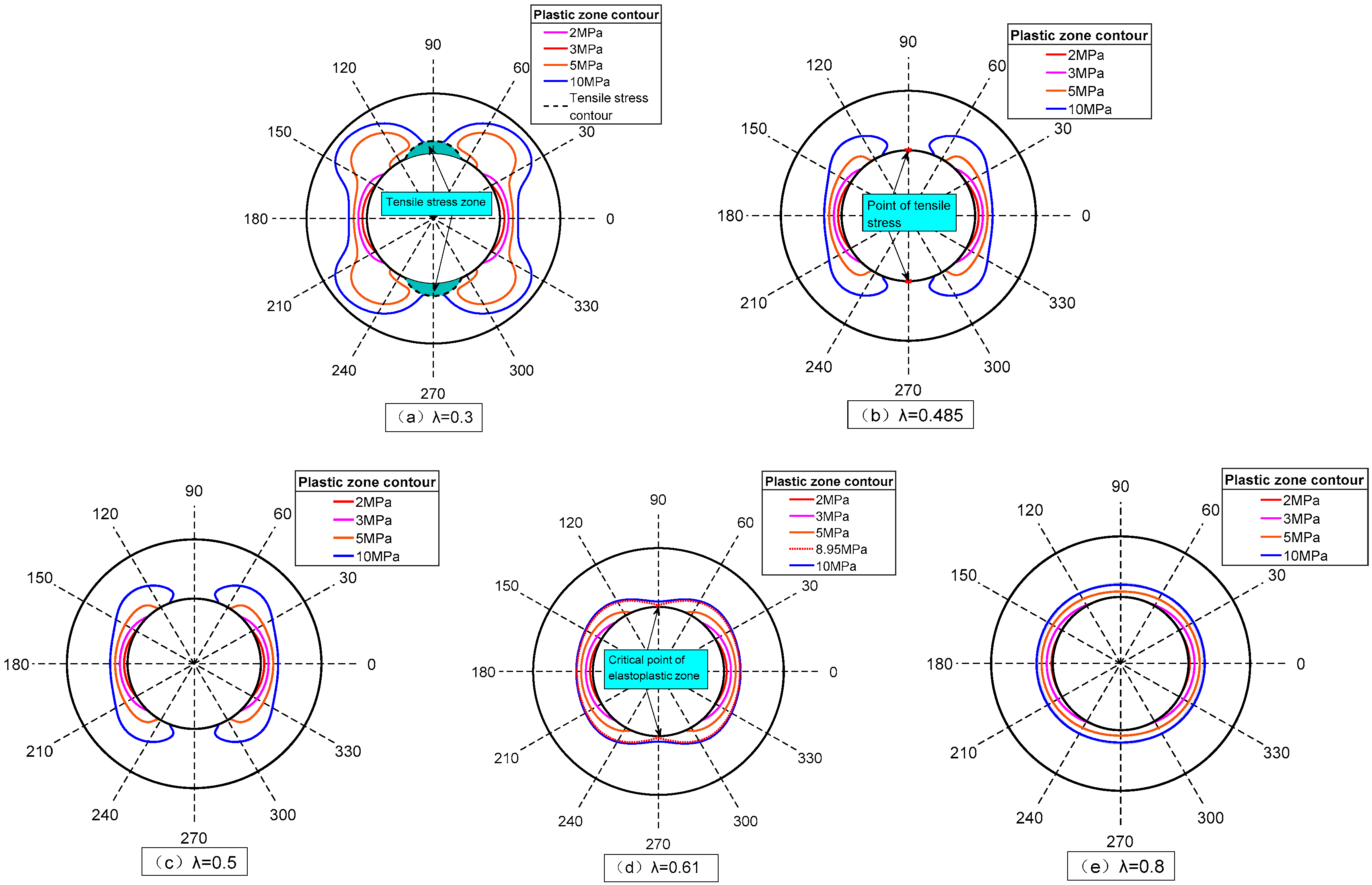
5.3. Influence of the Lateral Pressure Coefficient on the Plastic Zone Contour

The effect of the lateral pressure coefficient λ on the extent and shape of the plastic zone of frozen wall for different cases is shown in Figure 13.
In the case of p 0 = 3   MPa , when the value of λ is low, the contour of the plastic zone of the frozen wall is that of a short, thick crescent shape (e.g., contour of λ = 0 . 3 in Figure 13a), and the range of the horizontal plastic zone is the largest. In contrast, if λ is increased to 1, the crescent-shaped plastic zone gradually expands in the vertical direction along the inner edge of the frozen wall, and the horizontal plastic zone continuously reduces to form a long, thin, crescent-shaped contour, after which this contour becomes elliptical in shape ( λ = 0 . 8 ). When λ > 1 and continues to increase, the horizontal plastic zone decreases gradually, while the vertical plastic zone increases and gradually separates in the horizontal direction, i.e., at 0°, finally forming two crescent shaped plastic zones in the vertical direction.
In the case of p 0 = 5 MPa or 10 MPa, for the same values of λ , the range of the tensile stress zone is the same as that of p 0 = 3 MPa . In particular, when λ = 0.3, the plastic zone contour of the frozen wall is ear-shaped, and the plastic zone in the direction of 30–60° (the other three quadrants are similar in terms of the radius of the plastic zone) has the largest radius, which is the weakest position for plastic failure on the frozen wall. When λ increases to 1, the plastic zone of the frozen wall gradually closes in the vertical direction along the inner edge, and the horizontal plastic zone continuously reduces until an ellipse is formed ( λ = 0.8).

5.4. Discussion on Stability Evaluation of Horizontal Frozen Wall under Uneven Load

Based on the abovementioned analysis of the influence of the lateral pressure coefficient λ and vertical external load p 0 on the plastic zone contour and range of the tensile stress zone of the horizontal frozen wall, the following observations can be made:
(1)
When λ < 0 . 485 , the tensile stress zone is clearly observable at the inner edge of the frozen wall in the vertical direction and its range is only related to λ ; in particular, it increases with a decrease in λ , but is independent of the magnitude of p 0 . Furthermore, p 0 only affects the magnitude of the tensile stress in the stress zone, but does not affect its range. Moreover, a reasonable vertical direction freezing reinforcement should be performed to increase the radius of the frozen wall and avoid tensile failure of the inner edge of the frozen wall.
(2)
When 0 . 485 < λ < 0.610 , there is no tensile stress zone on the frozen wall. In such cases, the plastic failure of the horizontal inner edge under low load and inner edge in the direction 30–60° (the other three quadrants are similar in terms of the radius of the plastic zone) under high load should be avoided.
(3)
When λ > 0.610 , there is no tensile stress zone as in the previous case, and the plastic zone in the 0° and 180° directions has the largest radius, indicating the weakest positions of the plastic wall of the frozen wall. Thus, the compressive plastic failure of the inner edge of the frozen wall in the horizontal direction should be avoided.
For circular horizontal freezing engineering, in practice, λ should first be determined using an in situ stress test to judge whether tensile stress is present in the frozen wall, and the corresponding tensile failure of the tensile stress zone should be determined according to the tensile strength of the frozen soil obtained via the frozen soil mechanics test. By substituting the external load into the plastic contour equation of the frozen wall, the plastic zone can be determined; consequently, the maximum position of the plastic zone can be obtained. Finally, the freezing scheme can be improved based on the determined weak areas.

6. Conclusions

In this study, after deriving the analytical solution of the stress and displacement of the elastic–plastic zone of the frozen wall under nonuniform load, a specific engineering case is analyzed; in particular, the distribution law of stress and displacement of the frozen wall and corresponding influencing factors of the contour of its plastic zone are analyzed. Considering our observations, the following conclusions can be drawn:
The point where λ = 0 . 485 is the critical point at which the inner edge of the frozen wall just develops tensile stress. When λ < 0 . 485 , the tensile stress zone is clearly observed at the inner edge of the frozen wall in the vertical direction, and its range is only related to λ ; in particular, it increases with a decrease in λ . Furthermore, p 0 only affects the magnitude of the tensile stress in the region, but does not affect its range. When λ > 0 . 485 , no tensile stress zone is observed.
When λ < 0.61 , the frozen wall plastic zone contour evolves from a crescent shape to an ear shape as p 0 increases. In contrast, for λ > 0.61 , the plastic zone contour evolves from a crescent shape in the horizontal direction to an elliptical shape with an increase in p 0 , and there is no ear-shaped plastic zone observed during the entire evolution process.
When p 0 = 3   MPa , with an increase in λ tending towards 1, the contour of the plastic zone of the frozen wall evolves from a short, thick crescent shape to long, thin crescent shape until the intersection finally becomes an elliptical plastic zone; in contrast, when p 0 = 5   MPa or 10 MPa, for the same increase in λ , the contour of the plastic zone of the frozen wall gradually closes along the inner edge in the vertical direction evolving from an ear shape to ellipse.
Thus, this study provides a theoretical basis for the design and calculation of stress in horizontal frozen walls under nonuniform load conditions.

Author Contributions

Methodology, S.P.; Validation, Y.X.; Formal analysis, S.P. and G.C.; Resources, L.P.; Writing—original draft, S.P. All authors have read and agreed to the published version of the manuscript.

Funding

The work presented in this paper was financially supported by the National Natural Science Foundation of China (No. 52004003, 51878005, 51874005) and the Natural Science Foundation of Anhui (Grant No. 2208085QE142); The Open Project Program Foundation of Engineering Research Center of underground mine construction, Ministry of Education (No. JYBGCZX2021101, JYBGCZX2020102); Anhui Jianzhu University Teaching Research Project “Research and Application of Modular Teaching Mode for the Course of” Foundation Treatment “from the Perspective of” New Engineering “(2022jy01)”.

Institutional Review Board Statement

Not applicable.

Informed Consent Statement

Not applicable.

Data Availability Statement

The datasets generated and analyzed during the current study are available from the corresponding author upon reasonable request.

Conflicts of Interest

The authors declare no conflict of interest.

References

  1. Andersland, O.B.; Ladanyi, B. An Introduction to Frozen Ground Engineering; Springer Science & Business Media: New York, NY, USA, 2013. [Google Scholar]
  2. Lin, J.; Cheng, H.; Cai, H.B.; Tang, B.; Cao, G.Y. Effect of Seepage Velocity on Formation of Shaft Frozen Wall in Loose Aquifer. Adv. Mater. Sci. Eng. 2018, 2018, 2307157. [Google Scholar] [CrossRef]
  3. Li, K.Q.; Yin, Z.Y.; Liu, Y. Influences of spatial variability of hydrothermal properties on the freezing process in artificial ground freezing technique. Comput. Geotech. 2023, 159, 105448. [Google Scholar] [CrossRef]
  4. Liu, Y.; Li, K.Q.; Li, D.Q.; Tang, X.S.; Gu, S.X. Coupled thermal–hydraulic modeling of artificial ground freezing with uncertainties in pipe inclination and thermal conductivity. Acta Geotech. 2022, 17, 257–274. [Google Scholar] [CrossRef]
  5. Guan, H.D.; Zhou, X.M. Comparing study on elasto-plastic analysis of frozen wall based on interaction between frozen wall and surrounding rock. Rock Soil Mech. 2017, 38, 649–655. [Google Scholar]
  6. Yang, R.S.; Wang, Q.X. Elastic analysis and design of circular horizontal frozen wall based on interaction between frozen wall and surrounding rock. J. China Coal Soc. 2016, 41, 1069–1077. [Google Scholar]
  7. Cui, G.X. Mechanical analysis on cylindrical frozen soil wall and mine shaft lining in deep overburden. Coal Sci. Technol. 2008, 36, 17–21. [Google Scholar]
  8. Yang, W.H.; Yang, Z.J.; Han, T.; Zhang, C.; Bo, D.-L. Elastic design theory of frozen soil wall based on interaction between frozen soil wall and surrounding rock. Chin. J. Geotech. Eng. 2012, 34, 516–520. [Google Scholar]
  9. Yang, W.H.; Yang, Z.J.; Bo, D.L. Elastic-plastic design theory of frozen soil wall based on interaction between frozen soil wall and surrounding rock. Chin. J. Geotech. Eng. 2013, 35, 175–180. [Google Scholar]
  10. Yang, W.H.; Du, Z.B.; Yang, Z.J.; Bo, D.-L. Plastic design theory of frozen soil wall based on interaction between frozen soil wall and surrounding rock. Chin. J. Geotech. Eng. 2013, 35, 1857–1862. [Google Scholar]
  11. Li, K.Q.; Li, D.Q.; Liu, Y. Meso-scale investigations on the effective thermal conductivity of multi-phase materials using the finite element method. Int. J. Heat Mass Transf. 2020, 151, 119383. [Google Scholar] [CrossRef]
  12. Amadei, B.; Stephansson, O. Methods of In Situ, Stress Measurement, Rock Stress and Its Measurement; Springer: Dordrecht, The Netherlands, 1997. [Google Scholar]
  13. Ni, X.H. In-Situ Stress Study and Applications; China Coal Industry Publishing House: Beijing, China, 2007. [Google Scholar]
  14. Jaeger, J.C.; Cook, N.G.W.; Zimmerman, R.W. Fundamentals of Rock Mechanics, 4th ed.; Blackwell Publishing Ltd.: Oxford, UK, 2007. [Google Scholar]
  15. Hudson, J.A.; Harrison, J.P. Engineering Rock Mechanics. An Introduction to the Principles, 1st ed.; Elsevier Science, Ltd.: Oxford, UK, 2000. [Google Scholar]
  16. Sun, J.S.; Lu, W.B. Analytical elasto-plastic solutions to supporting rock masses of circular tunnels under asymmetric load. Rock Soil Mech. 2007, 28, 327–332. [Google Scholar]
  17. Chen, L.W.; Peng, J.B.; Fan, W.; Sun, P. Analysis of surrounding rock mass plastic zone of round tunnel under non-uniform stress field based on the unified strength theory. J. China Coal Soc. 2007, 32, 20–23. [Google Scholar]
  18. Pan, Y.; Zhao, G.M.; Meng, X.R. Elasto-plastic analysis on surrounding rock mass under non-uniform stress field. J. China Coal Soc. 2011, 36, 53–57. [Google Scholar]
  19. Gao, Z.N.; Meng, X.R.; Wang, G.D. Analysis of the plastic zone of surrounding rock under seepage and a non-axisymmetric load. Mod. Tunn. Technol. 2014, 51, 70–75. [Google Scholar]
  20. Kirsch, G. Die Theorie der Elastizität und die Bedürfnisse der Festigkeitslehre. Z. Ver. Dtsch. Ing. 1898, 42, 797–807. [Google Scholar]
  21. Pariseau, W.G. Design Analysis in Rock Mechanics; Taylor & Francis: Abingdon, UK, 2007. [Google Scholar]
  22. Wang, Y.; Yang, W.H. Elastic design theory of circular horizontal frozen wall. J. China Coal Soc. 2015, 40, 2049–2056. [Google Scholar]
  23. Simanjuntak, T.; Marence, M.; Mynett, A.E.; Schleiss, A.J. Pressure tunnels in non-uniform in situ stress conditions. Tunn. Undergr. Space Technol. 2014, 42, 227–236. [Google Scholar] [CrossRef]
  24. Cui, G.; Yang, W.; Lü, H. Frozen Wall and Shaft Lining in Deep Alluvium; China University of Mining and Technology Press: Xuzhou, China, 1998. [Google Scholar]
  25. Chen, Z.; Zhang, B. Calculation method for inclined shaftfrozen wall. Mine Constr. Technol. 2013, 34, 39–42. [Google Scholar]
  26. Yanan, C. A Numerical Analysis of the Ice-Wall Thickness and Freezing Period for Guangzhou Metro Tunnel. Master’s Thesis, Beijing Jiaotong University, Beijing, China, 2008. [Google Scholar]
  27. Zhou, X.; Wang, M.; Tao, L.; Yang, S. Model test and prototype observation on artificial ground freezing and tunneling of Beijing subway. Chin. J. Geotech. Eng. 2003, 25, 676–679. [Google Scholar]
  28. Geng, P.; Yan, Q.; He, C.; Bo, W. Numerical simulation of underground construction by horizontal ground freezing method. Eng. Mech. 2010, 27, 122–127. [Google Scholar]
  29. Wu, Y.; Li, D.; Yang, M. Numerical simulation of tunnel with freezing method construction. Chin. J. Rock Mech. Eng. 2005, 24 (Suppl. S2), 5851–5856. [Google Scholar]
  30. Zhou, X.; Zheng, Y. Research on displacement field of tunnel freezing in high water clay based on simulation model test. J. Tongji Univ. (Nat. Sci.) 2000, 28, 472–476. [Google Scholar]
  31. Zhou, T.J.; Zhou, G.Q. Calculation method of frozen soil wall thickness for inclined shaft in consideration of the shaft inclination. J. China Univ. Min. Technol. 2016, 45, 514–520. [Google Scholar]
  32. Hu, X.D. A mechanical model of interaction of frozen soil wall and surrounding earth mass in unload state. J. China Coal Soc. 2001, 26, 507–511. [Google Scholar]
  33. Hu, X.D. Determination of load on frozen soil wall in unload state. J. Tongji Univ. 2002, 30, 6–10. [Google Scholar]
  34. Zhang, W.; Wang, B.S.; Wang, Y. Elastic Analysis of Nonhomogeneous Frozen Wall under Nonaxisymmetric Ground Stress Field and in State of Unloading. Adv. Mater. Sci. Eng. 2018, 2018, 2391431. [Google Scholar] [CrossRef]
  35. Muskhelishvili, N.I. Some Basic Problems of the Mathematical Theory of Elasticity; P. Noordhoff Ltd.: Groningen, The Netherlands, 1953. [Google Scholar]
  36. Lu, A.Z.; Zhang, N.; Xu, Y.Q.; Cui, P. Stress-displacement solution for a lined vertical borehole due to non-axisymmetric in situ stresses. Int. J. Rock Mech. Min. Sci. 2013, 57, 64–74. [Google Scholar] [CrossRef]
  37. Carranza-Torres, C.; Rysdahl, B.; Kasim, M. On the elastic analysis of a circular lined tunnel considering the delayed installation of the support. Int. J. Rock Mech. Min. Sci. 2013, 61, 57–85. [Google Scholar] [CrossRef]
  38. Yu, X.F.; Zheng, Y.R.; Liu, H.H.; Fang, Z.C. Stability Analysis of Surrounding Rock of Underground Engineering; China Coal Industry Publishing House: Beijing, China, 1983. [Google Scholar]
  39. Cheng, H.; Lin, J.; Wang, B.; Rong, C.X. Mathematical model and test verification of seepage freezing in saturated sand layer. Sci. Technol. Eng. 2018, 18, 38–44. [Google Scholar]
  40. Wang, B.; Rong, C.; Cheng, H.; Cai, H.; Dong, Y.; Yang, F. Temporal and spatial evolution of temperature field of single freezing pipe in large velocity infiltration configuration. Cold Reg. Sci. Technol. 2020, 175, 103080. [Google Scholar] [CrossRef]
Figure 1. Initial stress field of the surrounding rock of the roadway.
Applsci 13 09398 g001
Figure 2. Initial stress field of the frozen stratum.
Applsci 13 09398 g002
Figure 3. Mechanical model of the interaction between the frozen wall and surrounding rock after excavation and unloading.
Applsci 13 09398 g003
Figure 4. Equivalent initial stress field of the frozen wall before excavation.
Applsci 13 09398 g004
Figure 5. Virtual excavation disturbance stress field after the formation of the frozen wall.
Applsci 13 09398 g005
Figure 6. τ σ curve of Mohr’s stress circle.
Applsci 13 09398 g006
Figure 7. Schematic layout of the freezing pipes.
Applsci 13 09398 g007
Figure 8. Profile chart of the freezing holes.
Applsci 13 09398 g008
Figure 9. Grid division and frozen temperature field distribution cloud map.
Applsci 13 09398 g009
Figure 10. Stress distribution for the frozen wall in the No. 7 Tunnel construction using the freezing method.
Applsci 13 09398 g010
Figure 11. Displacement distribution of the frozen wall.
Applsci 13 09398 g011
Figure 12. Relationship between the external load and plastic zone contour of the frozen wall.
Applsci 13 09398 g012
Figure 13. Relationship between the lateral pressure coefficient and plastic zone contour of the frozen wall.
Applsci 13 09398 g013
Table 1. Physical and mechanical parameters of the frozen wall and unfrozen soil mass.
Parameters
Material Types
Frozen WallUnfrozen Soil
Elastic modulus/MPa15020
Poisson ratio0.350.35
Lateral pressure coefficient0.80.8
Compressive strength/MPa5.580.99
Cohesive strength/MPa1.450.28
Internal friction angle/°3530
Bulk density/kN·m319.222.0
Table 2. Stress function parameters.
ParametersValueParametersValue
a 1 0.52 a 2 0.41
b 1 0.00 b 2 0.00
c 1 −11.36 c 2 −2.11
d 1 0.106 d 2 0.045
e 1 −2.06 e 2 −0.39
f 1 −6.60 × 10⁻⁴ f 2 0.00
g 1 10.80 g 2 −1.72
Table 3. Stress and elastic–plastic state of the inner edge of the frozen wall.
Angle
θ
First Principal Stress
σ 1 /MPa
Second Principal Stress
σ 2 /MPa
Principal Stress Direction
α + θ
Yield State
2.760Not yielding
15°2.67015°Not yielding
30°2.42030°Not yielding
45°2.09045°Not yielding
60°1.75060°Not yielding
75°1.51075°Not yielding
90°1.42090°Not yielding
Disclaimer/Publisher’s Note: The statements, opinions and data contained in all publications are solely those of the individual author(s) and contributor(s) and not of MDPI and/or the editor(s). MDPI and/or the editor(s) disclaim responsibility for any injury to people or property resulting from any ideas, methods, instructions or products referred to in the content.

