Article

Improving the Measurement of Characteristic Parameters for the Determination of GHG Emissions in the Semiconductor and Display Industries in Korea

Korea Testing and Research Institute (KTR), 98 Gyoyukwon-ro, Gwacheon-si 13810, Gyeonggi-do, Republic of Korea
*
Author to whom correspondence should be addressed.
Appl. Sci. 2023, 13(15), 8834; https://doi.org/10.3390/app13158834
Submission received: 14 April 2023 / Revised: 10 June 2023 / Accepted: 19 July 2023 / Published: 31 July 2023

Abstract

:
Semiconductor and display industries in the Republic of Korea make up the global electronics market with some of the greatest potential for growth due to accelerated digital transformation. Greenhouse gases (GHGs) present in the Earth’s atmosphere could trap heat and contribute to the greenhouse effect, leading to global warming and climate change, and it is important to note that while GHGs are naturally present in the atmosphere and play a crucial role in regulating the Earth’s temperature, human activities have significantly increased their concentration, leading to accelerated global warming and climate change. Volatile fluorinated compounds (FCs), including perfluorocompounds (PFCs), hydrofluorocompounds (HFCs), NF3, and SF6, are potent long-standing greenhouse gases that are used and emitted by electronics during the manufacturing and display stages of semiconductors. In accordance with global climate change, GHG reduction has developed as a demand of the times, and the electronics industry has also made efforts to reduce GHG emissions in response. Until now, process emissions from the use of fluorinated greenhouse gases (F-GHGs) in various industries have been calculated according to the ’06 IPCC G/L, and emission factors of ’06 IPCC G/L have also been applied. However, the reduction and emission factors proposed in the IPCC G/L are values that do not reflect the latest and advanced reduction technologies in South Korean electronics, and national GHG emissions are overestimated. In this paper, by preparing accurate measurement methods for destruction removal efficiency (DRE), the use rate of gas (Ui), and b-product emission factors (Bby-product, i), which are characteristic parameters for estimating GHG Tier 3a emissions, we aim to increase the accuracy of GHG emissions by advancing emission factors that are unique to the semiconductor and display industries within the Republic of Korea.

1. Introduction

Semiconductor and display industries in the Republic of Korea are continuously increasing greenhouse gas (GHG) emissions due to the rapid growth in production volume [1,2,3,4,5,6,7]. In total, 60–70% of GHG emissions from the semiconductor and display industries are indirect emissions released through electricity consumption, but they are still unlikely to contribute to GHG reductions for carbon neutrality by improving process efficiency [7,8].
There is a lack of related studies for GHG assessment in Korea. With these issues, various industries used the default emission factor presented in the Intergovernmental Panel on Climate Change (IPCC) guidelines for national GHG inventories to date. The IPCC has recently recommended applying country-specific reduction and emission factors rather than default values [9]. When country-specific emission factors for each industry that have recently been studied are developed and compared with the previously applied IPCC default values, results showing significant differences have been confirmed. By comparing these results, we found that domestic semiconductor and display industries overestimate GHG emissions using IPCC default factors. Therefore, recognizing the fact that GHG emission calculations have been overestimated, various studies are being conducted to develop country-specific reduction and emission factors [9,10,11,12,13]. Through these efforts, determining appropriate GHG emission factors that are suitable for the nation’s conditions will be essential for domestic GHG forecasting and reduction strategy establishment. Currently, process emissions from fluorinated gases in the domestic semiconductor and display industries are calculated based on the ’06 IPCC guidelines, and applied emission factors are also based on ’06 IPCC default values [14,15]. However, reduction and emission factors presented in the IPCC guidelines have been quite conservative and have not reflected the latest advanced abatement technologies in the domestic semiconductor and display industries. As a result, GHG emissions from domestic semiconductor and display facilities and national GHG emissions are being overestimated. Accordingly, developing site-specific emission factors at the workplace level by directly measuring GHG emission calculation characteristic parameters is necessary; thus, reducing GHG emissions and carbon neutrality may be realized. Nevertheless, there is currently insufficient research on directly estimating the characteristic parameters of GHG emission calculation, but through measurement research on the characteristic parameters of GHG emission calculation, we proposed clear measurement methods for securing the reliability of GHG emissions over facilities in the semiconductor and display sectors, as well as destruction removal efficiency (DRE), the use rate of gas (Ui), and by-product emission factor (Bby-product, i).
The most recently published ’19 IPCC refinement G/L presented Tier 1, 2, and 3 methods for estimating GHG emissions in electronics manufacturing, and this paper included Tier 2 and 3 methods, which are the most generalized methods. This paper also focused on the Tier 3a method, which is a direct self-measurement method based on facilities. The classification and difference values according to the Tiers 1, 2, and 3 were tabulated, as shown in Table S1. The Tier 2 method could be applied when activity data on the process gas were used by each company, divided into Tiers 2a, 2b, and 2c. Among them, the Tier 2a method showed methodology application only to the semiconductor sub-sector using the default emission factors presented in the ’19 IPCC refinement G/L, regardless of process and wafer size. The use rate of gas (Ui) and emission factor for by-products generated from input gas (Bk, i) were used in the Tier 2a emission calculation formula, indicating the average value of the process for each wafer size [15]. Compared to the Tier 2a method, the Tier 2b method showed the same formula but, dissimilarly, it considered the wafer size of 200 mm or less or 300 mm size. As a result, the method used for estimating GHG emissions based on wafer size is the most noticeable change in the semiconductor and display sectors of the ’19 IPCC Refinement guidelines. The Tier 2c method was used for the sub-sector calculation of electronics, and both emission factors (Ui, p and Bk, i, p) were provided as (p) for each type of process [15,16]. The semiconductor process types were divided into six types: etching and wafer cleaning (EWC), remote plasma cleaning (RPC), in situ plasma cleaning (IPC), in situ thermal cleaning (ITC), N2O TFD, and N2O ‘Other’, etc., and display process types could be classified into four types: etching, remote plasma cleaning (RPC), in situ plasma cleaning (IPC), and N2O TFD [17]. In the case of the semiconductor process, the emission was obtained for each wafer size, but in the case of the display, the wafer size was separately ignored. When the default emission factors were not applicable, a (1-Ui) value of 0.8 was used, and the by-product factor value applied 0.15 for CF4 and 0.05 for C2F6 [18].
In the case of the Tier 3a methodology, which is the focus of this study, the same calculation formula as Tier 2c was applied, but all coefficients (Ui, p, Dk, p, and Bk, I, p) required for calculation used values that were estimated by measuring each manufacturing process. Since the coefficient was calculated through direct measurement, it was also possible to estimate the emissions of the manufacturing process, equipped with a wafer size of 450 mm, and research on accurate measurement methods for the use rate of gas (Ui), destruction removal efficiency (DRE), and by-product emission factor (Bby-product, i) was essential in order to accurately estimate GHG emissions. Furthermore, the Tier 3b method was added to Tier 3b to calculate emissions using the stack system, which measures the GHGs emitted by each process at the end-of-pipe (stack) process. Since this methodology also estimated GHG emissions by adopting the direct measurement method, it was also possible to measure emissions on the 450 mm wafer size and calculate GHG emissions by applying more variables [15].
In this paper, by offering accurate measurement methods for the destruction removal efficiency (DRE), use rate of gas (Ui), and by-product emission factor (Bby-product, i), which are characteristic parameters for calculating GHG emissions of the Tier 3a method, we aimed to increase the accuracy of GHG emissions by improving emission factors that are unique to the semiconductor and display industries of the Republic of Korea.

2. Materials and Methods

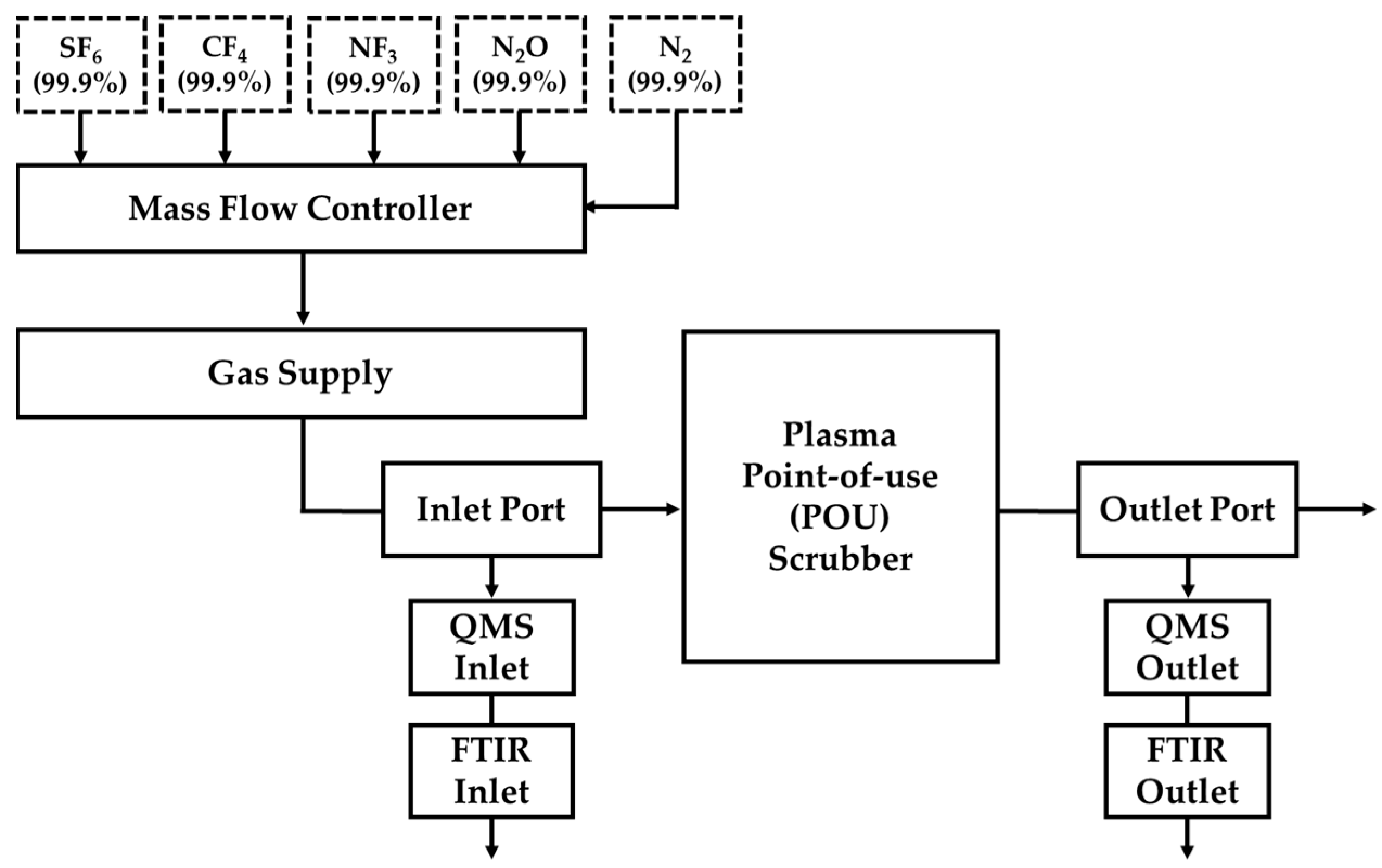
2.1. Measurement Methods and Conditions of the DRE, Use Rate of Gas (Ui), and By-Product Emission Factor (Bby-product, i)

DRE, the use rate of gas (Ui), and by-product emission factor (Bby-product, i) were calculated on site using the semiconductor and display manufacturing facilities during normal operation. Based on the on-site circumstances and process gas being used, the volume flowrate of the gas entering and gas emitting processes from the abatement equipment was measured using a quadrupole mass spectrometer (QMS), and the concentration of the targeted FCs or N2O was measured using a Fourier transform infrared spectrometer (FT-IR) (Figure 1).
The QMS and FT-IR equipment regulations used for measurement purposes are specified in SEMATECH [16], and measurements were performed using the equipment that complies with them. QMS is a mass spectrometer, mainly used for gas analysis, that uses an ion separation quadrupole. In this study, it was used for the purpose of calculating the flow rate of process exhaust gas by measuring the concentration of the injected tracer gas and calculating the dilution ratio, and a mass analyzer with a minimum specification of 0 to 100 amu should be used to include both the composition of the exhaust gas and the mass range of the tracer gas. Additionally, in order to maintain the vacuum pressure, a vacuum pump and pressure gauge were installed and used together. FT-IR is a device that enables qualitative and quantitative analysis by measuring the number of infrared rays absorbed by a sample, and it is used for the purpose of measuring the concentration of the target substance contained in the exhaust gas from the process. The gas cell installed in the FT-IR uses standardized cells and vacuum-only fittings, and is accurately placed on the holder by attaching the window made of KBr, ZnSe, or Ge/ZnSe material through which infrared light passes. The gas cell that is suitable for the type and concentration of the target gas should be applied, as well as the length for each type of scrubber, as mentioned in Table S3.
This measurement guidelines used for estimating the DRE, use rate of gas (Ui), and by-product emission factor (Bby-product, i) apply nitrous oxide (N2O), hydrofluorocarbon (HFC), perfluorocarbon (PFC), sulfur hexafluoride (SF6), and nitrogen trifluoride (NF3), among other semiconductors and display manufacturing process emissions as target substances in order to calculate the GHG emissions presented in the guidelines for reporting and certifying the trading of GHG emissions. Hydrofluorocarbons (such as HFC-23 (CHF3) and HFC-32 (CH2F2)) and perfluorocarbons (such as PFC-14 (CF4), PFC-116 (C2F6), PFC-218 (C3F8), and PFC-c318 (c-C4F8)) were used in this measurement method, and the detection limit (DL) for each gas cell of FT-IR was in accordance with Table S2.
Interfering substances that were found to affect the measurement’s results in the process included moisture found via spectrum interference. In order to eliminate this interference, the gas sample must be heated to 100 °C or more before the gas sample flows into the analysis device to minimize the inflow of moisture and substances, causing interference. Due to overlapping with the reference spectrum region of the target gas, measurements should be reset to a spectrum that does not overlap in order to minimize interference.
The tracer gas injected into the pipeline to calculate the flow rate of the process exhaust gas was chemically stable and was also well mixed and diffused with the atmosphere, and the tracer gas that was applied used helium (He), neon (Ne), argon (Ar), krypton (Kr), and xenon (Xe) gases, which are inert gases used for measuring the volume flow rate of GHG emissions from the manufacturing process. The injecting position of the tracer gas was at the rear end of the pump in the manufacturing process and the distance between the inlet of the tracer gas and the inlet of the scrubber should be installed at least 1 m (POU scrubber) or 5 m (house scrubber) so that the tracer gas could be sufficiently mixed. Before measurements were taken, the whole part of the measuring instrument should be inspected. In particular, it is necessary to check whether gas leaked, and the power should be turned on according to the order, and the sample’s standby flow rate and other conditions should be adjusted according to the manual. Then, when the steady state was reached, QMS and FT-IR instruments should be used to calibrate for accurate measurements. Finally, on-site manufacturing was facilitated during normal operation, and QMS and FT-IR operate to continuously estimate the volume flow rate, and concentration of the target gas for 1 h in order to calculate the DRE, use rate of gas (Ui), and by-product emission factors (Bby-product, i). These measurements were calculated at each scrubber point in semiconductor and display facilities.

2.2. Destruction Removal Efficiency (DRE)

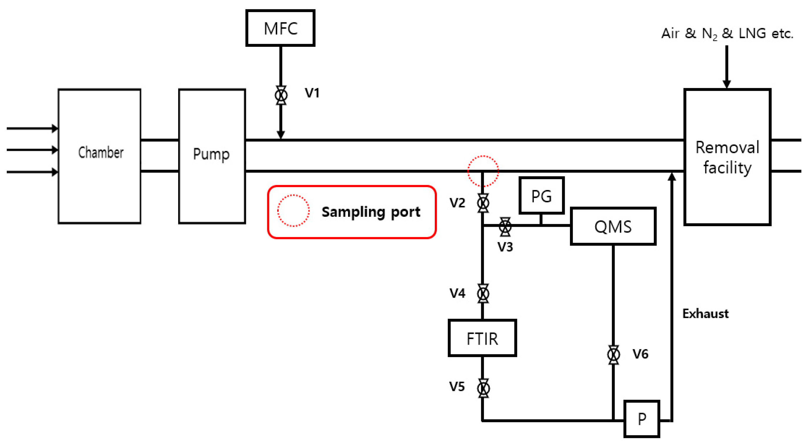
2.2.1. Characteristic Parameter Features

Destruction removal efficiency (DRE) refers to the ratio of the destroyed or reduced greenhouse gas emitted from the manufacturing process by the GHG abatement equipment, such as the point-of-use (POU) scrubber or house scrubber, which is located at the rear of the semiconductor, and the display manufacturing process chamber, revealing a significant difference in the GHG emissions depending on the DRE factor, which makes DRE the most critical factor in determining the GHG emissions in the semiconductor and display industries.
According to the 2019 IPCC Refinement, the DRE of fluorinated compound (FC) gas is 0.89~0.99 and the DRE of N2O gas is 0.6 (Table 1).
As it is the most critical factor in determining GHG emissions, various studies have been conducted, including SEMATECH, ISMI, UN EPA, KTR, etc., and a DRE measurement method using Fourier transform infrared spectroscopy (FT-IR) and quadruple mass spectrometry (QMS) have been established using an EPA protocol in USA and Korea Standard (KS) in the Republic of Korea [16,17,18,19,20,21,22,23,24,25].

2.2.2. Calculation of Destruction Removal Efficiency (DRE)

The average volume flow rate of the exhaust gas from the process can be calculated from the measured concentration of the tracer gas using the QMS based on Equation (1).
F = S f C K r × 10 6
  • F: the average volume flow rate of exhaust gas from the process based on a single concentration data points (L/min);
  • Sf: the volume flow rate of tracer gas injected using a MFC (L/min);
  • CKr: the measured concentration of tracer gas using the QMS (μmol/mol).
The average volume flow rate is calculated using Equations (2) and (3);
F m = 1 n F i n  
σ F m = 1 n 1 n ( F i F m ) 2  
  • Fm: the average volume flow rate of tracer gas from 1~n times measurements (L/min);
  • Fi: the measured volume flow rate of process emission gas from i time measurements (L/min);
  • n: number of measurements;
  • σFm: relative errors.
The volume flow rate of FCs can be determined based on the concentration of GHGs that are measured with FT-IR (Equation (4)).
V i = i = 1 N F m , i C i , j = F m , i i = 1 N C i , j
  • Vi: the volume flow rate of FC gas i (L/min);
  • Fm: the average volume flow rate of tracer gas from 1~n times the number of measurements (L/min);
  • Ci: the concentration of FC gas i (μmol/mol);
  • Ci,j: the concentration of FC gas i, j entering, or being emitted from, the abatement equipment (μmol/mol);
  • j: the concentration of gas entering, or being emitted from, the abatement equipment.
Using the volume flow rate of the entering and emitting FCs from Equation (4), the DRE is determined using Equation (5).
DRE = ( 1 V i , o u t V i ,   i n ) × 100 ( % )
  • Vi,in: the volume flow rate of FC gas i that flows into the abatement equipment per unit time under normal operating conditions (L/min);
  • Vi,out: the volume flow rate of FC gas i that flows out of the abatement equipment per unit of time under normal operating conditions (L/min).

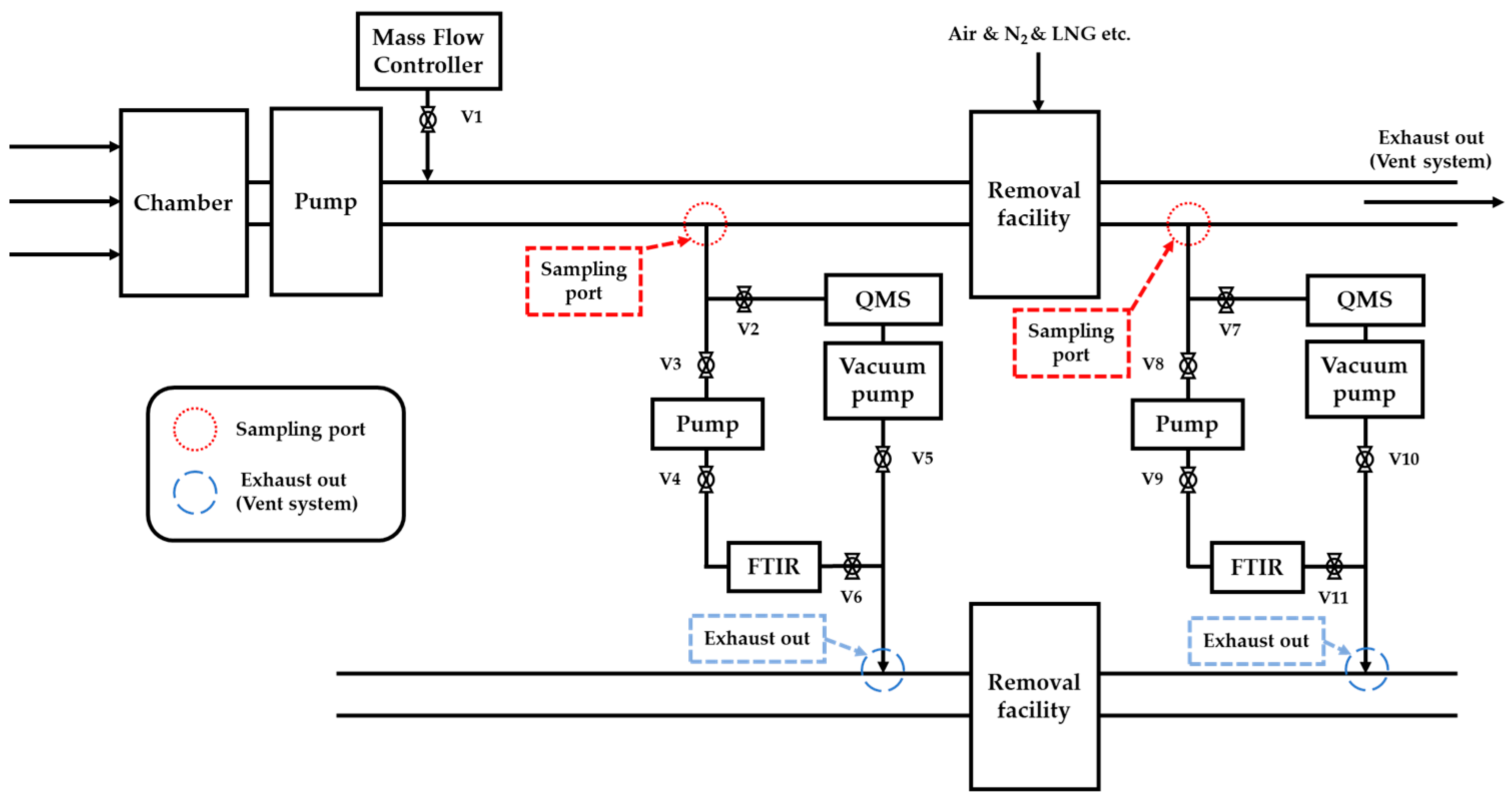
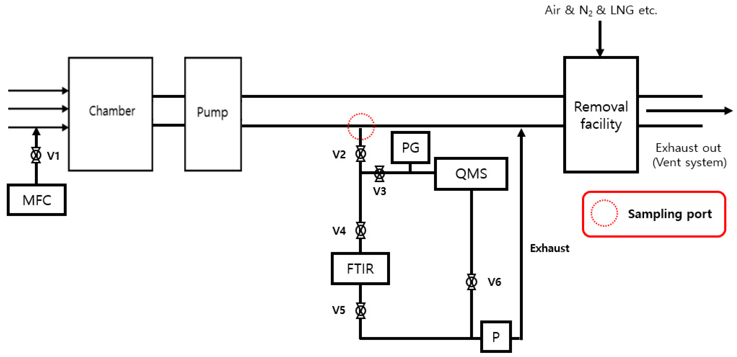
2.2.3. Improving DRE Measurements

To measure the DRE of the semiconductor and display manufacturing processes, the volume flow rate of the process gas was calculated by estimating the concentration of tracer gas, as mentioned in Section 2.2.2. Tracer gas is generally applied as an inert gas that interacts with other gases in the pipe and is not destroyed by the abatement system, and Kr (Krypton) gas is used among several inert gases because it must be applied as a gas that is not used in semiconductor and display manufacturing processes. Accordingly, tracer gas (Kr) is injected using a mass flow controller (MFC) at the front of the abatement system. However, an MFC is generally calibrated using nitrogen or compressed air and when an MFC is calibrated by nitrogen or when compressed air is used, the accuracy of the volume flow rate of Kr is decreased. Therefore, accurate measurements were only possible when the volume flow rate of Kr was corrected by applying the gas factor, as shown in Table 2, and the composition of internal process gas in the semiconductor and display industry is shown in Table S4.
Accurate measurements of the QMS for estimating the volume flow rate of process gas are only possible when samples are manufactured and equipment is calibrated, similar to the configuration of the actual internal process gas. Accordingly, a mixed standard gas similar to the composition of the process gas is produced, and the Kr concentration to be measured is diluted with N2, and then the true estimation values are calculated in Table 3 to draw comparisons with the measured values.
When Kr (99.999%) was injected into 1 SLM by estimating the volume flow rate of the process gas through the concentration measurement of Kr, measured concentrations were used to calculate the volume flow rate, according to Equation (1). In Experiment 1, when the volume flow rate was calculated, after calibration in consideration of only Kr without the composition of the process gas, the estimated true error value rate was 1.8 to 4.37% (Figure 2 and Table 4).
In Experiment 2, when all components of the mixed standard gas were calibrated to measure the Kr concentration, in light of the composition of the process gas, a normalization process was performed to estimate the volume flow rate of the process gas, and the error rate with true values was 0.74 to 2.26% (Table 5).
Experiments 1 and 2 confirmed that the concentration of Kr and the volume flow rate of process gas calculated through calibration based on Kr alone were accurately measured compared to the volume flow rate of the process gas. In addition, in order to confirm the accuracy of measurements, the estimated true value was analyzed by adding He gas to the mixed standard gas, as shown in Experiment 3, and, as the injected concentration of He gas increased, the normalization rate was found to also increase (Table 6 and Table S3 and Figure 3).
As a result, when performing the normalization process, considering unknown substances for accurate measurements, it is necessary to estimate the production of mixed standard gas after calibration by reflecting at least 85% of the process gas composition. It should be noted that when it is not reflected, the accuracy should be significantly lower than that of standard Kr materials manufactured from N2-based standard gas.

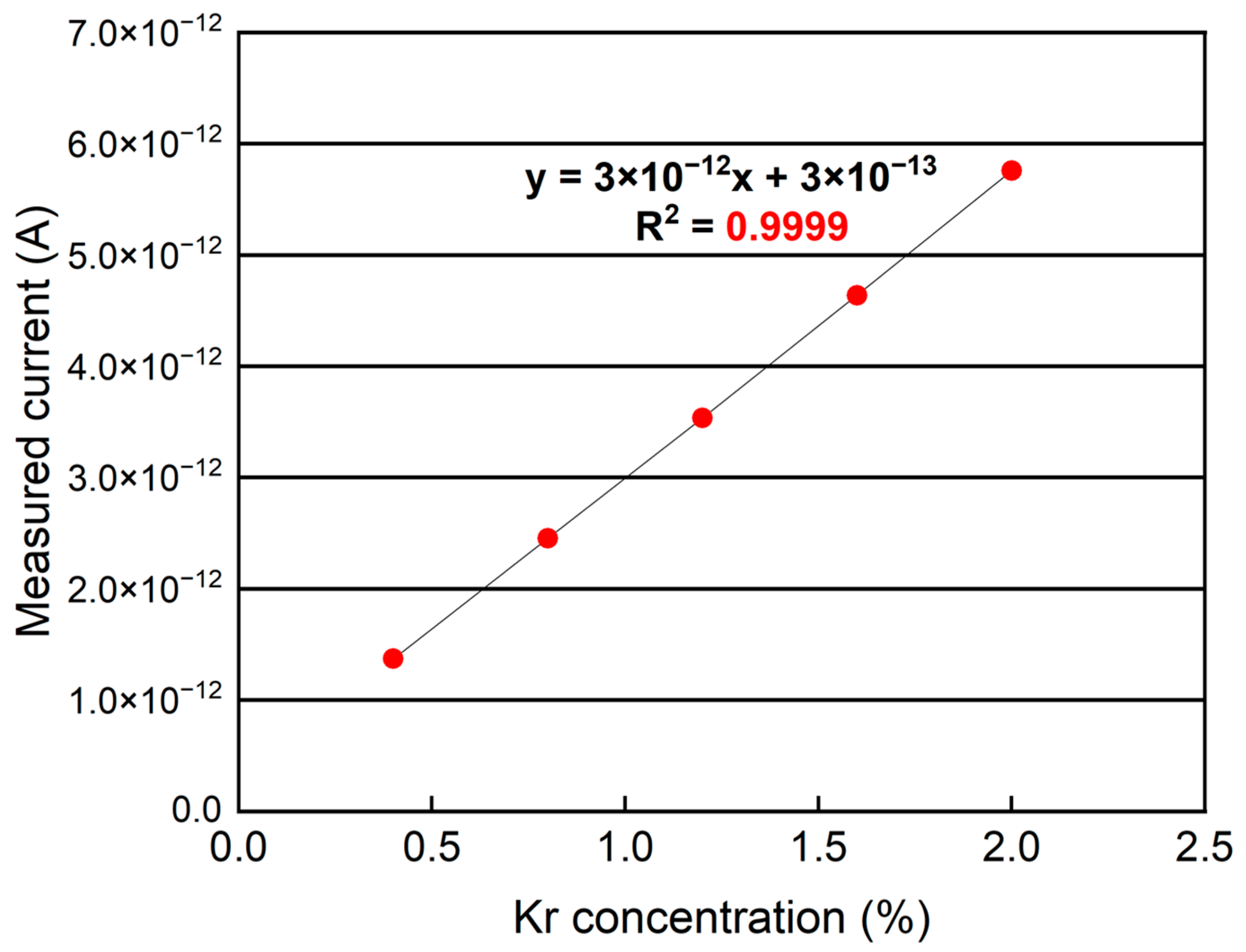
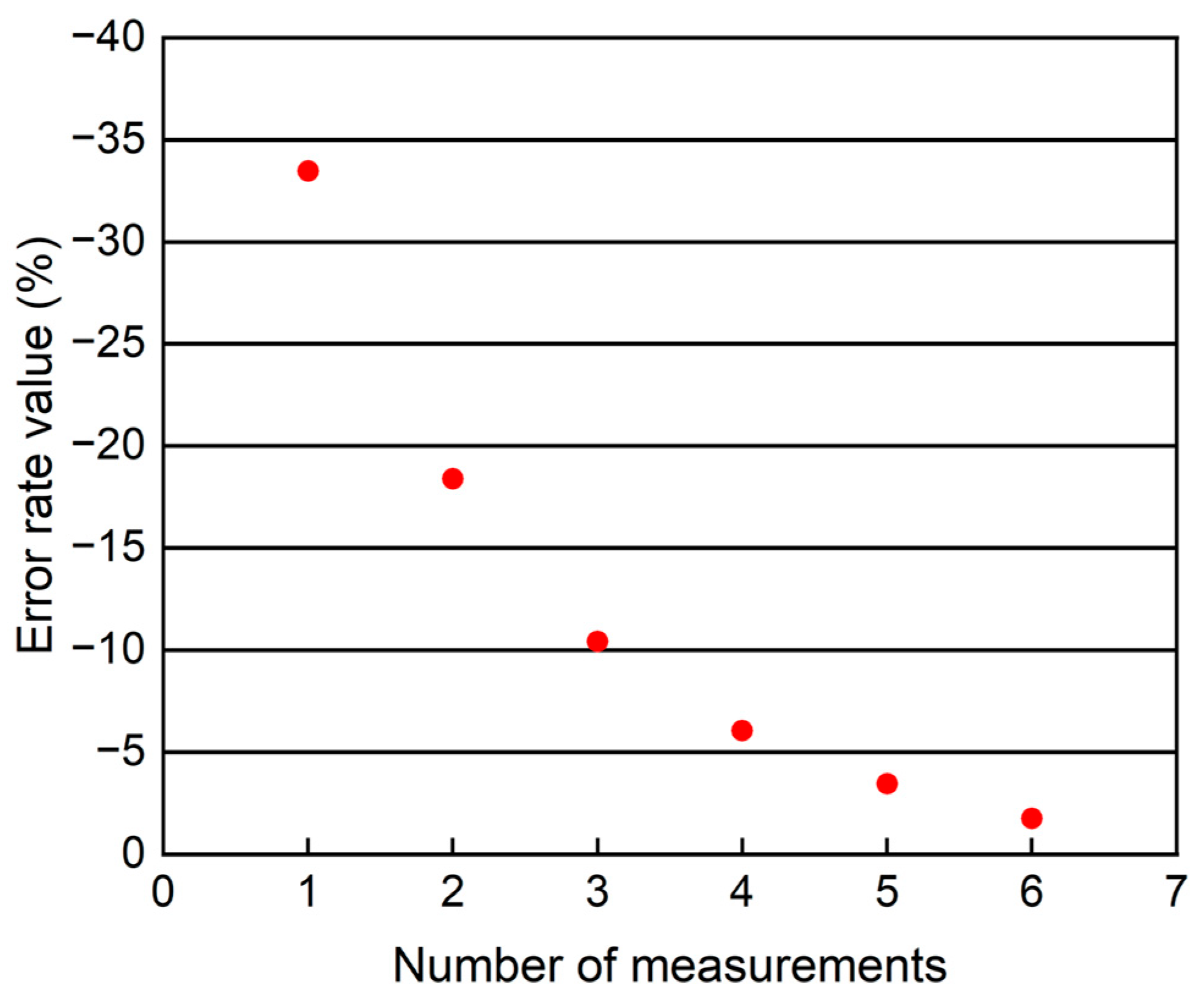
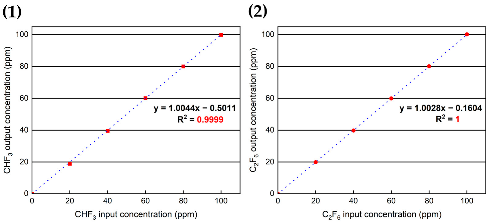
2.2.4. Validation of Improved Measurement

To confirm the validity of the improved measurement method, linearity, accuracy, precision, and verification and quantification limits were analyzed using CHF3 and C2F6. At first, to confirm linearity, measurements of 5-point concentration ranges (20, 40, 60, 80, and 100 ppm) of CHF3 and C2F6 were taken using certified reference material (CRM) of 100 ppm N2 balance. As a result, the correlation coefficient (R2) values of CHF3 and C2F6 confirmed that R2 values exceeded 99% or more (Figure 4).
Then, to confirm accuracy, the standard material of the median concentration for each item was analyzed four times using a CRM, and the average measurement value was divided by the median concentration value to obtain the results. This analysis was repeated 5 times with 60 ppm, which is the median concentration of CRM (100 ppm) from CHF3 and C2F6. Then, the average repeated analysis values were divided by the median concentration values (60 ppm) and calculated as a percentage. As a result, the accuracy values of CHF3 and C2F6 were calculated as 100.09 and 99.89%, respectively, showing that the accuracy of CHF3 and C2F6 was estimated within a validity range of 90–110%.
To confirm precision, repeatability and reproducibility were verified. Repeatability was determined by analyzing the standard material of the median concentration for each item 4 times using a standard gas, and calculating the relative standard deviation (RSD). In order to confirm the repeatability, the analysis was repeated 5 times with 60 ppm, which is the median concentration of CRM (100 ppm) of CHF3 and C2F6, and the RSD of analysis values were estimated. As a result, the RSDs of CHF3 and C2F6 were calculated as 0.07 and 0.03%, and the values were confirmed to be within a validity range of 5%.
Reproducibility was calculated over a 5-point concentration range using the CRM (100 ppm) of CHF3 and C2F6 by measuring four or more analyses from the testing laboratory and by performing analysis at different times. As a result, the accuracy measured to check the reproducibility of CHF3 and C2F6 was analyzed within the validity range of 90 to 110%.
Furthermore, the detection limit was analyzed based on a 500 cm gas cell. The detection limit was calculated by repeatedly measuring the concentration (that is twice that of the manufacturer’s provided detection limit) 7 times, and then multiplying the standard deviation by 3.14 to calculate the expanded uncertainty. The measurement equipment’s detection limits of CHF3 and C2F6 provided by the manufacturer were 1.5 and 0.5 ppm, and were calculated by multiplying the standard deviation of the values (3.14) measured 7 times at 3 ppm and 1 ppm, which are double the concentration values. As a result, the detection limit values of CHF3 and C2F6 were calculated as 1.00 and 0.55 µmol/mol.
In addition, the quantitative limit was calculated as 10 times that of the detection limit, and the quantitative limit values of CHF3 and C2H6 were estimated to be 3.19 and 1.75 µmol/mol. Overall, the validity of the improved measurement method was proven to be satisfied within the validity standard value range (Tables S6 and S7).

2.3. Use Rate of Gas (Ui)

2.3.1. Features of Characteristic Parameter

The use rate of gas (Ui) is the fraction of the injected GHG destroyed or transformed in the manufacturing process, such as etching and CVD. The use rate of gas can be determined depending on how optimized the process is. According to the 2019 IPCC Refinement, the use rate of the fluorinated gas varies on the gas type, process type, and wafer size (Tables S8 and S9).

2.3.2. Research on Improving the Use Rate of Gas (Ui) Measurements

In the case of measuring the use rate of gas (Ui), no research method or standardized method has been proposed. Accordingly, this study proposes various methods that can be used to measure the use rate of gas (Ui) and compare the measurement results.
The first method of measuring the use rate of gas (Ui) involves installing a sampling port at the inlet of the point-of-use (POU) scrubber and measure the FCs or N2O gas volume flow rate in the plasma (on/off state) of the main process using measurement equipment (QMS and FT-IR), as shown in Figure 5.
Figure 5. Diagram of measuring device installation for measuring the use rate of gas (Ui) [Method 1].
Applsci 13 08834 g005
F o n , o f f = S f ( o n , o f f ) C K r ( o n , o f f ) × 10 6
  • Fon,off: the inlet volume flow rate at on/off plasma (L/min);
  • Sf(on,off): the volume flow rate of tracer gas injected using an MFC at plasma (on/off state) (L/min);
  • CKr(on,off): the measured concentration of the tracer gas using the QMS at plasma (on/off state) (μmol/mol).
The volume flow rate of FCs or N2O gas is calculated from the estimated inlet volume flow rate.
V o n , o f f = C ( o n , o f f ) × F o n , o f f × 1000
  • Von,off: the inlet volume flow rate of FCs or N2O gas at plasma (on/off state) (sccm);
  • C(on,off): the measured concentration of FCs or N2O gas using the QMS at plasma (on/off state) (μmol/mol).
Therefore, the use rate of gas (Ui) is determined using Equation (8).
U i = V o f f V o n V o f f × 100   ( % )
  • Ui: the use rate of gas (%);
  • Voff: FC or N2O gas volume flow rate of plasma (off state) in the process chamber (sccm);
  • Von: FC or N2O gas volume flow rate of plasma (on state) in the process chamber (sccm).
The second method of measuring the use rate of gas (Ui) involves calculating and comparing the volume flow rate of the chamber using an MFC with FCs or N2O gas volume flow rate measured at the inlet of the removal facility (POU scrubber) during the operating process (Figure 6).
Figure 6. Diagram of measuring device installation for measuring the use rate of gas (Ui) [Method 2].
Applsci 13 08834 g006
F = S f C K r × 10 6
  • F: the inlet volume flow rate (L/min);
  • Sf: the volume flow rate of tracer gas injected using an MFC (L/min);
  • CKr: the measured concentration of tracer gas using the QMS (μmol/mol).
The volume flow rate of GHG emissions at the inlet is estimated from the calculated inlet volume flow rate.
V i n = C × F × 1000
  • Vin: the volume flow rate of FCs or N2O gas at the inlet (sccm);
  • C: the measured concentration of FCs or N2O gas at the inlet (μmol/mol).
Therefore, the use rate of gas (Ui) can be determined using Equation (11).
U i = V s V i n V s × 100   ( % )
  • Ui: the use rate of gas (%);
  • Vs: FCs or the N2O gas volume flow rate of GHGs from the main process (sccm);
  • Vin: FCs or the N2O gas volume flow rate of GHGs at the inlet (sccm).
The non-steady state process in Method 1 is approximately equal to the actual process gas supplement in Method 2. Therefore, Method 1 can be applied when the amount of GHGs supplied during the measurement time in the facility’s main process is provided and verified, and Method 2 can be applied when the number of FCs or the amount of N2O gas is impossible to provide.

2.3.3. Improved Measurement Validation

The validation and use rates (Ui) were confirmed simultaneously through an evaluation of the previously mentioned DRE measurements. It was also applied to the use rate of gas (Ui) and by-product emission factor (Bby-product, i) measurements, and the results mentioned in Section 2.2.4 were then verified.

2.4. By-Product Emission Factor (Bby-product, i)

2.4.1. Characteristic Parameter Features

The by-product emission factor (Bby-product, i) refers to the rate at which GHGs, that are injected into semiconductor and display manufacturing industries, are converted into a by-product, i.e., another GHG, via plasma operation, such as etching and CVD processes. According to the ’19 IPCC Refinement G/L, the by-product emission factor (Bby-product, i) of fluorinated gas varies depending on the process gas and the by-product gas, as shown in Tables S10–S15.

2.4.2. Research on Improving By-Product Emission Factor (Bby-product, i) Measurements

In the case of measuring the by-product emission factor (Bby-product, i), no research method or standardized method has been proposed. However, as mentioned in Section 2.3.2, measurements can be taken in the same way as the use rate of gas (Ui), showing differences in measuring the concentration of by-product gases instead of estimating the concentration of GHGs. The by-product emission factor (Bby-product, i) can be determined using Equations (12) and (13).
V b y p a s s = C b y p a s s × F × 1000
  • Vby-pass: the volume flow rate of by-product gas from the inlet of the abatement system (mL/min);
  • Cby-pass: the concentration of by-product gas as an FC from the abatement system (μmol/mol).
B i = V b y p a s s V s × 100   ( % )
  • Bi: the by-product emission factor during the manufacturing process (Bby-product, i);
  • Vs: the FC gas volume flow rate during the manufacturing process (mL/min).

2.4.3. Validation of Improved Measurements

The by-product emission factor (Bby-product, i) was also simultaneously validated through an evaluation of the DRE measurement method, as mentioned above, which was applied equally to the use rate of gas (Ui) and the by-product emission factor (Bby-product, i), and the results mentioned in Section 2.2.4 were then verified.

3. Results

3.1. Destruction Removal Efficiency (DRE)

3.1.1. Process of Measurement

To measure the efficiency of POU scrubbers used in the sectors, measurements were conducted on a plasma-type scrubber, and the key equipment used for estimation included two FT-IRs used to analyze GHG concentrations and two QMSs to analyze Kr gas concentrations. Four types of GHGs were measured: SF6, CF4, NF3, and N2O, and one type of Kr gas was used to calculate the volume flow rate of the inlet and the outlet. Then, FT-IR and QMS were calculated using two MFCs, secondary reference materials, and high-purity nitrogen (99.999%) gas as a reference of material-based gas (Figure 7).
The QMS was calibrated before measurements were taken in the field, and the reliability of FT-IR could be secured even when the data were calculated through post-calibration due to the nature of the equipment. The distance between the gas injection mini-chamber and inlet was more than 2 m, and QMS sampling and FT-IR sampling were performed by connecting 1/4-inch Teflon tubes to the inlet and outlet sampling ports. Before measurement were taken, in order to check the inside of the scrubber, 1 SLM of high-purity Kr gas and 100 SLM of N2 gas were injected to confirm that there was no change in the volume flow rate at the inlet and outlet, and then, the measurements were carried out. Furthermore, in order to check the volume flow rate, 30 SLM of N2 gas was additionally injected into the outlet, and the volume flow rates of the inlet and outlet were varied and estimated. The target gases to be measured were CH4 and NF3, which were measured once each, and measurements were taken seven times in total. One measurement time was 10 min, and the internal purging of FT-IR was performed using N2 gas at the end of each measurement.

3.1.2. Results of Measurement

In order to confirm the optimal conditions for each gas of the POU scrubber, the DRE for each volume flow rate and the consumption rates of plasma energy were measured. When the treatment volume flow rate of the POU scrubber increased to 300 SLM, it was confirmed that the DRE decreased to some extent. In particular, in the case of NF3, it was necessary to increase the energy consumption for optimal DRE conditions, and 300 SLM was set as the applicable optimal processing capacity in display sectors. The measurement results are shown in Table 7. As an additional experiment, the DRE, according to the treatment capacity of the POU scrubber, was estimated based on CH4, which was destroyed the least by the POU scrubber, and the measurement results are shown in Table 7 and Table 8.

3.2. Use Rate of Gas (Ui)

As mentioned in Section 2.2.2, using Methods 1 and 2 proposed in the research based on improving measurements for the use rate of gas (Ui). In the display sector, the use rate of gas (Ui) was estimated for the CVD process of N2O gases, whose usage has increased alongside the production of OLED. The measurement results are shown in Table 9.

3.3. By-Product Emission Factors (Bby-product, i)

For the fluorinated greenhouse gases (F-GHGs) of C2 or higher, which are widely used in semiconductor and display manufacturing processes, by-product emission factors (Bby-product, i) for each by-product gas that could be generated based on plasma were measured, and by-product emission factors (Bby-product, i) for each by-product gas that could be generated under various conditions are shown in Table 10.

3.4. Results on the DRE, Use Rate of Gas (Ui), and By-Product Emission Factor (Bby-product, i) Measurements

According to DRE measurement results, a comparison was performed with the ’06 IPCC G/L and ’19 IPCC Refinement to the ’06 IPCC G/L for National Greenhouse Gas Inventories, as shown in Table 11. It was confirmed that DRE showed a large difference in volume flow rate, gas type, and energy consumption data in the manufacturing process. As a result, since DRE coefficients for each gas presented in the IPCC G/L considered and presented only the type of gas, it is necessary to develop coefficients based on various facility conditions in order to apply DRE that is suitable for the site.
According to results on the use rate of gas (Ui) measurements, the EPA 40 U.S. Code of Federal Regulation’s (CFR) Part 98 was compared against the ’19 IPCC Refinement to the ’06 IPCC G/L for National Greenhouse Gas Inventories, as shown in Table 12. The use rate of gas showed that the recipes varied depending on the characteristics of each manufacturing process and the product being made. As a result, our analysis showed a large difference based on the input of optimal or excessive gases for each characteristic of product, and then it was found that it was necessary to develop coefficients based on these differences.
According to the results of by-product emission factor (Bby-product, i) measurements, the ’06 IPCC G/L and ’19 IPCC Refinements were compared to the ’06 IPCC G/L for National Greenhouse Gas Inventories, as shown in Table 13. The by-product gas’ generated rate showed a large difference based on gas type and the amount of energy assumption, similar to the DRE, and the by-product gas’ generated rate presented in the IPCC G/L was presented as coefficients with various process conditions. We also found that it was necessary to improve coefficients based on various facility conditions.

4. Conclusions

In summary, we presented accurate measurement methods centered around DRE, the use rate of gas (Ui), and by-product emission factors (Bby-product, i), which are characteristic parameters used for estimating GHG emissions in the semiconductor, and display industry and fluorine-based GHGs used in the electronics manufacturing processes were measured at Korea’s various facilities. As a result, it was confirmed that GHG emissions and national GHG emissions are overestimated compared to the reduction and emission factor of ’06 IPCC G/L and ’19 IPCC G/L Refinement that are currently used to calculate GHG emissions in the Republic of Korea. Through this study, based on the established GHG emission calculation characteristic parameters in semiconductor and display industries, the need for re-establishment based on the facility’s applicability of various coefficients presented in the EPA 40 U.S. Code of Federal Regulations (CFR) (part 98; Subpart Ⅰ) was confirmed by comparing the ’06 IPCC G/L and ’19 IPCC Refinement to the ’06 IPCC G/L for National Greenhouse Gas Inventories. Furthermore, by measuring the destruction removal efficiency (DRE), the use rate of gas (Ui), and the by-product emission factor (Bby-product, i) data for GHGs that are used in the manufacturing process in semiconductor and display industries, but not presented in IPCC G/L, the need for additional study to prevent any overestimation of GHG emissions in the Republic of Korea’s semiconductor and display industries was made more apparent. Furthermore, we believe that reduction and emission factors that are unique to the Republic of Korea and that are more accurately established through additional measurements of GHGs used in semiconductor and display manufacturing processes in Korea, as well as research on characteristic parameters, can significantly help to reduce national GHG emissions, providing a good frame of references for countries that need to develop country-specific reduction and emission factors.

Supplementary Materials

The following supporting information can be downloaded at: https://www.mdpi.com/article/10.3390/app13158834/s1. Table S1: Composition of Tiers 1, 2, and 3 in the electronics industry based on emission sources using guidelines for estimating and reporting greenhouse gas (GHG) emissions. Table S2: The detection limits (DLs) of FT-IR for each gas cell. Table S3: The classification of applicable FT-IR gas cell lengths according to scrubber type. Table S4: The gas composition of internal process gas in the electronics manufacturing process. Table S5: Gas compositions according to He gas injections for Experiment 3. Table S6: Measurements on comparing the validity (CHF3) of results between analysts to confirm the precision (reproducibility). Table S7: Measurements on comparing the validity (C2F6) of results between analysts to confirm precision (reproducibility). Table S8: Default use rate factors for GHG emissions in the semiconductor industry. Table S9: Default use rate factors for GHG emissions in the display industry. Table S10: GHG default emission factors for by-product generation rates in the semiconductor industry (Tier 2a). Table S11: GHG default emission factors for by-product generation rates in the semiconductor industry (Tier 2b, wafer-size, i.e., less than 200mm). Table S12: GHG default emission factors for by-product generation rates in the semiconductor industry (Tier 2b, wafer-size, i.e., 300mm). Table S13: GHG default emission factors for by-product generation rates in the semiconductor industry (Tier 2c, wafer-size, i.e., less than 200mm). Table S14: GHG default emission factors for by-product generation rates in the semiconductor industry (Tier 2c, wafer-size, i.e., 300 mm). Table S15: GHG default emission factors for by-product generation rates in the display industry (Tier 2c).

Author Contributions

All authors contributed to the research presented in this study. Conceptualization and methodology, B.-J.L.; writing—original draft preparation, B.-J.L. and I.-K.J.; writing—review and editing, S.-Y.Y. and J.K.; analysis, I.-K.J., Y.H., and J.-H.P. All authors have read and agreed to the published version of the manuscript.

Funding

This study was funded by Korea Environment Industry and Technology Institute (KEITI) and Korea Ministry of Environment (MOE) (no. 2022003560008).

Institutional Review Board Statement

Not applicable.

Informed Consent Statement

Not applicable.

Data Availability Statement

Not applicable.

Acknowledgments

This work was financially supported by Korea Environment Industry and Technology Institute (KEITI) as “Climate Change R&D Project for New Climate Regime”, and by the Korea Ministry of Environment (MOE).

Conflicts of Interest

The authors declare no conflict of interest.

References

  1. Nam, S.-E.; Park, A.; Park, Y.-I. Separation and Recovery of F-gases. Membr. J. 2013, 23, 189–203. [Google Scholar]
  2. Jang, S.-S.; Han, J.-K.; Cho, H.-I.; Lee, S.-K. A Study on the Destruction or Removal Efficiency of Toxic Gas Reduction Facilities in Semiconductor and Display Industries. J. Korean Inst. Gas 2017, 21, 88–95. [Google Scholar]
  3. Hong, Y.C.; Uhm, H.S. Abatement of CF4 by atmospheric-pressure microwave plasma torch. Phys. Plasmas 2003, 10, 3410–3414. [Google Scholar] [CrossRef]
  4. Hong, Y.C.; Uhm, H.S.; Chun, B.J.; Lee, S.K.; Hwang, S.K.; Kim, D.S. Microwave plasma torch abatement of NF3 and SF6. Phys. Plasmas 2006, 13, 033508. [Google Scholar] [CrossRef]
  5. Ko, D.G.; Ko, S.J.; Choi, E.K.; Min, S.G.; Oh, S.H.; Jung, J.; Kim, B.M.; Im, I.-T. Perfluorocarbon Destruction and Removal Efficiency: Considering the By-products and Energy Consumption of an Abatement System for Microelectronics Manufacturing. IEEE Trans. Semicond. Manuf. 2014, 27, 456–461. [Google Scholar] [CrossRef]
  6. UNFCCC. Good Practice Guidance and Uncertainty Management in National Greenhouse Gas Inventories; Intergovernmental Panel on Climate Change: Geneva, Switzerland, 2000.
  7. Houghton, J.T. Climate Change 1995: The Science of Climate Change; Cambridge University Press: New York, NY, USA, 1996. [Google Scholar]
  8. Lee, H.M.; Chang, M.B.; Lu, R.F. Abatement of Perfluorocompounds by Tandem Packed-Bed Plasmas for Semiconductor Manufacturing Processes. Ind. Eng. Chem. Res. 2005, 44, 5526–5534. [Google Scholar] [CrossRef]
  9. Jeon, E.-C.; Myeong, S.; Sa, J.-W.; Kim, J.; Jeong, J.-H. Greenhouse gas emission factor development for coal-fired power plants in Korea. Appl. Energy 2010, 87, 205–210. [Google Scholar] [CrossRef]
  10. Lee, S.; Kim, J.; Lee, J. Development of CO2 emission factors from a large circulating fluidized bed boiler. Energy Sources 2016, 38, 1262–1268. [Google Scholar] [CrossRef]
  11. Cho, C.; Kang, S.; Kim, M.; Hong, Y.; Jeon, E.-C. Uncertainty Analysis for the CH4 Emission Factor of Thermal Power Plant by Monte Carlo Simulation. Sustainability 2018, 10, 3448. [Google Scholar] [CrossRef] [Green Version]
  12. Kang, S.; Cho, S.; Roh, J.; Jeon, E.-C. Analysis of Main Factors for CH4 Emission Factor Development in Manufacturing Industries and Construction Sector. Energies 2020, 13, 1220. [Google Scholar] [CrossRef] [Green Version]
  13. Kang, S.; Kim, S.-D.; Jeon, E.-C. Emission Characteristics of Ammonia at Bituminous Coal Power Plant. Energies 2020, 13, 1534. [Google Scholar] [CrossRef] [Green Version]
  14. Lee, S.; Kim, J.; Lee, J.; Lee, S.; Jeon, E.-C. A study on the evaluations of emission factors and uncertainty ranges for methane and nitrous oxide from combined-cycle power plant in Korea. Environ. Sci. Pollut. Res. 2013, 20, 461–468. [Google Scholar] [CrossRef] [PubMed] [Green Version]
  15. IPCC. 2019 Refinement to the 2006 IPCC Guidelines for National Greenhouse Gas Inventories. In Electronics Industry Emissions; Intergovernmental Panel on Climate Change: Geneva, Switzerland, 2019; Volume 3, Chapter 6. [Google Scholar]
  16. ISMI. Guideline for Environmental Characterization of Semiconductor Process Equipment—Revision 2; Technology Transfer #06124825B-ENG; International SEMATECH Manufacturing Initiative: Austin, TX, USA, 2009. [Google Scholar]
  17. IPCC. 2006 IPCC Guideline for National Greenhouse Gas Inventories. In Electronics Industry Emissions; Intergovernmental Panel on Climate Change: Geneva, Switzerland, 2007; Volume 3, Chapter 6. [Google Scholar]
  18. Lee, J.-Y.; Lee, J.B.; Moon, D.M.; Souk, J.H.; Lee, S.Y.; Kim, J.S. Evaluation Method on Destruction and Removal Efficiency of Perfluorocompounds from Semiconductor and Display Manufacturing. Bull. Korean Chem. Soc 2007, 28, 1383. [Google Scholar]
  19. Yang, C.-F.O.; Kam, S.-H.; Liu, C.-H.; Tzou, J.; Wang, J.-L. Assessment of removal efficiency of perfluorocompounds (PFCs) in a semiconductor fabrication plant by gas chromatography. Chemosphere 2009, 76, 1273–1277. [Google Scholar] [CrossRef] [PubMed]
  20. US EPA. Protocol for Measuring Destruction or Removal Efficiency (DRE) of Fluorinated Greenhouse Gas Abatement Equipment in Electronics Manufacturing; EPA: Washington, DC, USA, 2010.
  21. Korea Ministry of Environment. Measurement Method for Volumetric Flow Rate of Non-CO2 GHG(CF4, NF3, SF6, N2O) in Semiconductor and Display Process, KS I 0587; Korea Ministry of Environment: Sejong-si, Republic of Korea, 2018.
  22. NIER. A Study on the Destruction or Removal Efficiency of Greenhouse Gases Reduction Facilities in Semiconductor and Display Industries; NIER: Shortland, Australia, 2015. [Google Scholar]
  23. US EPA. 40 CFR Part 98 Subpart Ⅰ Electronics Manufacturing Title 40—Protection of Environment Chapter Ⅰ Environmental Protection Agency, Subchapter C-Air Programs, Part 98—Mandatory Greenhouse Gas Reporting; EPA: Washington, DC, USA, 2011.
  24. EPA. Developing a Reliable Fluorinated Greenhouse Gas (F-GHG) Destruction or Removal Efficiency (DRE) Measurement Method for Electronics Manufacturing: A Cooperative Evaluation with IBM (EPA 430-R-10-004); EPA: Washington, DC, USA, 2009.
  25. EPA. Developing a Reliable Fluorinated Greenhouse Gas (F-GHG) Destruction or Removal Efficiency (DRE) Measurement Method for Electronics Manufacturing: A Cooperative Evaluation with NEC Electronics, Inc. (EPA 430-R-10-005); EPA: Washington, DC, USA, 2008.
Figure 1. Diagram of measuring device installation for measuring DRE.
Applsci 13 08834 g001
Figure 2. The error rate graph comparing true values using tracer gas (Kr) (Experiment 1).
Applsci 13 08834 g002
Figure 3. Error rate graph for comparing injected He concentration variations.
Applsci 13 08834 g003
Figure 4. The linearity result graphs of (1) CHF3 and (2) C2F6 to confirm validity.
Applsci 13 08834 g004
Figure 7. Diagram for measuring destruction removal efficiency (DRE).
Applsci 13 08834 g007
Table 1. Default DRE factors for GHG emissions in semiconductor and display industries.
GasDRE
CF40.89
C2F60.96
C3F80.95
C4F60.99
c-C4F80.98
C4F8O0.98
C5F80.98
CHF30.98
CH2F20.98
CH3F0.98
CH2F50.95
NF30.95
SF60.95
N2O0.60
Table 2. Gas factors in nitrogen calibration standard using inert gas.
Inert GasGas Factors in Nitrogen
Calibration Standard
He1.386
Ne1.398
Kr1.382
Xe1.383
Table 3. Composition of prepared mixed standard gas and comparison with measured values through dilution of N2.
Volume Flow Rate
(N2, SLM)
Volume Flow Rate
(Standard, SLM)
Concentration (%)
551.01
371.414
Mixed Standard Gas
KrN2O2ArCO2Cylinder No.
2.0287.759.010.600.42N1030
Internal temperature in lab: −20 °C. MFC—calibrated product using compressed air. Assumption for volume flow rate calculation of injected Kr (99.999%) gas: 1 SLM.
Table 4. Arithmetic error rate values compared to true values in Experiment 1.
N2STD GasPre-Set Kr
Concentration (%)
Measured Kr Concentration (%)Gas FactorTemperature and
Pressure
Calibration
Measured Volume Flow Rate (SLM)Calculated True Value of
Volume Flow Rate
Error Rate (%)
730.60.6271.3821.073236.413247.24.37
551.01.0271.3821.073144.369148.32.67
371.41.4251.3821.073104.036105.91.80
Table 5. Arithmetic error rate values compared true values in Experiment 2.
N2STD GasPre-Set Kr Concentration (%)Measured Kr Concentration (%)Gas FactorTemperature and Pressure CalibrationMeasured Volume Flow Rate (SLM)Calculated True Value of Volume Flow RateError Rate (%)
730.60.6131.3821.073241.612247.22.26
551.01.011.3821.073146.493148.31.23
371.41.4101.3821.073105.166105.90.74
Table 6. Injected He gas concentration variations and their corresponding error rates.
He Gas Concentration (%)Error Rate (%)
67.4628.62
58.0236.92
47.9545.78
37.2055.24
25.6865.37
13.3176.24
Table 7. Comparison of DRE values according to the volume flow rate variation in the POU scrubber based on the applicability to the display sector.
Volume Flow RateGasPower Value (kW)FT-IR (ppm)QMS (SLM)DRE
(%)
InletOutletInletOutlet
100 SLMSF67.0955998.840.3710014399.99
10.735998.84NA10014399.99
NF36.0584109.57NA10014399.99
10.734109.57NA10014399.99
300 SLMSF66.0325414.71163.8432236596.57
10.735414.71NA32236599.99
NF36.0583786.961640.3032236549.32
10.733786.96143.3332236595.57
Table 8. Comparison of DRE values according to volume flow rate variation in the POU scrubber based on the applicability to the semiconductor sector.
Volume Flow RateGasPower Value (kW)FT-IR (ppm)QMS (SLM)DRE
(%)
InletOutletInletOutlet
100 SLMCH48.085637.561086.1010014372.45
9.225637.56574.4310014385.43
10.105637.56275.4310014393.01
10.735637.56173.4610014395.60
130 SLMCH410.105593.821254.1013017569.77
10.735593.821067.5713017574.31
12.1045593.82620.4613017585.07
14.5085593.8296.7513017597.67
150 SLMCH414.5085565.99385.2415019091.23
15.125565.99280.1215019093.63
15.845565.99149.4515019096.60
Table 9. The use rate of gas (Ui) from N2O gas using the CVD process in the display industry.
Method 1Method 2
Plasma OnPlasma OffUse Rate of Gas (%)Injected Volume Flow Rate
(sccm)
Plasma OnUse Rate of Gas (%)
Volume Flow Rate (sccm)Volume Flow Rate (sccm)Volume Flow Rate (sccm)
86,09272,33916.085,00072,33914.9
85,56173,31114.385,00073,31113.8
Table 10. By-product gas emissions generated from a plasma scrubber.
GasPower Value (kW)FT-IR (ppm)DRE
(%)
By-Product Gas
InletOutletCF4
(ppm)
C2F6
(ppm)
CHF3
(ppm)
C2F66.0324273.381942.3148.48764.32--
8.084331.561599.5358.141423.73--
10.734334.331117.9570.762333.24--
CHF36.0325150.921707.5962.40576.91109.88-
8.085150.921162.3274.42783.09168.75-
10.735150.92587.9387.07887.91154.32-
C3F86.0322946.141602.2138.351397.8927.1310.03
8.082946.14985.5462.082214.25179.296.52
10.732946.14482.1281.453256.02487.922.24
Table 11. Comparison of DRE values between the presented IPCC guideline’s factor values (’06 and ’19) and measured DRE values in this study.
SectorGasVolume Flow Rate
(SLM)
Power Value (kW)DRE (%)
This Study’06 IPCC’19 IPCC
SemiconductorCF41008.0872.4590.0089.00
9.2285.43
10.1093.01
10.7395.60
13010.1069.77
10.7374.31
12.10485.07
14.50897.67
15014.50891.23
15.1293.63
15.8496.60
DisplaySF61007.09599.9990.0095.00
10.7399.99
3006.03296.57
10.7399.99
NF31006.03299.9995.0095.00
10.7399.99
3006.05849.32
10.7395.57
Table 12. Comparison of the use rate of gas (Ui) measurements between the presented EPA and ’19 IPCC guidelines and the use rate of gas (Ui) measurements in this study.
SectorGasUse Rate of Gas (%)
This StudyEPA’19 IPCC
DisplayN2O14.940.037.0
13.8
Table 13. Comparison between by-product emission factor (Bby-product, i) measurements and IPCC guidelines’ factor value measurements (’06 and ’19) presented in this study.
SectorGasPower Value (kW)By-Product Emission Factors (Bby-product, i)
(Target Gas/By-Product Gas)
CF4 (%)C2F6 (%)CHF3 (%)
DisplayC2F66.03217.65--
8.0832.87--
10.7353.87--
6.03211.202.13-
CHF38.0815.203.28-
10.7317.243.00-
6.03247.450.920.34
C3F88.0875.166.090.22
10.73110.5216.560.08
Disclaimer/Publisher’s Note: The statements, opinions and data contained in all publications are solely those of the individual author(s) and contributor(s) and not of MDPI and/or the editor(s). MDPI and/or the editor(s) disclaim responsibility for any injury to people or property resulting from any ideas, methods, instructions or products referred to in the content.

