1. Introduction
Magnetic domains are of high interest to researchers due to both the bright underlying physics that governs their organization, and because of an important role played by domains in a lot of applications of magnetic nano- and microstructures [
1]. One of the most studied and attractive objects here are the crystalline ferrimagnetic iron garnet films that combine strong magnetooptical (MO) activity with high transparency in the red and infrared spectral ranges, pronounced mechanical properties, and the ability to control the parameters of the MO spectra by modification of their chemical composition [
2,
3,
4,
5]. It is generally recognized that garnets are widely used as optical disks [
6], resonators [
7], and in microwave devices [
8]. Moreover, they are known as an efficient platform for spintronic and magnonic devices due to their exciting ability for the transport and processing of spin waves [
9,
10,
11].
The most important properties of garnets are determined to a large extent by their domain organization, which is governed by many parameters such as the crystallographic symmetry, type and concentration of dopants, magnetic and crystalline anisotropy, demagnetization fields, etc. [
1,
2,
12,
13]. As the properties of the surface and bulk magnetic domains are interconnected, their study is an interesting research task. Furthermore, the development of efficient experimental methods for the visualization of magnetic domains in the surface and bulk areas of garnet films seems also to be quite important.
The best-known approaches here are the polarization-sensitive magnetooptical microscopy typically performed in the Faraday or Voigt geometries [
14,
15], X-ray diffraction techniques, first of all the surface-sensitive Lorentz microscopy [
16,
17], and magnetic force microscopy (MFM) [
18,
19]. In the case of yttrium iron garnet films with perpendicular magnetic anisotropy, the Lorentz microscopy allows to study the magnetic domains at the nanoscale. It also revealed an important role played by the demagnetization field in the formation if domains and domain walls dynamics [
20]. These studies involved the high spatial resolution of the Lorentz microscopy technique (that is below 100 nm), and the temporal resolution of this surface sensitive probe can be made less than 1 ps [
21]. This allows the study of spin relaxation dynamics and the domain wall’s motion under the application of the external magnetic field. The magnetic force microscopy technique allows the visualization of complicated fractal-like and closure domains at the surface of epitaxial garnet films that are absent in bulky materials; it was recognized that the shape of the surface domains depend on the films’ thickness and composition [
22].
A special place is occupied by the optical second harmonic generation (SHG) [
23], which has been shown to provide giant values of magnetooptical effects in the SHG response predicted prior to their experimental observation [
24,
25]. It is also known for its high surface sensitivity if being applied to materials with intrinsic inversion symmetry [
26,
27,
28,
29,
30]. In the case of iron garnet films, the application of the SHG technique is beneficial due to (i) symmetry forbiddance of the even-order nonlinear optical effects (including SHG) in the bulk of centrosymmetric materials such as yttrium iron garnet crystals (in the electric dipole approximation), which provides high SHG sensitivity to the properties of the interface regions with inevitably broken inversion symmetry [
23,
31,
32], (ii) absence of the SHG contribution from the substrates, which is typically centrosymmetric gallium-gadolinium garnet (GGG) of a few hundreds of microns in thickness and which can also reveal weak MO responses, (iii) the large value of the MO effects in the SHG response and (iv) larger (as compared to the linear MO microscopy) SHG spatial resolution originating from the nonlinear nature of the effect, and (v) the ability to use a multiple-color pump and probe experimental schemes. As an example, magnetic domains were visualized via the SHG microscopy in [
33] in the scheme of the magnetooptical Faraday effect in iron garnet films of different crystallographic orientations, which provided additional information on the domain’s magnetization distribution as compared to a linear magnetooptical probe. Symmetry analysis of the magnetic nonlinear optical response at the SHG wavelength was discussed in detail in [
34,
35]. It was underlined that high-rank tensors describing different components of the SHG process that are of the first and of second orders in magnetization
, as well as induced by gradients of
, can be used for a thorough characterization of the residual magnetic structure of garnets and other objects.
Third-order nonlinear optical spectroscopy is also a well recognized and powerful technique [
36] that is widely applied to the studies of biological objects and tissues [
37,
38], resonant and local field effects in non-magnetic nanostructured objects [
39] and metasurfaces [
40,
41]. One of substantial benefits of this probe is an intrinsic usage of the two-color scheme. In that case, no laser-induced damage is expected if a tissue is transparent to the intense laser radiation of the infrared spectral range, while a much less intense third harmonic of visible or UV radiation and which is specific to a concrete type of a tissue, enables label-free visualization of biological structures on the scales down to a cell size. At the same time, to the best of our knowledge, magnetization-induced third-order nonlinear optical effects, including third harmonic generation (THG), have not been applied to the studies of magnetic microstructures. This can be due in part to the low values of the magnetization-induced effects in THG as compared to the case of SHG, as was demonstrated in [
31] for the case of metallic magnetic nanostructures.
Recently it was shown that the SHG microscopy can distinguish stripe domains in the bulk of garnet films, as well as the closure domains at the outer garnet/air interface [
42]. At the same time, the domain structure of the hidden interface of the ferrimagnetic film with the substrate remained unexplored. In this paper we apply magnetization-sensitive nonlinear optical microscopy to the study of magnetic ordering at the garnet/GGG interface and show that it reveals a complicated domain structure similar to that of the garnet/air one. Another finding is the extension of the magnetization-sensitive nonlinear optical microscopy method to the case of third harmonic generation, which shows higher resolution as compared to the case of the SHG probe.
2. Experimental Procedure and Samples under Study
Experiments were performed for 10 μm thick
epitaxial films grown by liquid phase epitaxy on a (111) facet of centrosymmetric GGG substrates.
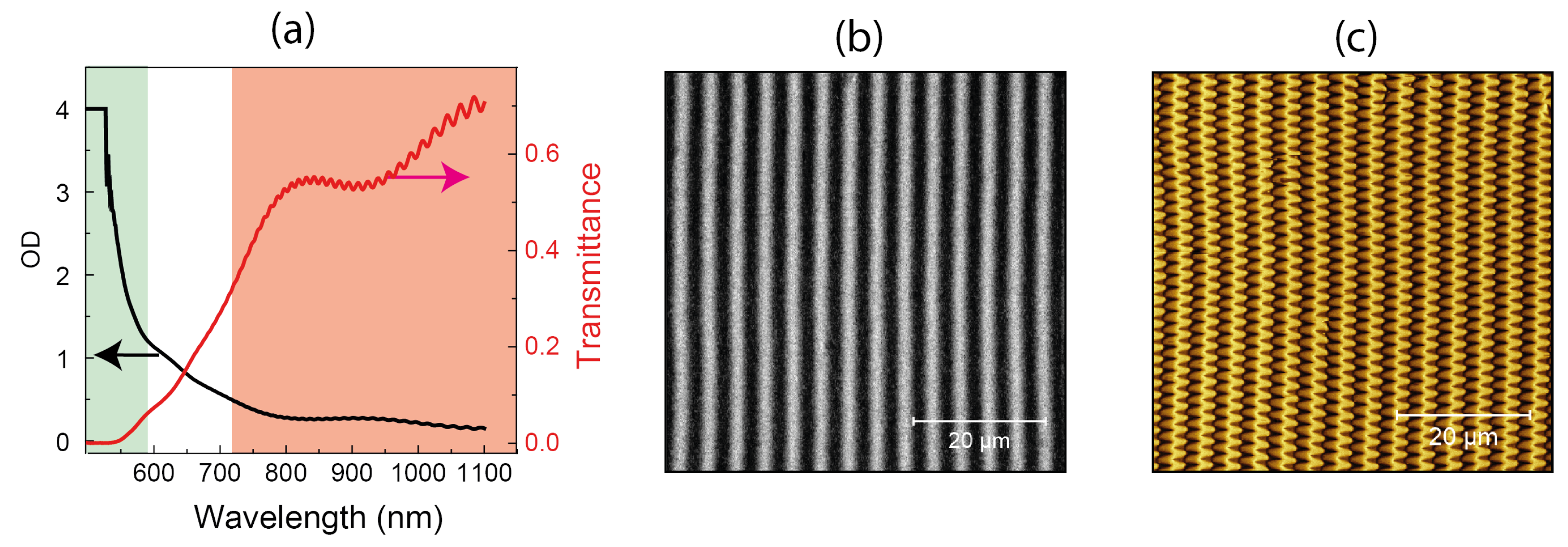
Figure 1a shows the transmission and optical density (OD) spectra of the studied samples, which reveal high absorption at the wavelengths below 600 nm that is typical for garnet films [
2]. Namely, the absorption coefficient in the blue spectral range is about four orders of magnitude larger as compared to the wavelength in the near-IR spectral range, which is rather important for the nonlinear optical experiments.
Magnetic force microscopy (MFM) experiments of the garnet films were performed using the set-up described in detail in [
42]. In brief, we used the atomic force microscope SmartSPM (AIST-NT, now produced by HORIBA Scientific) with a special magnetic tip composed of a multilayered
film, the thickness of the corresponding layers in Angstrom is denoted in brackets. Such a composition of the sensitive layer of the tip provided, first, the perpendicular magnetic anisotropy of the film and, second, its small magnetic moment. As a result, the magnetic structure of the studied sample was not disturbed during the MFM measurements.
MFM images of films were obtained in a standard two-pass technique (the so called lift mode), when at the first step the topography of the studied sample is recorded followed by the registration of the magnetic response in the constant distance surface-probe mode at the second step. Our measurements have shown that the films are flat, the root mean square average of the profile height deviations from the mean value (RMS) being about 1 nm. It is worth noting that the MFM probe reveals the distribution of the magnetic stray field along the normal to the surface, while the field associated with the in-plane components of magnetization remain much less pronounced in the MFM profile.
For the nonlinear optical microscopy studies, we used the radiation of an optical parametric oscillator (OPO) system Topol 1050-C (Avesta) with the laser pulse duration of up to 180 fs, wavelength tunable in the spectral range from 740 nm up to 1800 nm, and the mean power of 100 mW. The pump radiation was focused by a Nikon Plan Apo 60× oil objective with the NA = 1.4 in a spot of about 0.7–0.8 μm in diameter, which provided the waist length of the laser beam of a few micrometers, depending on the wavelength of the laser radiation. Mitutoyo M Plan Apo 100x objective with the NA = 0.7 was used for gathering the transmitted radiation at the second or third harmonic’s wavelengths, the nonlinear optical signal being detected by the Hamamatsu R4220 photomultiplier (PMT). In our experiments, the film was fixed at the Ratis three-axes piezo scanner stage, providing the positioning accuracy of a few nanometers. Polarizations of the input and harmonics’ radiation were controlled by the Glan–Taylor calcite polarizers and the necessary set of color filters placed in front of the PMT were used to block the pump beam passing through the garnet layer.
In accordance with the transmission spectrum of the
layer shown in
Figure 1a, the studied garnet films are transparent for the fundamental laser radiation in the whole tuning range marked by red in
Figure 1a, while second and third harmonics’ wavelengths typically fall into the absorption band. This allows the study of the nonlinear and magnetic properties of the interfaces of garnet films with the surrounding media (air and GGG) using the SHG or THG microscopy technique. Besides the evidently high in-plane spatial resolution of the nonlinear optical probe provided by strong focusing of the pump radiation, the in-depth resolution is mostly determined by small escape lengths at harmonics’ frequences at the wavelengths shorter than 600 nm. Importantly, the in-depth resolution of the nonlinear microscopy techniques exceeds that of the linear optical one due to the nonlinear dependence of the response on the pump intensity; the higher the order of the nonlinearity, the stronger the spatial localization of the nonlinear optical response at the second or third harmonics’ wavelengths.
3. Experimental Results
Figure 1b shows the optical transmission image of the studied
film in the absence of the external magnetic field for the crossed polarizations of the incident and transmitted beams. Dark and light regions on the Figure correspond to stripe domains in the bulk of the garnet film with the period of the domain structure of about 4.4 μm; the contrast in the image appears as the result of the opposite in sign Faraday rotation in the adjacent domains with residual magnetization oriented predominantly along the normal to the garnet layer.
A magnetic force microscopy image of the (outer)
/air interface measured over the 20 μm × 20 μm surface area is shown in
Figure 1c. Besides the periodic magnetic structure associated with the aforementioned stripe domains, it reveals a zigzag-like pattern with the period of approximately 1.6 μm associated with the block blind domains. It is worth noting that the high contrast of the MFM signal from the adjacent domains indicate the predominant perpendicular magnetic anisotropy of the film.
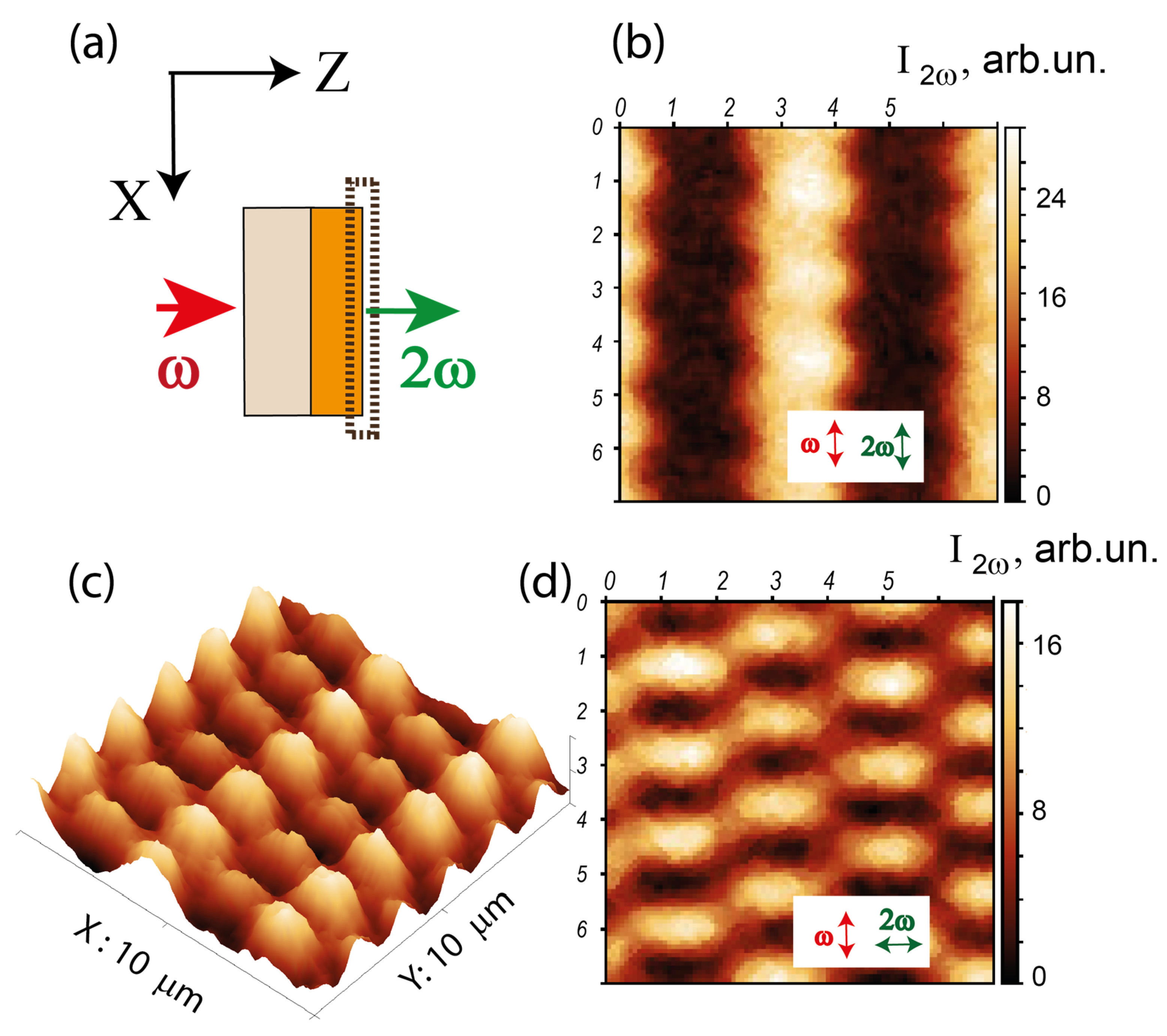
Similar conclusions were made based on the studies of the second harmonic generation microscopy of the
/air interface, as the pump laser beam at the wavelength of 850 nm was incident on the sample from the substrate side (see
Figure 2a). In that case, the SHG response at the wavelength of 425 nm is formed by the surface layer of 2–3 μm in thickness (determined by the escape length of the radiation at the SHG wavelength), which allows the study of the surface domain structure of garnet film at this hidden interface.
Figure 2b,d show the SHG intensity patterns for the parallel (panel
b) and orthogonal (panel
d) polarizations of the fundamental and SHG beams. In both cases the pump beam was polarized along the stripe domains oriented in the vertical direction on the Figure; the scanning was performed over the surface area of 7 μm × 7 μm. One can see that in the first case, the SHG pattern reveals the stripe domains that appear as the bands with a strong difference in the SHG intensity, while for the crossed polarizations of the pump and SHG waves, a chessboard-like pattern of the SHG intensity is attained.
Figure 2c shows the 3D distribution of the SHG intensity from the same surface region as in
Figure 2d. It also demonstrates a strongly periodic modulation of the nonlinear optical response with the periods of about 4.2 μm in the horizontal direction and corresponds to the stripe magnetic domains, while the period of 1.6 μm appears along the vertical direction. These images confirm the existence of zigzag-shape closure domains with a predominant in-plane orientation of magnetization, which stems from the symmetry analysis discussed in [
42]. Importantly, the stripe domains’ alignment and relevant SHG patterns are independent on the crystallographic orientation of the film and follow the direction of the external magnetic field used for their magnetization, which was removed prior to the MFM or nonlinear optical studies.
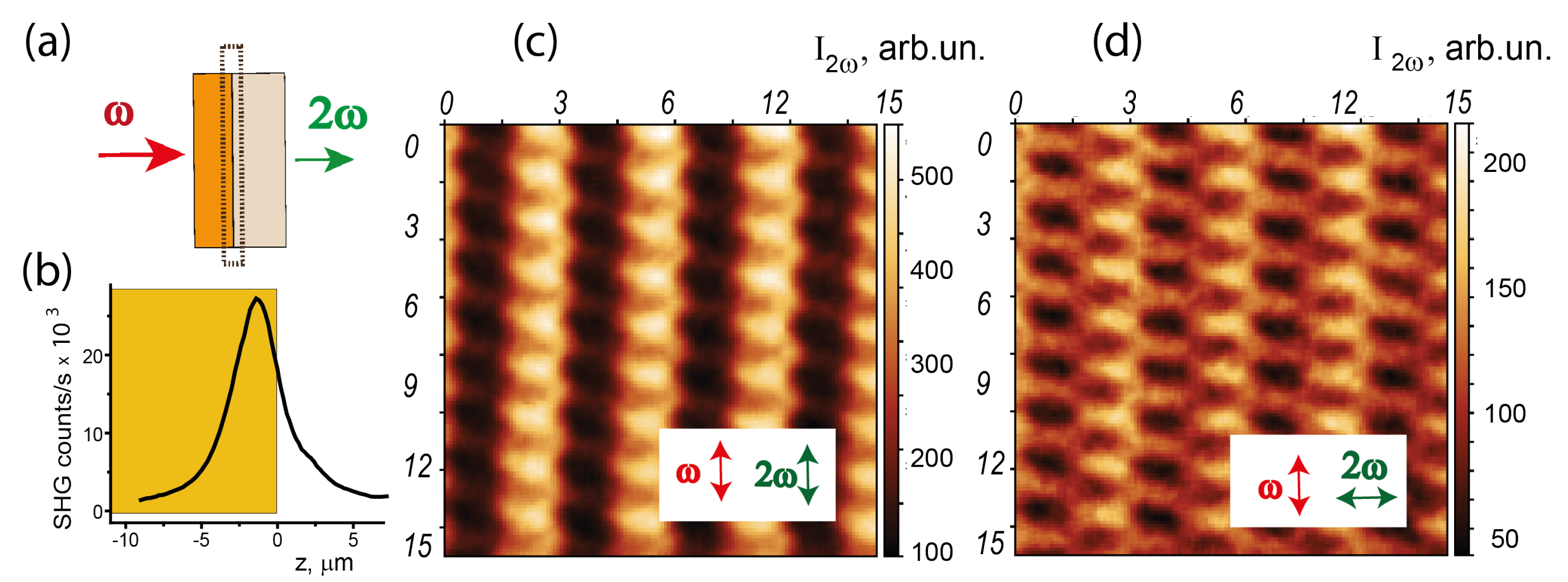
Similar SHG microscopy experiments were performed for the hidden
/GGG interface, which is inaccessible by the MFM technique (
Figure 3). Really, in that case the MFM probe is separated from the garnet layer by a GGG substrate that is several hundreds of micrometers in thickness. In order to attend the
/GGG interface by the SHG microscopy probe, we reversed the experimental geometry so that the laser beam was incident on the sample from the film side, as shown schematically in
Figure 3a. The effective thickness of the garnet layer participating in the SHG process was estimated by measuring the dependence of the SHG intensity on the coordinate along the normal to the film,
z, which is shown in
Figure 3b. One can see that the intensity of the SHG response reveals a maximum with the full width at half maximum (FWHM) of about ≈2.5 μm situated close to the interface. The coordinate of this SHG maximum
corresponds to the escape length of the SHG wavelength in the garnet films and thus determines the in-depth resolution of the SHG probe; its position was used as a reper when scanning along the
z-direction.
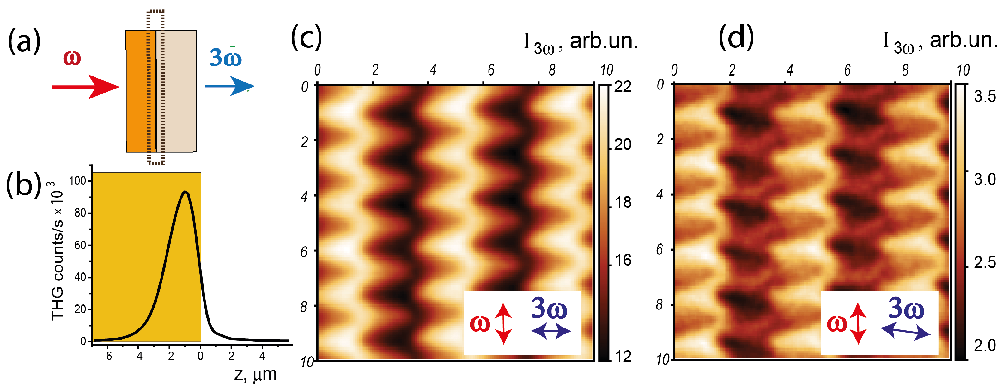
Similarly, we switched to the studies of the third harmonic microscopy of the garnet films.
Figure 4 shows the THG intensity patterns for the hidden
/GGG interface; the experimental scheme is sketched in
Figure 4a. The fundamental wavelength in the spectral range of 1200–1600 nm was used, so that the detected THG at 400–530 nm wavelength corresponds to the high absorption of the garnet film.
Figure 4b shows that the effective thickness of the layer contributing to the third harmonic generation is about 2 μm, which is less than for the case of the SHG scheme due to the higher-order nonlinearity of the process. Similarly, higher in-plane resolution of the THG probe is attained.
Contrary to the SHG case, the THG intensity pattern for the parallel polarizations of the fundamental and harmonic’s beams is constant within the experimental accuracy over the whole scanning range of 10 × 10 μm. This indicates that the relative value of the magnetization-induced components of the THG polarization are negligibly small as compared to the non-magnetic (crystallographic) ones. At the same time, if the detected THG polarization is close to the orthogonal position with respect to the polarization plane of the laser beam and forms the angle of 85
∘ (
Figure 4c) or 90
∘ (
Figure 4d) with it, pronounced THG patterns appear. One can see a zigzag-type dependence similar to that attained in the SHG response and very much similar to the MFM pattern shown in
Figure 1c. For crossed-pump and the THG waves’ polarizations, the domain structure demonstrates nearly triangular-like features places in a chess-like order above the stripe domains. If the analyzer is rotated by 5
∘ from the crossed position, an even more detailed magnetic pattern is observed, indicating the spatial resolution of the THG probe of less than 0.5 μm.
4. Discussion
For the case of noncentrosymmetric magnetic media, nonlinear polarization at the second or third harmonics’ wavelengths is given by a vector sum of the two types of terms of the electric field at the corresponding wavelengths, the so called
even and
odd components with respect to magnetization:
. In turn, these field components are determined by the effective
even and
odd components of the nonlinear susceptibilities
=
(− M) and
(M)=−
(−M), the latter changes its sign under the magnetization reversal. In this simplified description, we restrict ourselves linearly in
M terms of the magnetization-induced nonlinear optical response at the SHG or THG wavelengths, as they are the strongest in the case of a magnetized sample or in a medium with spontaneous magnetic structure (i.e., in a domain-like one) [
35]. Interference of these components of the harmonics’ fields provides linear in magnetization modulation of the SHG (THG) intensity, which can be characterized by the corresponding magnetic contrast
[
25] and allows the visualization of the magnetic domains with different orientation of the average magnetization. At this stage, magnetization-induced effects in the nonlinear optical response are qualitatively similar to their linear optical analogues, i.e., magnetooptical Kerr and Faraday effects, while the values of the SHG magnetic contrast
is typically one to two orders of magnitude larger.
Evidently, the contrast in the nonlinear optical response from different types of magnetic domains required for their imaging appears only if both
odd and
even in
M effective components of the nonlinear susceptibility exist. The sets of the nonzero components of the nonlinear susceptibility tensors are governed by the crystallographic and magnetic symmetry of a medium. As garnet belongs to the centrosymmetric cubic (
-symmetric) class, the bulky SHG is suppressed by symmetry arguments and thus the second harmonic (in the electric dipole approximation) should be generated by the interfaces with broken inversion symmetry. At the same time, the bulk SHG effect was registered in substituted garnets with the structure distorted by the presence of large ions such as bismuth or induced by the lattice mismatch at the garnet/GGG interface [
43], which seems to be our case. Meanwhile, third harmonic generation is allowed in the bulk of the materials of any symmetry class, including garnets.
If taking into consideration the transparency of garnet films at the fundamental wavelength, transmission coefficients at the second and third harmonic’s wavelengths and localization of the pump beam in the laser beam waist, the intensity of the SHG (THG) transmitted through the garnet film can be expressed as
where
2, 3 corresponds to the number of harmonic (second or third),
is the dependence of the fundamental field intensity on the transversal radius-vector
and on the coordinate along the direction of the beam propagation,
z. Integration over
z can be restricted by the waist length according to the expression
, where
is the Rayleigh length of the focusing objective and
d is the film’s thickness,
is the input intensity of the fundamental laser beam,
are the intensity transmission functions at the SHG and THG wavelengths, and the integral is taken over the excited volume
V of the
film. Here we assume that the effective nonlinear susceptibilities
are uniformly distributed in the garnet film and the nonlinear contribution of the GGG substrate is negligibly small, as stems from our experiments. Thus the SHG or THG intensity maxima of the
dependencies (see
Figure 3b and
Figure 4b) are attained within the garnet film close to its exit boundary. It is worth noting that the resolution of the THG microscopy technique is higher as compared to the SHG one due to the third-order dependence of its intensity on
, while it is quadratic for the SHG case.
The analysis of the SHG and THG intensity patterns shown in
Figure 3 and
Figure 4 is a complicated task, as the epitaxial garnet films are (111) symmetric and the tensors
and
contain many nonzero components, both crystallographic (
even) and magnetization-induced (
odd) [
35,
44]. Still, based on the analysis of the SHG intensity patterns measured for the parallel (
Figure 2b and
Figure 3c) and orthogonal (
Figure 2d and
Figure 3d) combinations of polarization of the fundamental and SHG beams, one can judge the orientation of the magnetization in domains similarly to those discussed recently in [
42] for the garnet/air interface. Namely, the method reveals only the in-plane M components orthogonal to the polarization of the SHG wave, i.e., “vertical” in the first case and “horizontal” in the second. It means that the spontaneous magnetization of stripe domains of the garnet film is tilted with respect to the film’s normal, which may be due to the (111) film’s symmetry. Similar conclusion on the direction of the magnetization in such films has been proposed based on the analysis of the MFM image of the cleavage (end face) of the garnet film [
42]. This provides a large (up to 60%) contrast in the second harmonic intensity generated by the neighbour stripe domains.
Shorter-period modulation of the SHG intensity in the direction along the stripe domains observed at the interfaces of the
layer with air (
Figure 2) and with the GGG substrate (
Figure 3) is associated with the nonlinear response of the block (closure) domains; the modulation is better seen for the crossed polarizations of the SHG and pump radiation (panels
d in
Figure 2 and
Figure 3). In that case, the maximum contrast of the SHG intensity is attained for the adjacent closure domains placed along the horizontal line in
Figure 2d or
Figure 3d, which correspond to the opposite signs of the “vertical”
M component. If taking into account the analogous analysis of the SHG intensity pattern for the parallel polarizations of the SHG and pump beams, we have to conclude that the in-plane magnetization of the closure domains forms a nonzero angle with the magnetic stripes. This is probably the reason for the formation of the zigzag-shape patterns attained both in the MFM measurements (see
Figure 1c) and in the THG response (
Figure 4).
Based on the results of the experiments described in this paper, we may conclude that the organization of magnetic domains at the hidden /GGG interface is quite similar to that of the /air interface; even the periods of stripe and block domains nearly coincide. This shows that a discontinuity of the garnet crystalline structure plays the most important role in the formation of the closure surface magnetic domains, while the influence of the surrounding media, namely crystalline gallium gadolinium garnet or air in our case, is less important.
5. Conclusions
Summing up, we performed experimental studies of the magnetic domain structure of 10 μm thick -substituted epitaxial garnet films by a combination of magnetic force microscopy and nonlinear optical microscopy techniques based on the effects of the second and third harmonics generation. In the latter case, strong localization of the pump radiation of a pulsed femtosecond laser source along with the nonlinear power dependence of the registered harmonics’ signal allowed to the visualization of the magnetic stripe domains in the bulk of the garnet film through a pronounced contrast in the average second and third harmonics’ intensity in adjacent domains. Based on the symmetry analysis of the nonlinear optical response, we conclude that magnetization of this type of domain is tilted with respect to the film’s normal as well as to the stripe domains.
Moreover, we applied the nonlinear optical technique to approach and investigate the magnetic organization of the buried interface of the epitaxial layer with the gallium gadolinium garnet substrate, which is inaccessible for the MFM studies. We found that a zigzag-shape interface domain appear above the bulk stripe ones, similarly to the upper /air interface studied quite recently. This confirms that the main role is played here by the discontinuity of the garnet crystalline structure for the magnetic domains’ organization, while the type of neighbour medium is less important.
We also present the first experimental demonstration of the efficiency of the the third harmonic generation microscopy for the study of magnetic domains in garnet films. In spite of relatively small linear values in magnetization contribution to the third harmonic response, the THG microscopy for the nearly crossed polarizations of the fundamental and THG beams allows the visualization of the surface magnetic closure domains at the hidden garnet/GGG interface and provides even higher spatial resolution of the magnetic structure as compared to magnetization-induced second harmonic generation.


