1. Introduction
Recently, the application of UAVs (unmanned aerial vehicles) has been widely launched in distinct markets. According to a report about market forces, the revenue that comes from the wide application of UAVs is expected to exceed USD 8.5 billion by 2027. Additionally, UAV-based architectures have been explored for the development and implementation of next-generation technologies such as 5G, V2X (vehicle-to-everything) communications, etc. [
1]. Such technologies have been applied in the industrial, agriculture, transportation, and entertainment fields, and even in the current war. The application of UAVs has gradually become a core research theme in environmental detection, and the research of aerial vehicles is most popular with aerial QA (quadrotor aircraft). Moreover, the study in [
2] aimed to optimize the autonomous performance (i.e., both longitudinal and lateral) and endurance of the quadrotor-type aerial vehicle simultaneously, depending on the autopilot gain coefficients and battery weight. In [
3], the authors explain that the purpose of their research was to investigate the impacts of UV (ultrasonic vibration) and tool-pin profiles on the mechanical properties and microstructural behavior of AA7075-T651 and AA6061-T6 joints. The reason that quadcopter aircraft can obtain a balance between two vehicles is due to the flight principle and materials cost. The quadcopter performs altitude calculations based on the sensors configured on the flight controller. Moreover, it is calculated by a three-axis gyroscope and a three-axis accelerometer to achieve directional monitoring of various data (e.g., angular rate, acceleration, etc.) of the quadcopter. However, there have been many critical issues, including hardware and software, which could be addressed in the deployment of the UAV. The study in [
4] investigated viscous cementitious mortars for AAM (aerial additive manufacturing); it also assessed workability and buildability. A robotic arm representing UAV movement in three-dimensional space moved a lightweight deposition device to extrude multiple layers. In fact, the discussion of the PID (proportional–integral–derivative) algorithm for precisely and accurately controlling the UAV was an important research event. The PID algorithm can more effectively improve the speed control of these types of motors. Based on the previously described facts and the experimental function, we were motivated to provide a self-making and self-designing version of the PID controller. Finally, the study underwent some manual tests that support a determination of the efficacy of an in-depth controller with a PID regulator plus a direction controller equipped with an Stm
® MCU (micro control unit) modular. The main objective, and effective target, was to achieve satisfactory control performance compared to other controllers. Seriously speaking, there are many existing works describing studies that were carried out that arrived at relevant results from the experimental simulation of UAVs. In report [
5], authors describe in-depth research based on a quadcopter UAV model that is widely used in society, including for agricultural pesticide-spraying UAVs and defense-industry detection UAVs. Moreover, the important architecture of this UAV includes a flight controller, electronic governor, and motor. Quadcopter UAVs need to be lightweight and maneuverable, as these characteristics are advantageous [
6]. Hence, the motor selected was a brushless DC motor. Compared to a brushed DC motor, the brushless DC is superior, although the cost is higher, because the brush introduces friction with the rotor inside. On the other hand, the produced sparks could result in increased maintenance costs [
7]. The literature detailing the PID controller of brushless DC motors is described to help this study on the characteristics of brushless DC motors. The motor needs to convert DC into a three-phase alternating current and promote the permanent magnet in the motor structure and the stator for angle commutation. Furthermore, it needs to be energized in order, as far as the rotational moment is generated. Paper [
8] proposed a concept called electron commutation, that is, a circuit of the electronic governor, realized according to the electronic commutation, adjusts the speed and direction of the motor in real time according to a change in the control signal. According to the paper discussed above, the quadcopter UAV needs not only have four brushless DC motors, but also four electronic governors. Certainly, the control center is responsible for integration, that is, the flight controller is based on the work of [
8] using Stm32F407VGT6 for flight-controller development. In addition, the MCU uses an ARM-M4 processor, and the main frequency can reach up to 168 MHz. The single-chip system has high performance, which is suitable as a flight chip, and this component is similar to our human brain. Besides, it is responsible for each foreign message and signal action for the quadcopter UAV flight controller.
In fact, the MCU is required to be equipped with a gyroscope and an accelerometer, and to use the data from these sensors to determine the angular velocity of the UAV. The law of conservation of angular momentum can be evaluated according to the obtained data when the vehicle is subjected to external forces. If the angular momentum changes, the total angular momentum will not change in any way under such conditions. This concept can be applied to UAV aircraft. In report [
9], the gyroscope and accelerometer use MPU6050 components to measure the angle and angular velocity of this UAV. From the pieces of knowledge according to the above description, one can calculate the external force on the UAV by measuring the angle and angular velocity of the UAV [
10,
11]. It could also follow up on the IMU (inertial measurement unit system) to know the error value of this application product. It is convenient to compare the error value with the target value, and let the quadcopter UAV compare this error value. The action of correcting the PID controller is an important indicator of the feedback system, through this value back to the input.
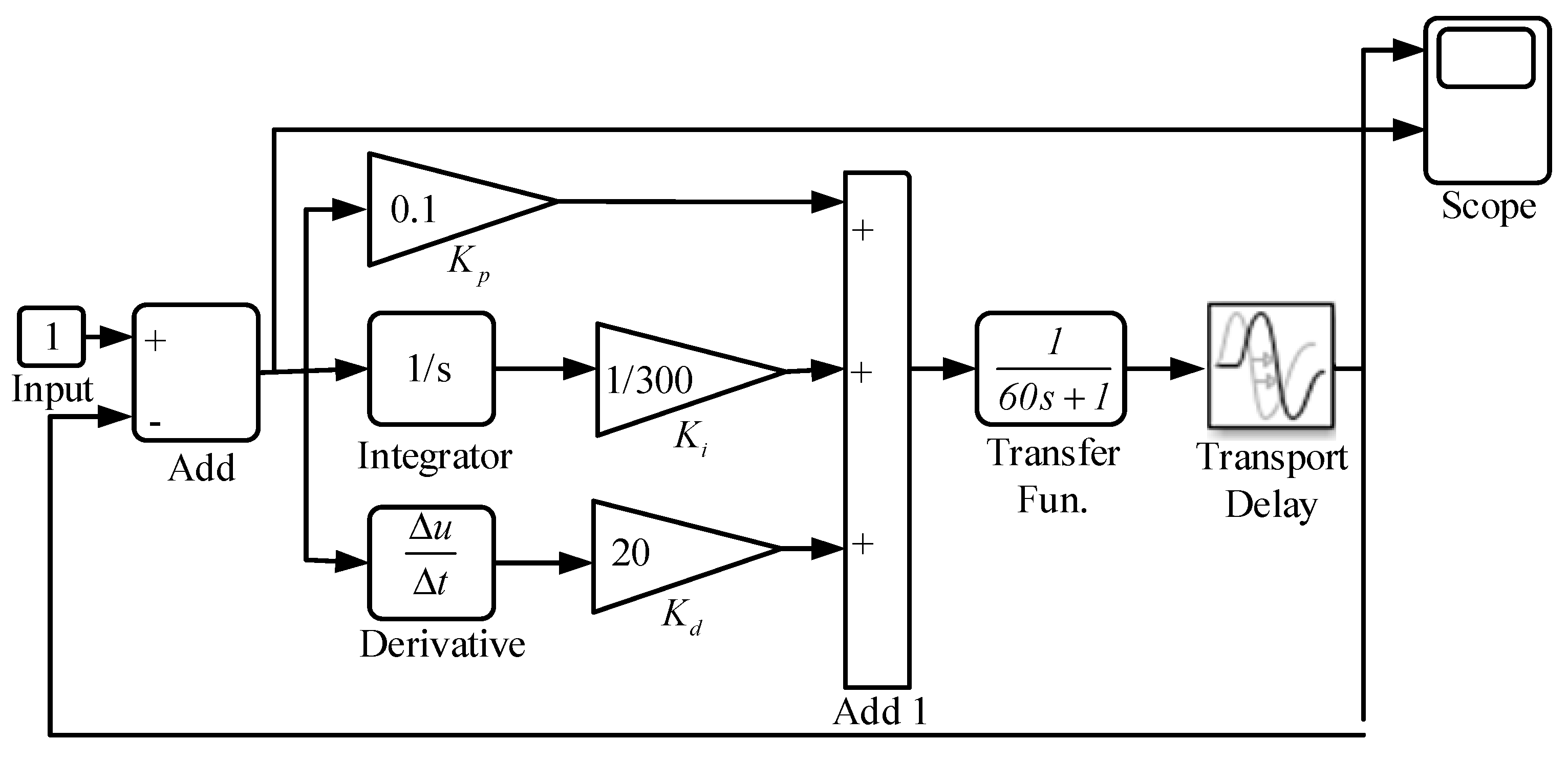
The current article proposed a basic Optimized PID architecture shown in
Figure 1, which runs the tool Simulink in Matlab
@, and is designed by the first-order differential equation. Such an equation can be used to verify the PID control algorithm and to eliminate the error, for example,
,
, and,
. Accordingly, it is worth knowing that the above-mentioned parameters of
,
, and
could be adaptively adjusted by following up with the UAV location. Typically, the order of the control steps is first to adjust the proportional value
which is followed by the integral stage
modification, and the correction of the derivative parameter
will be carried out in the end, if necessary.
Therefore, the proposed algorithms of the PID controller can be declared to have optimized performance, which can be noted as the main contributions of the investigation. For this reason, the commonly used and powerful PID control concept is used to filter the transformed error variables, that is, to optimize the performance of a UAV. A composite learning algorithm consisting of a neural network and a perturbation observer is incorporated to handle the error-induced nonlinear terms as the flight safety progresses [
12]. A successful solution for eliminating path deviation in multi-terrain robots has been proposed and implemented in [
13]. The deviation is almost negligible after the implementation of the proposed algorithm, and it provides fusing wheel encoder and inertial measuring unit (IMU) data for PID control using the ROS (robot operating system) packages. The work in [
14] proposed an NLPID (nonlinear PID) controller to stabilize the translational and rotational motion of a 6-DOF (degree of freedom) UAV quadrotor system and force it to track a given trajectory with minimum energy and error, except in the previous discussion of the PID controller which has the three parameters that can be adjusted according to the MPU6050 return angular speed and rate [
15].
Generally, the motor speed is controlled by the PID controller in order to ensure that the quadcopter UAV PID is stably controlled. In [
16], where the use of Ziegler–Nichols oscillation tuning rules is described, the use of closed-loop testing to obtain critical point information that is needed to determine the PID controller is detailed. The work presented in [
17] illustrates a quadcopter equipped with PID controllers for stabilization requirements and that are used to regulate its four basic motions: roll, pitch, yaw angles, and altitude. The quadcopter was originally equipped with sensors and software to estimate and control the orientation of the quadcopter. In addition, an APE (adaptive perturbation estimator) was based on a DSC (dynamic sliding control) applying the PID for a UAV, as demonstrated in [
18]. The presented controller is used to significantly remove the negative effects of uncertainties/perturbations to improve the stabilization control performance of a UAV.
In general, the basis of the PID controller is ultimately defined by a feedback system. However, due to the non-linear and physical parameters of multi-rotor UAVs, the attitude control system of the UAV will be designed as a cascade structure of PID control. In general, the controller consists of three attitude angles; these are Yaw (YAW), Pitch (PITCH), Roll (ROLL), which are arranged on the
X,
Y, and
Z axis, respectively. The
Z-axis of the fuselage is surrounded, and the attitude control is the basis of the quadrotor UAV PID control method. The basic knowledge of cascade PID is supplemented to facilitate future design. A multi-rotor UAV simulation model created in Matlab
@Simulink that presented the results of the first stage is discussed in [
19]. In the previous report, a quadcopter mechanical model was developed based on Simscape Multibody library elements. In addition, an angular position and flight altitude control model based on PID controllers was designed using the standard Simulink libraries.
It is assumed that stability, controllability, and even causality are normally the critical conditions of a control system. On the other hand, based on the constrains that motivated the investigation of the quadcopter and the data readings of the sensor analyzed by the IMU, the overall results obtained follow the methodologies proposed in this article. Recently, the PID is not efficient as mentioned by many other studies, such as in the discussion articles [
20,
21,
22], when the environment faces external disturbances and parametric variations. However, the scenario considered in the current article points out that the use of PID was focused on the practice experiment without too much mathematical analysis. That is, the motivation for the proposed “optimized PID” is to try to give contributions on the following points:
Try to obtain the most stable conditions of the UAV by adjusting the four parameters, kP, ki, kd, of a PID controller.
Trying to obtain the best results from a PID controller that can implicitly control the roll, pitch, and the yaw of a quadrotor.
Attempt to implement the proposed “optimized PID” with some experimental tools (Proteus®, Matlab/Simulink®, and MCU IDE) for validating the obtained results. It is believed that these results from the experimental simulation will be of interest to beginners (even senior scientists) in terms of stability and control for a PID controller.
The use of devices with data-driven edge computing concepts has been discussed in the proposed methodologies. It is believed that edge computing techniques will become the main trend for embedded technologies in UAVs, even a 6-DOF UAV Quadrotor.
Then, the contribution of the article aims at firstly the angular velocity and acceleration data read by the Stm
® development board embedded with an MPU6050 [
23], and the altitude at which the measurement instrument platform is located by the MS5611 barometric pressure and temperature sensor. Then, in the edge device, a brushless DC motor attached to the Stm
® controller is adapted to 4 PWM (pulse-width modulation) signals via the output port. To control the brushless DC motor, an off-the-shelf BLDC (brushless DC) motor is assigned as a transmitter to the electronic controller.
The rest of this paper is organized into five sections, which are described as follows. After the introductory section, the methodologies including hardware and software employed in the UAV are discussed in
Section 2. The detailed implementation of the relevant techniques and the progress and results are presented in
Section 3 and
Section 4, respectively. Finally, a brief conclusion is given in
Section 4.
3. Implementation of the Relevant Techniques
The comprehensive review in [
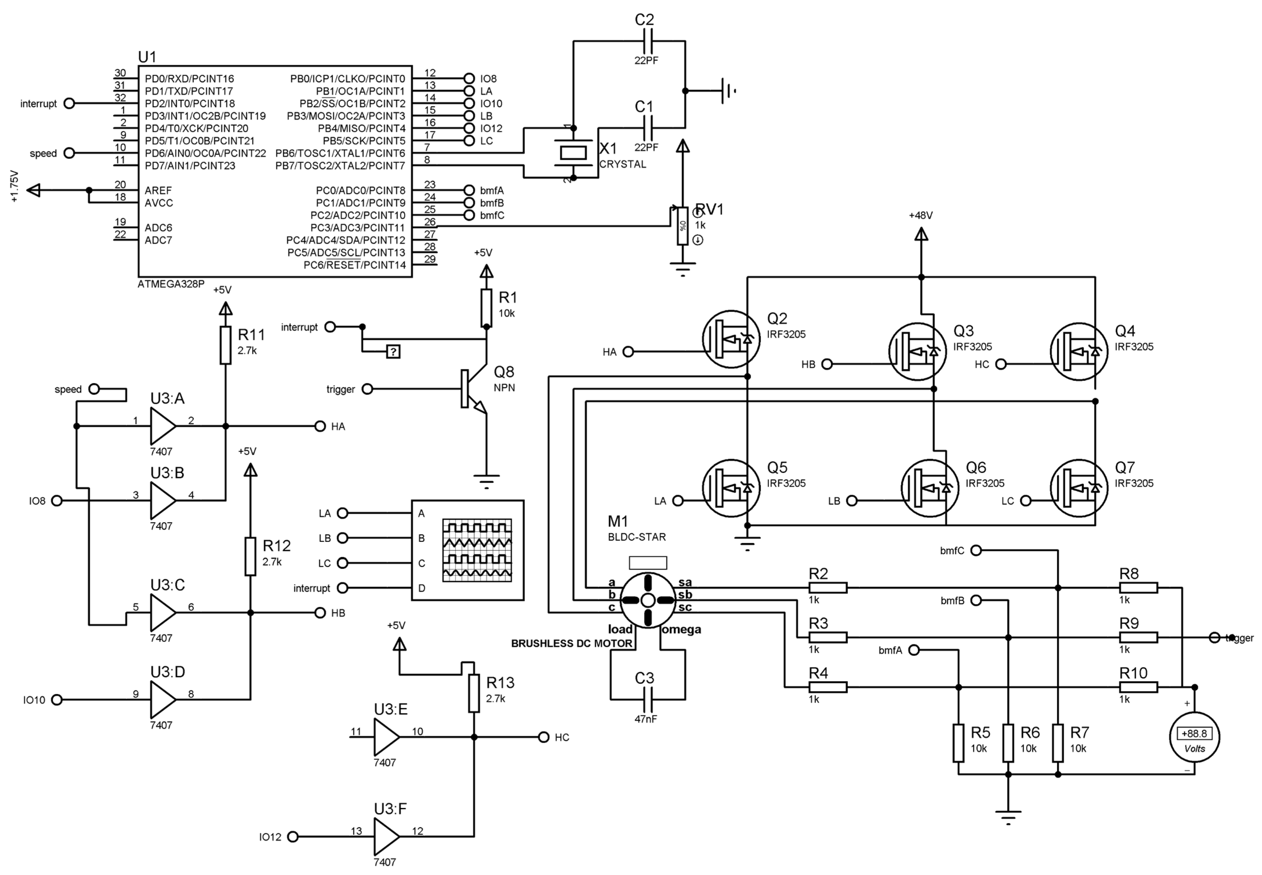
16] provides the state-of-the-art embedded sensors, communication technologies, computing platforms, and machine learning techniques used in autonomous UAVs. Based on the existing program and hardware circuit of the electronic governor shown in
Figure 2, the hardware-related circuit is shown in
Figure 4. The circuit is output by the ATMega328P MCU for three-phase PWM, the single chip will be interrupted by the two pins, the pins are officially defined as a priority, the 32th pin of this circuit diagram represents the two pins, this pin is used in the rotation position of the induction motor, and the 12, 14, and 16 pins of the circuit diagram are input to the high level, and 13, 15, and 17 are low. The speed pin is PWM output, and the 26 pin is PWM The input pin passes the high potential signal to the IC with the serial number 7407, and in order not to burn the MCU, such a triode gate is used to convert the level, and this schematic is called IRF3205 [
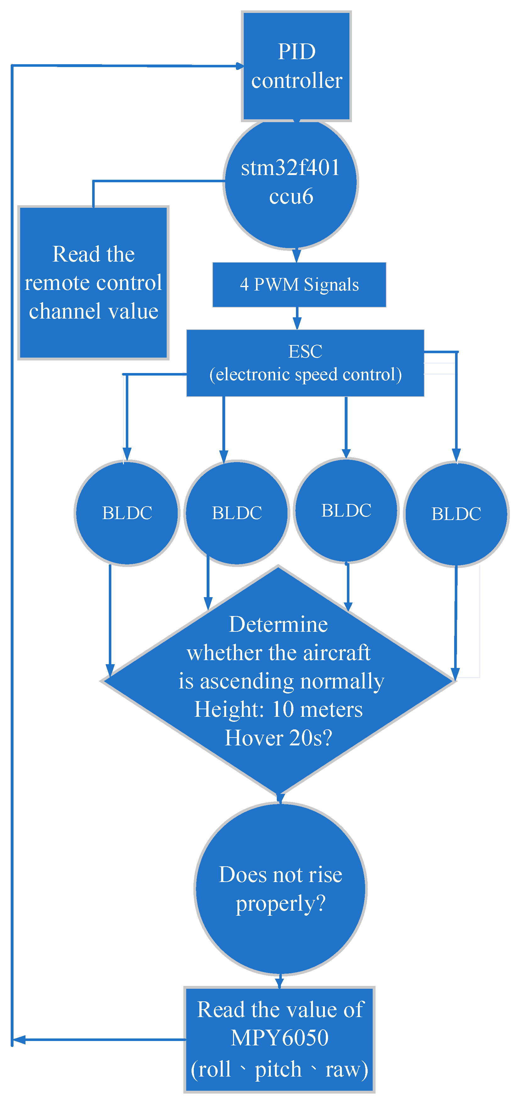
29]. This device is an N-channel MOSFET, and the voltage at its output pin is controlled by the ATMega328P MOSFET. The switching state provides enough current and voltage to drive the motor, and the low on-resistance of the IRF3205 component also reduces motor noise and interference, allowing the motor to rotate stably. The road PWM signal is followed by the electronic governor, and it will not only read the PWM signal value but also write into the generation of electronic commutation and inform the brushless DC motor. Thus, the motor generates angular commutation and then lets the motor carry out speed-regulation action. However, at present, the ascent principle of the quadrotor UAV is based on the motor to drive the propeller rotation, and then the air resistance produces a downward reaction force. This reaction force is going to generate four different directions of rotation for the embedded motors. On the other hand, two pairs of motors rotate in opposite directions, respectively. The top-right and bottom-right motors are marked with No. 1, and No. 2, and the upper-left and lower-right motors are called No. 3 and No. 4, respectively. Motors No. 1 and No. 2 rotate counterclockwise, and motors No. 3 and No. 4 rotate clockwise to achieve the ascending flight principle of a quadcopter UAV. Specifically, the control system uses a commercial version of the remote control. Since this version of the remote control is more mature and the control of the drone has a certain danger, using a remote control with a more stable signal is necessary. The Stm32f401ccu6 modular uses the Read channel function to read the specified channel of the receiver. Once the command has been received, the function is converted to the given range according to the number of the specified channel. The channel is initialized when it is closed and maintains the stability of the channel output PWM signal. The channels of the receiver are the first channel that presents the mean of the “aileron” used to control the roll axis of the quadcopter. This command is received by the Stm32f401ccu6 modular and the lateral movement control signal of the right stick of the remote control. In addition, the second channel is the lifting channel; although this term and the throttle channel conflict, their essential concept is different. That is, the pitch axis is in the form of the pitch axis as in the definition of the quadcopter. The pitch axis is the axis that rotates back and forth around the ride when the quadcopter UAV performs a lifting motion.
Normally, to keep the speed of the left and right rotor propellers unchanged, the speed of the front rotor propeller can be reduced. It is also possible to increase the speed of the rear propeller. The two methods suggested above can be used simultaneously. Anyway, the aforementioned statement is also applied to the pitch motion. The simulation of the basic PID operation is carried out in the tool Proteus
® Ver. 8.9 [
30], which provides all the components used in the circuit used. In the following, the description to the fact of the action used the methods of “trial and error” is necessary, because most of the simulation is implemented practically. However, there is an oscilloscope equipped to measure the real-time signals between the transmitter and the receiver embedded in the controller based on the Stm
® MCU.
The third channel is the throttle channel which is the key to the vertical flight control of the quadcopter UAV. As the name suggests, it is used to increase or decrease the speed of the four brushless DC motors simultaneously. Accordingly, the lift generated by the four rotors could make the body rise or fall. Therefore, to achieve climbing or falling, the fourth channel is proposed to be subjected to the steering gear. The principle of the fourth channel is able to overcome the influence of the reverse torque. In general, two of the four rotor propellers rotate clockwise and the other two rotate counterclockwise. The two diagonal propellers on the diagonal rotate in the same direction. Following the experimental motivation, this paper uses the remote control to control four brushless DC motors simultaneously through the Stm® modular with Stm32f401ccu6, in adjusting the balance of the retort, hovering, and other phenomena by the PID controller.
4. Detailed Discussions and Results
The discussion of the implementation of the proposed improved PID methods is going to be described in this section. In addition, the full hardware skeleton is also introduced. The results of the simulation are also presented.
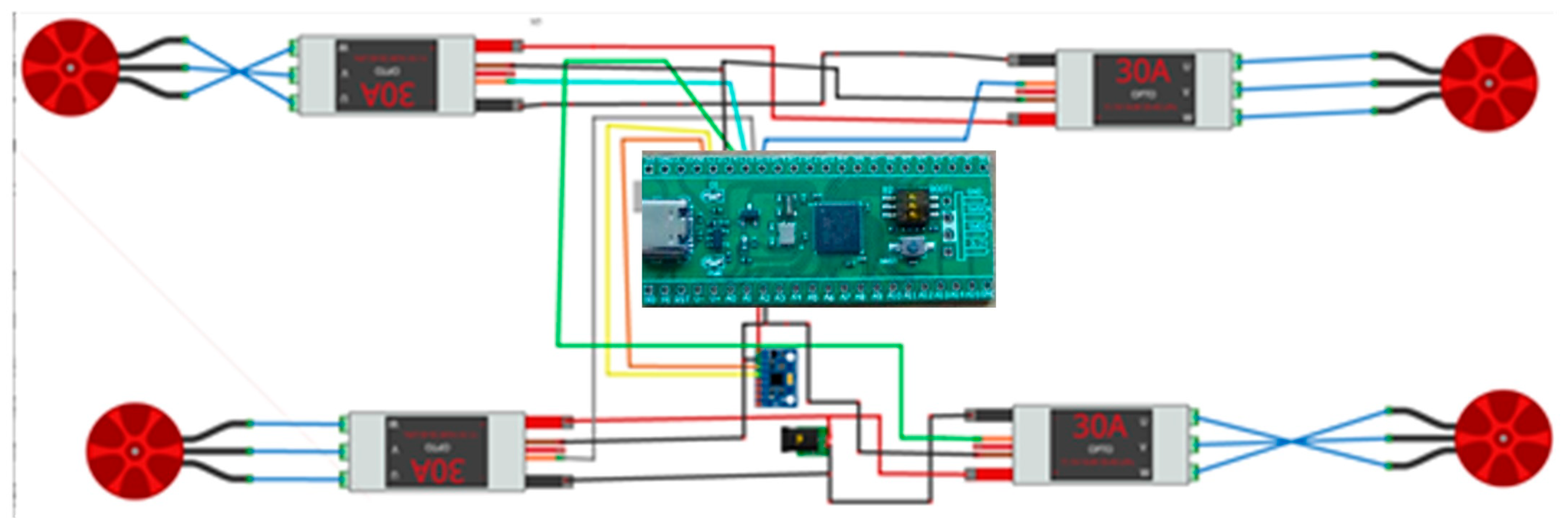
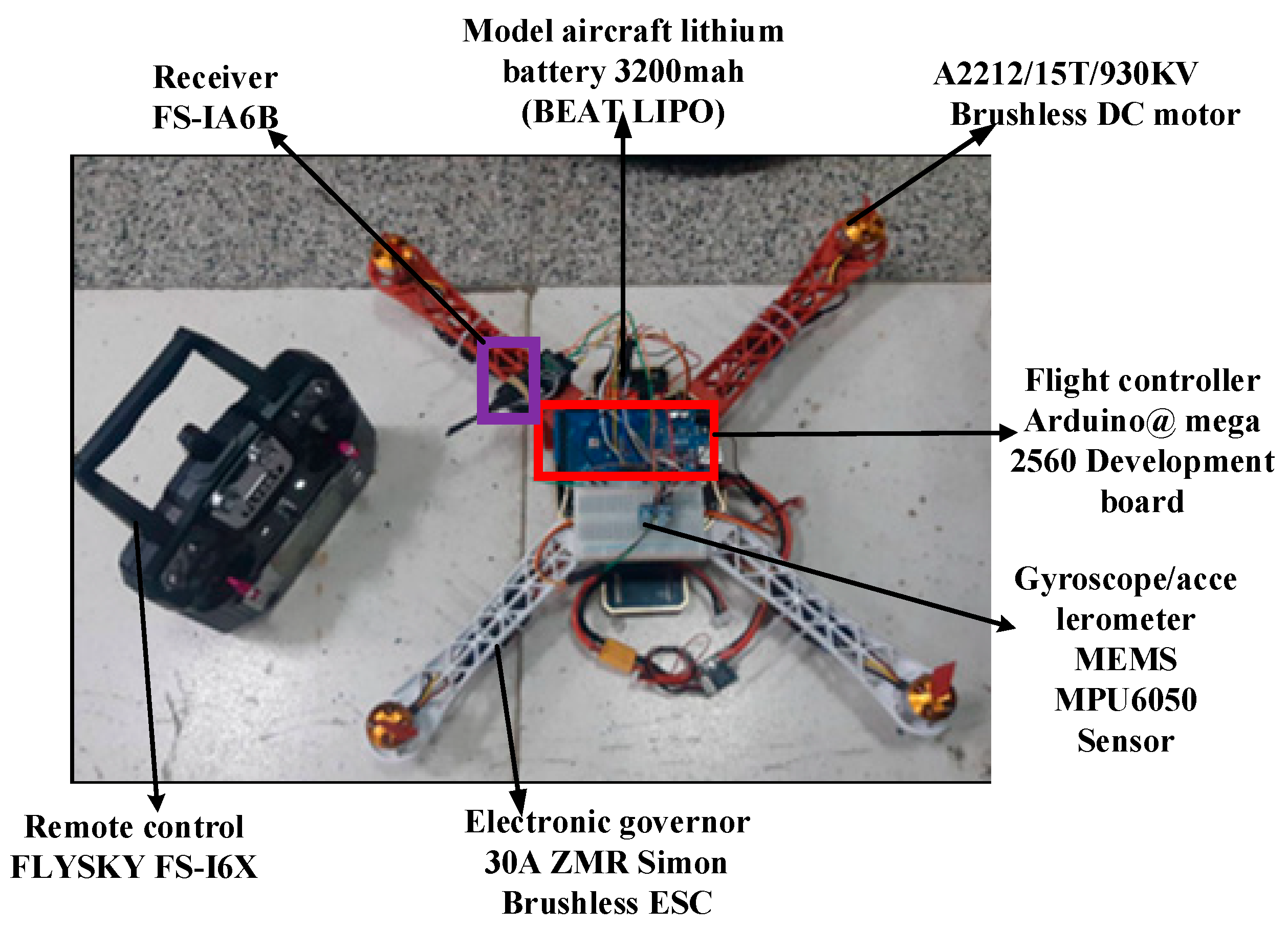
As shown in
Figure 5, which includes six main hardware parts for the hardware skeleton of the developed UAV, there is a receiver with #FS-IA6B, a battery with 3200 mah BETA LIPO, four brushless DC motors with A2212/15T/930KV, a flight controller with Stm32f401ccu6, a gyroscope/accelerometer with MEMS MPU6050 sensor, and an electronic governor with 30A ZMR, and so on. Hence, the configuration of the UAV is organized by the above-mentioned parts plus a remote control referred to as FLYSKY-16X.
In this article, the Java code developed is uploaded to the Stm32f401ccu6 development platform. The data are simulated using Matlab
®/Simulink for wave patterns, and the Serial Receive module is deployed to receive the simulated code [
31]. As the statement has been announced in the introductory section, the PID architecture proposed in
Figure 5 in fact has a linear behavior of the PID. However, the outcomes from the simulation have actually revealed that the proposed method has good performance in terms of accuracy, robustness, finite time convergence, and the robustness of flight activity when it is compared with other PID structure [
32]. The previously mentioned proposed PID performance can be proved with the results which were obtained later.
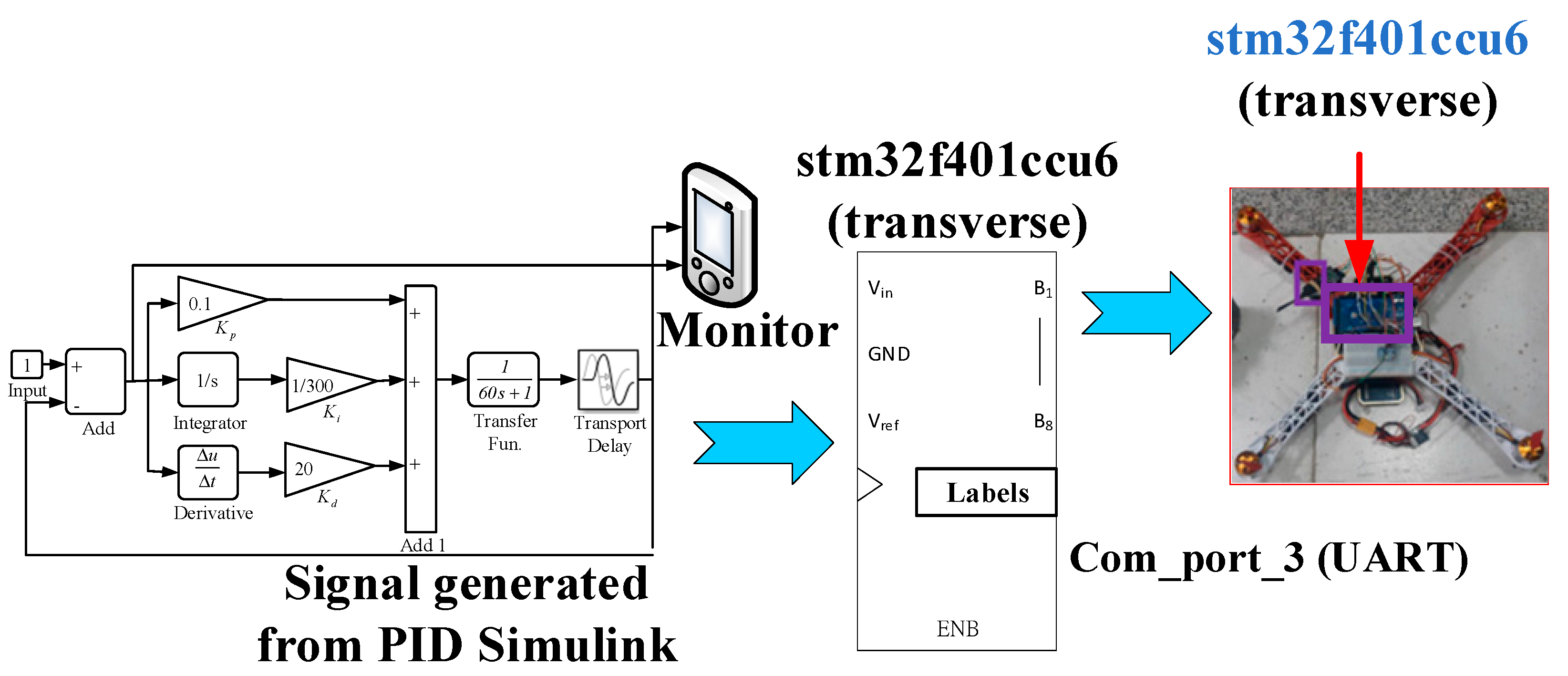
The connection diagram for the overall system flow of PID to control a quadrotor UAV is shown in
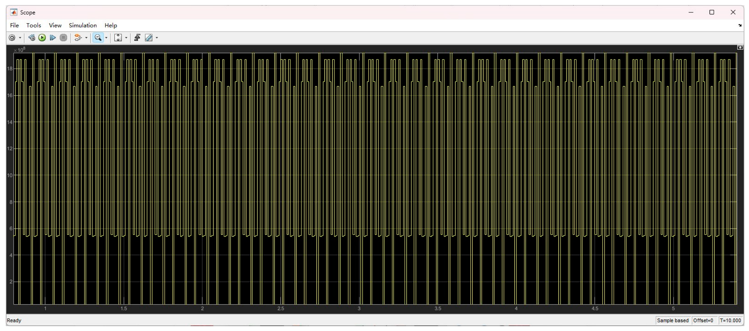
Figure 6. The waveform type uses an integer of 32 bytes, and the flight controller outputs a PWM data response signal, as shown in
Figure 7. This module receives the remote control signal from the flight controller to send the PWM signal. It is obvious that the stability of the generated PWM signals is well achieved for the PID controller. That is, the previous statement could be explained by the phenomena that occur on the
X axis and
Y axis, which represent the scales of amplitude and time, respectively. The amplitude always occurs as approximately 10
18 during the duration of 0 to 5 s, and can remain in a stable state for a long time. The above fact has verified the optimized PID’s functionality.
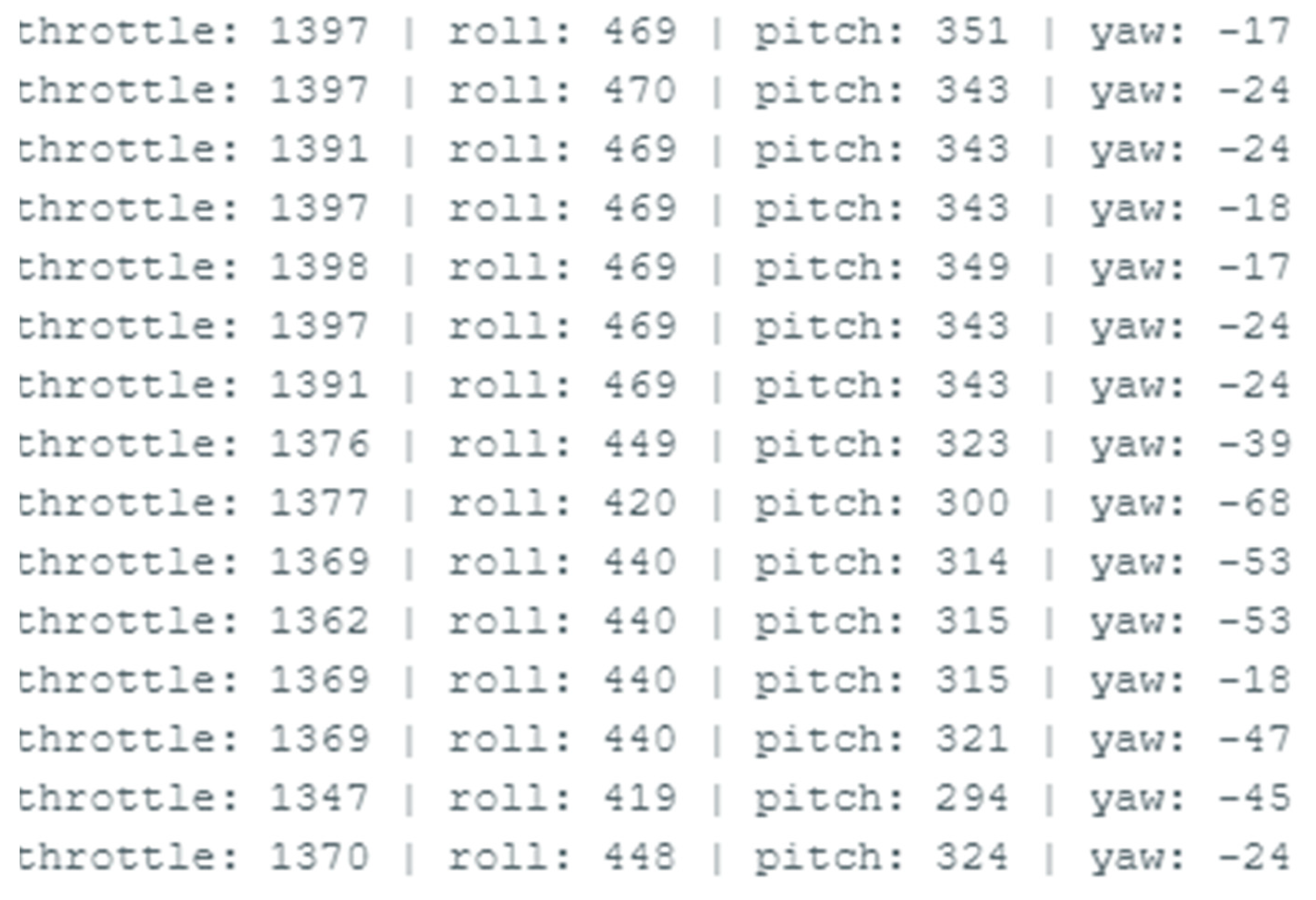
Moreover, the simulation of the motor speed response waveform of the Stm
® Stm32f401ccu6 is also evaluated. In the deployment, the three online measured degrees, YAW, PITCH, and ROLL, are monitored by the Stm32f401ccu6 as the block shown in
Figure 6. In the surveillant system, these three values are calculated and shown in
Figure 8. For example, the roll, pitch, and yaw are displayed as “1370”, “448” and “-24”, respectively. The “positive” and “negative” values illustrated in
Figure 8 could correspond to indicate the “forward” and “reverse” directions. The data are helpful in the process of designing the PID controller in the future. On the other hand, the data are useful for recognizing that the quadrotor UAV can be operated under normal control. At the same time, the UAV could arrive at the correct local position and flight direction according to the message shown in
Figure 8, which was sent back to the control center.
Certainly, it is worth trying to compare the response outputs via a PWM signal generated by the proposed PID controller with the other techniques discussed in [
15]. Seriously, the PWN signals are generated in a firmly fixed way, as shown in
Figure 7, which means that there is no doubt that the PWM signal is always kept stable from the starting point of the flight controller to the end. Accordingly, the PWM signals generated from the so-called “optimized PID” controller can cause the UAV to operate and work rigidly. Thus, the aforementioned fact has consistently outperformed the performance shown in article [
15]. Moreover, the three parameters, which include
,
, and
, are relevant to a PID controller. The comparative item defined as “rise time” occurs at different scenarios of the PID models which are divided as PID-1, PID-2, and PID-3. The comparative results are demonstrated in
Table 2 where the three parameters of
are assumed as
,
, and
, respectively. Finally, it is obvious to understand that the “Rise time” of the three different PID models can be adjusted and obtained as corresponding to values of 0.0180, 0.0180, and 0.0352 s. Actually, in
Table 2, the “rise time” generated from the proposed “Optimized PID” with three different PID models is compared with the outcomes from article [
15].
Eventually, the validation of the performance evaluated on the proposed optimized PID could be certified with quantification. A feasible first-order continuous system with time delay and the transfer function of
is applied to the explain the behavior for the proposed optimized PID shown in
Figure 1. The characteristic equation can be calculated by making the denominator expressed in the transfer function equal to zero, that is,
. According to the previous discussion, the PID can mainly provide feedback on the changing signal depending on the error values measured from the output of the controller. Typically, the order of the control steps is as follows: adjust the
value, then the
factor, and finally the parameter of
.
There are 12 figures included in
Table 3 where the simulation of the optimal PID controller proposed in this article is carried out by adjusting different PID parameter values. In order to limit the size of the text, only some of the plots obtained in the simulation section will be explained in this article. For example, in graph (a) shown in
Table 3, the yellow and green curves denote the control signal as “after PID regulation” and “without PID regulation”, respectively. It is clear to see that the stability of the controller can be quickly researched under conditions without
values. On the other hand, the speed of stability for a PID controller is definitely not dominated by the value of
. Additionally, plot (c) shown in
Table 3 tells that
should decrease since the larger value of
will lead to divergence of the control signal.


