

Progress in Lightweight Design Methods for Large-Size Panel Structures in Manned Pressurized Capsules

Abstract
:1. Introduction
2. Overview of Pressurized Capsule Structure
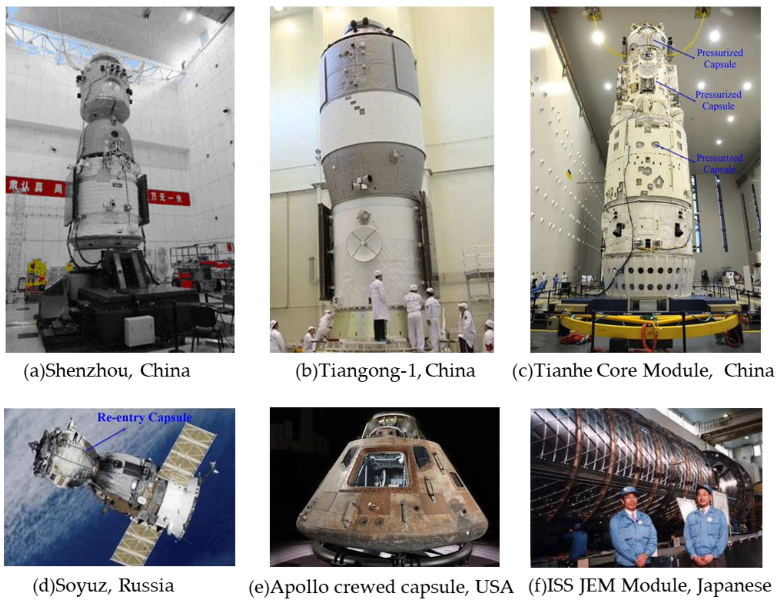
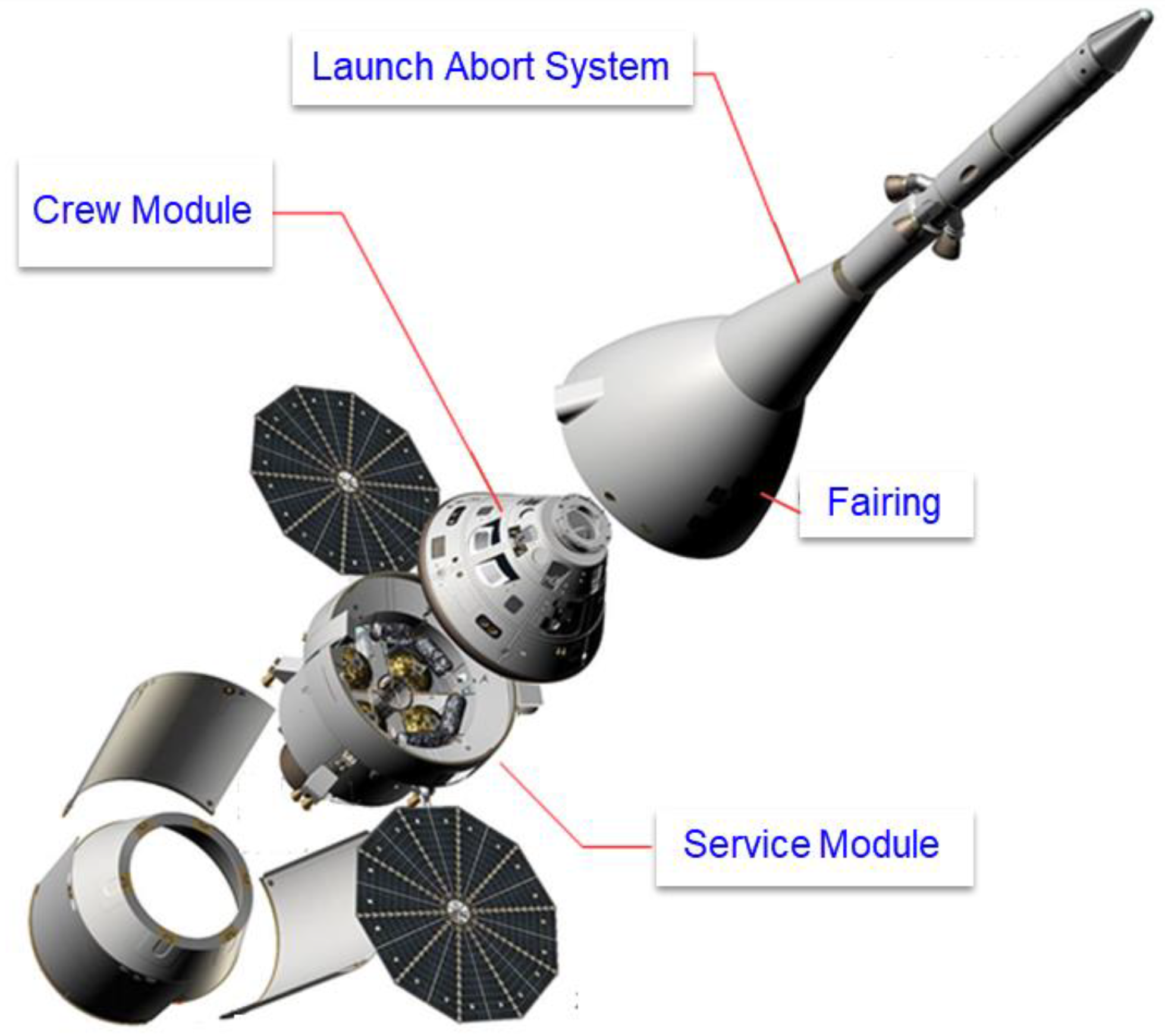
2.1. Pressurized Capsule
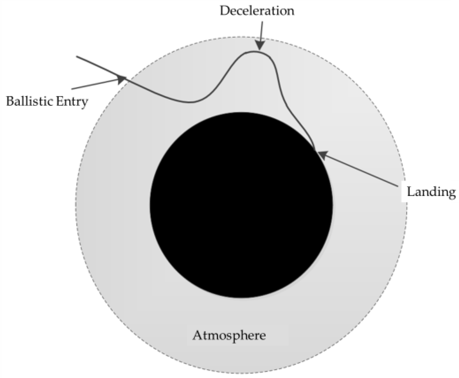
2.2. Typical Flight Environment
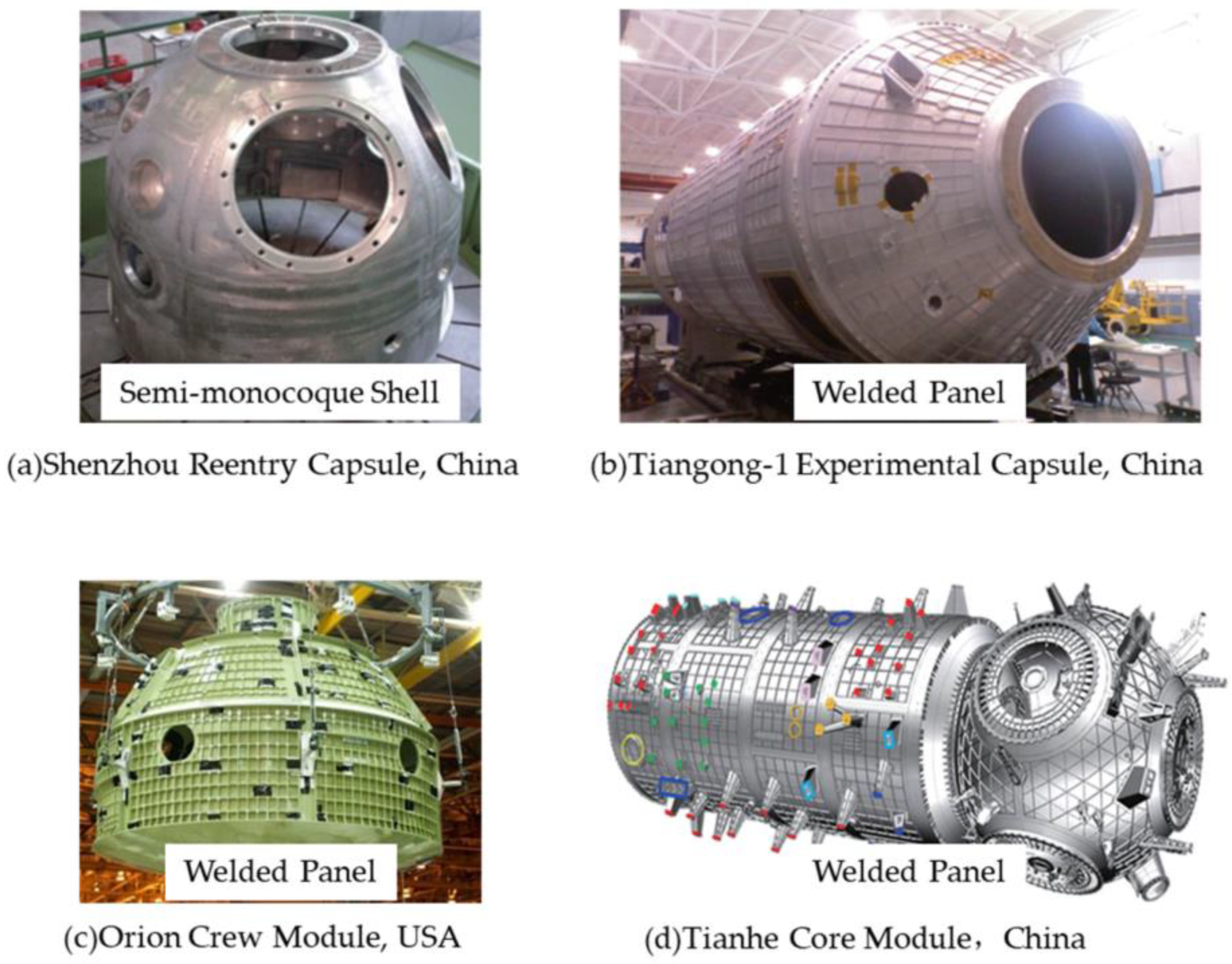
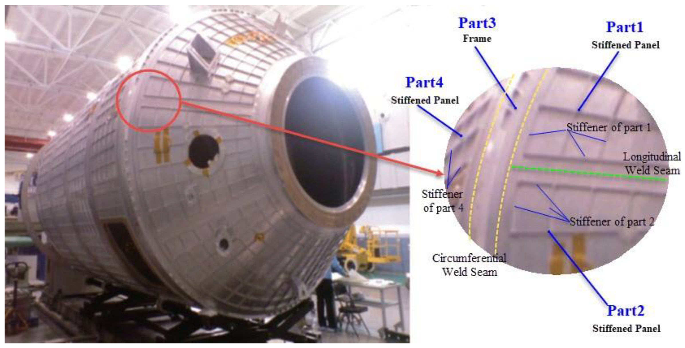
2.3. Pressurized Capsule Structure
2.4. The Development Course of Pressurized Capsule Structure
3. Structural Requirements of Manned Deep Space Exploration Pressurized Capsule
- (1)
- Lower structural weight [16]
- (2)
- Longer structural life requirements
- (3)
- Reusable function
- (4)
- More complex load conditions [7]
- (5)
- Higher spatial environmental adaptability
4. Technical Analysis of MDSEM
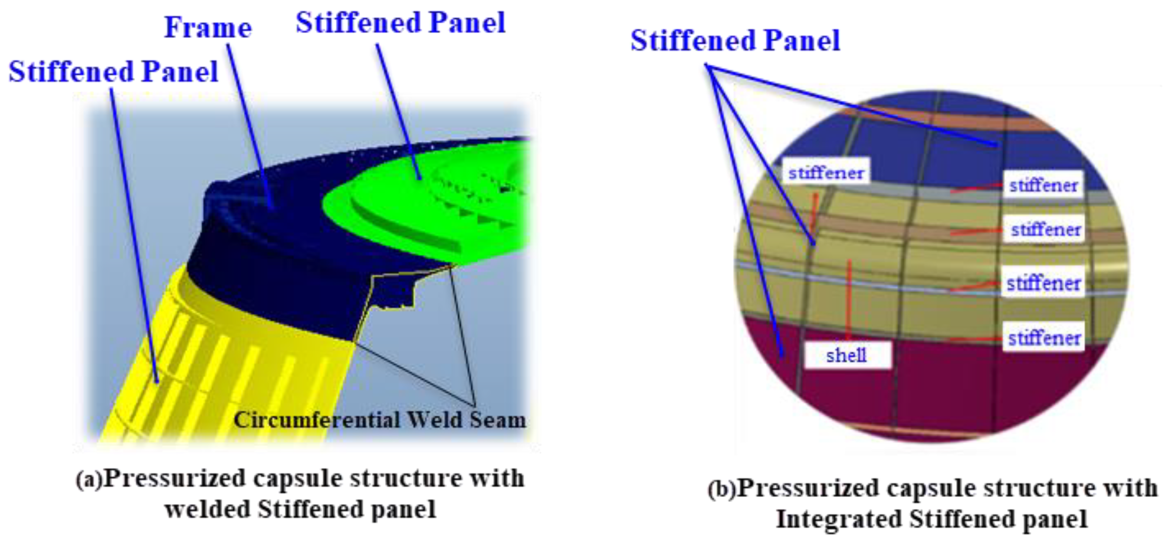
4.1. Problems Existing in WPPCS
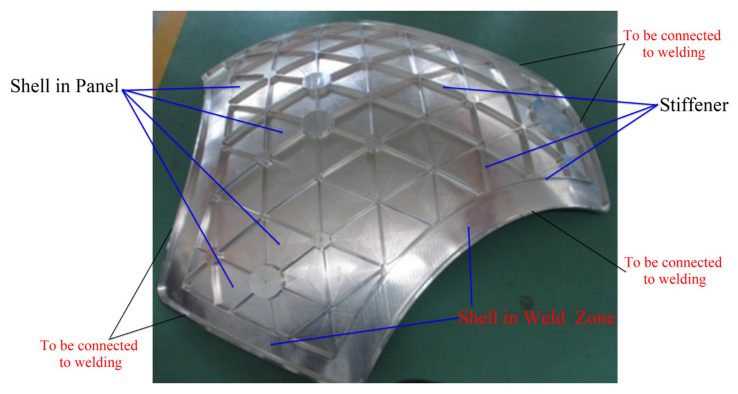
4.2. The Emergence of IPPCS
5. Research Progress on Key Technologies of IPPCS
- (1)
- The strength criterion of the pressurized capsule structure based on shakedown: the shakedown limit of the structure is taken as the ultimate bearing capacity of the internal pressure load of the pressurized capsule structure, which improves the bearing capacity of the structure (the post-yield performance of the material is applied) and the safety of the bearing capacity of the structure whose local material is in the plastic stage.
- (2)
- The design method of the IPPCS: a design process and optimization method for the IPPCS is proposed, which can guide the design of both local and overall structures.
- (3)
- Upgrading of pressurized capsule structure material: through the application research, the promotion of material upgrades for the pressurized capsule structure to materials such as 5B70 aluminum alloy.
- (4)
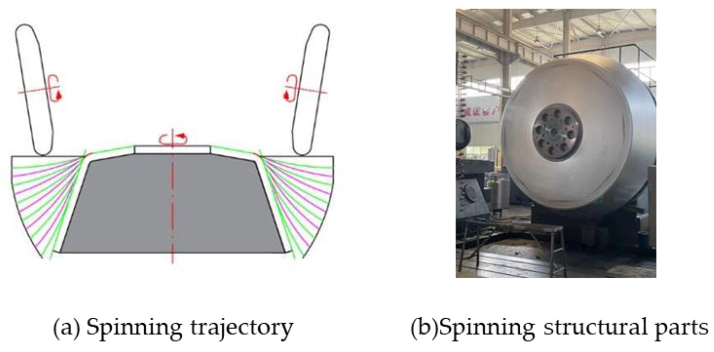
- The overall manufacturing process of pressurized capsule structure: master the spinning process of large-size parts and lay the foundation for the overall manufacturing of the pressurized capsule.
5.1. The Strength Criterion of the Pressurized Capsule Structure Based on Shakedown
5.1.1. Problems of Conventional Strength Criterion
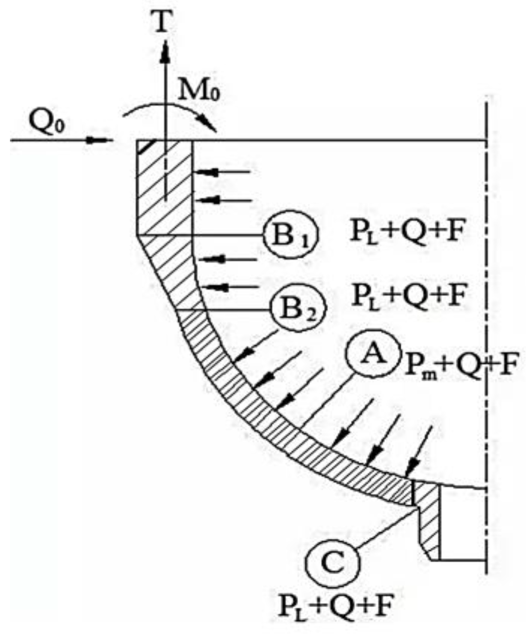
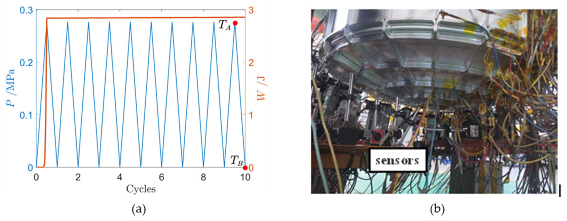
5.1.2. Application of Shakedown Theory on Pressurized Capsule Structure
- (1)
- (2)
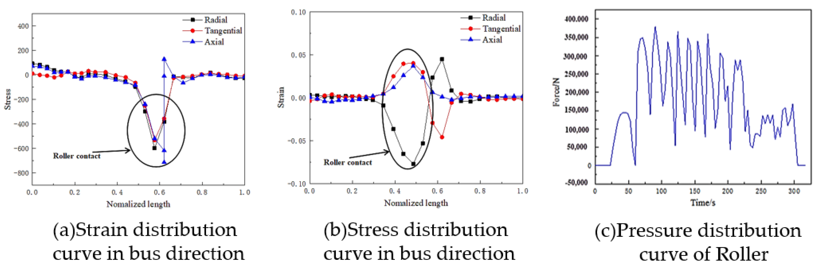
- Experimental verification of shakedown limit analysis of pressurized capsule structure
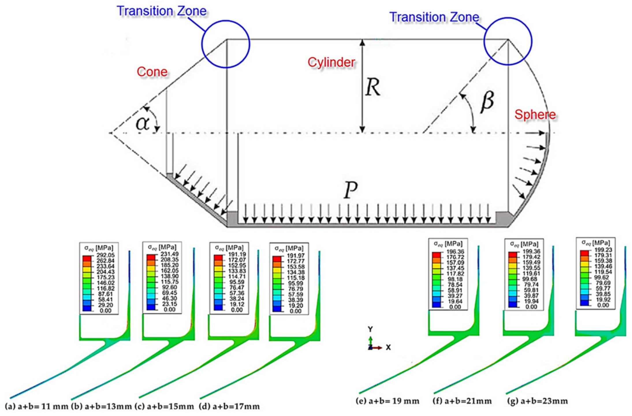
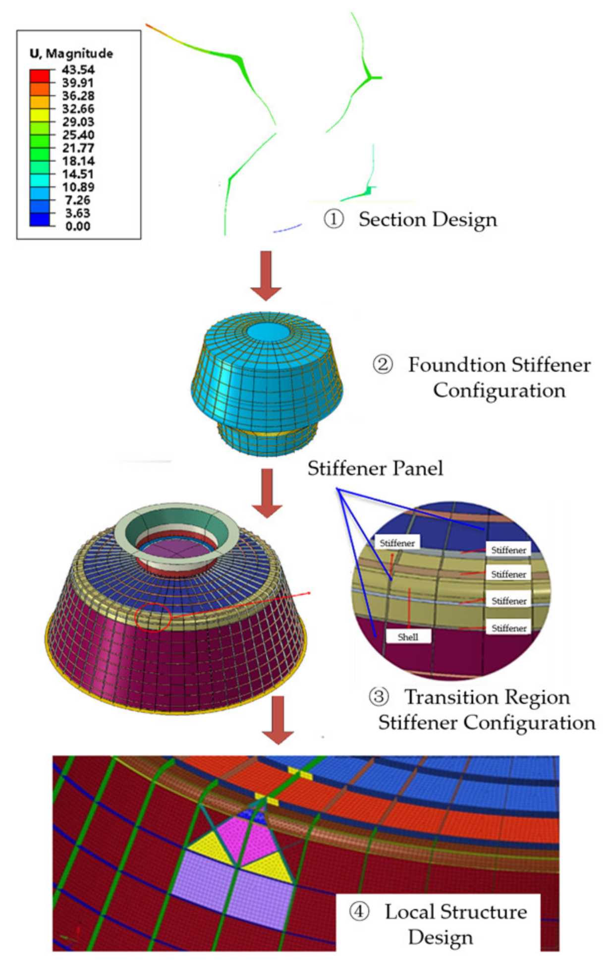
5.2. Research on the Design Method of IPPCS
- (1)
- (2)
- (3)
- Design of transition zone stiffener configuration [18]
- (4)
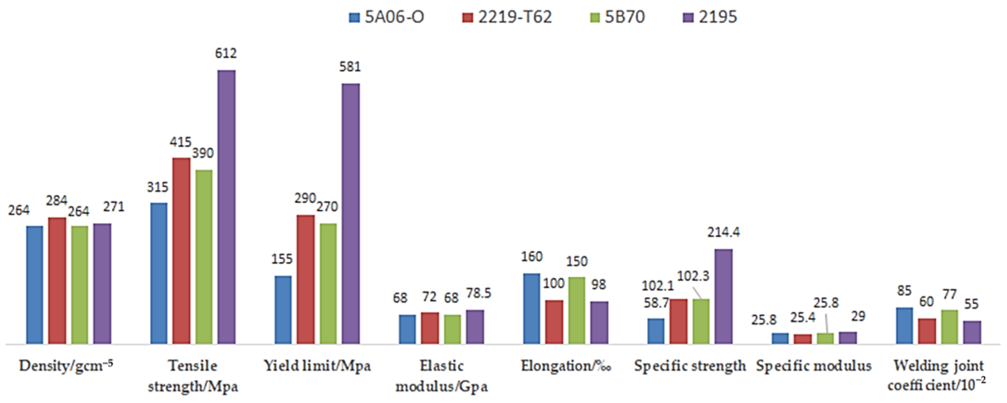
5.3. Material Upgrading of the Pressurized Capsule Structure
5.3.1. Application Analysis of Al-Mg-Sc Alloy in Pressurized Capsule Structure
5.3.2. Analysis of Application Potential of Al-Mg-Sc Alloy in Deep Space Exploration Pressurized Capsule Structure
- (1)
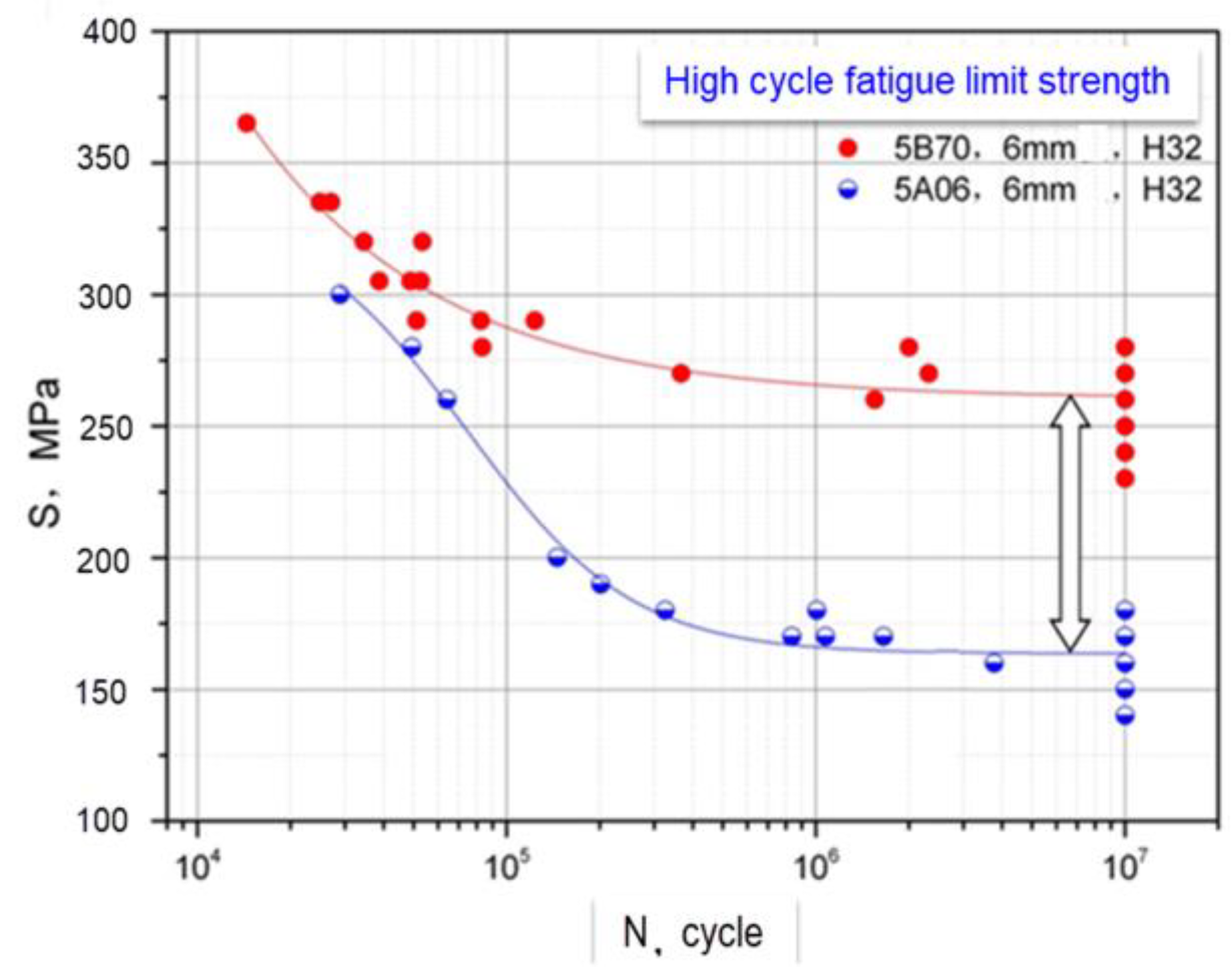
- Fatigue limit
- (2)
- Fracture toughness
- (3)
- Large size and ultra-large thickness plate supply
5.4. Research Progress on Manufacturing Technology of Pressurized Capsule Structure
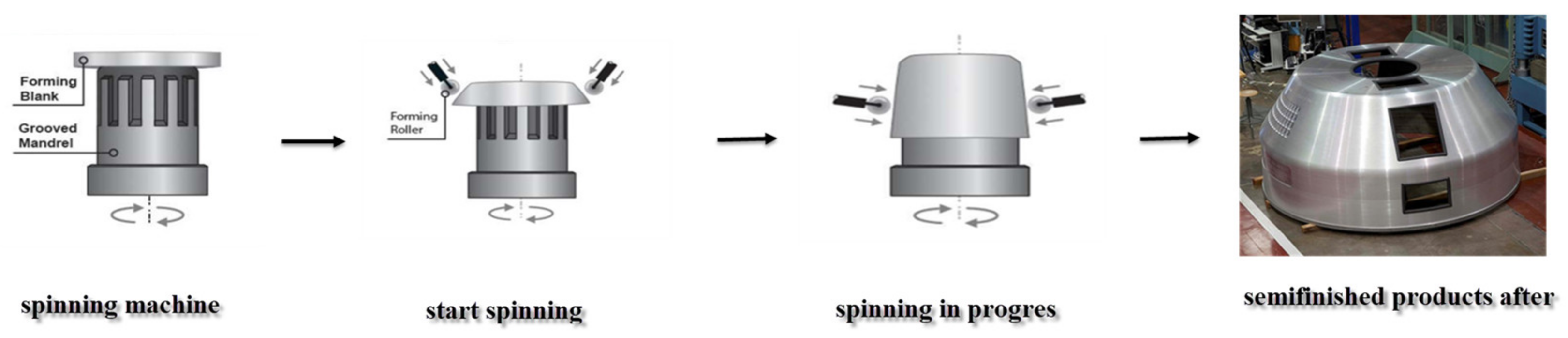
5.4.1. Analysis of the Spinning Process
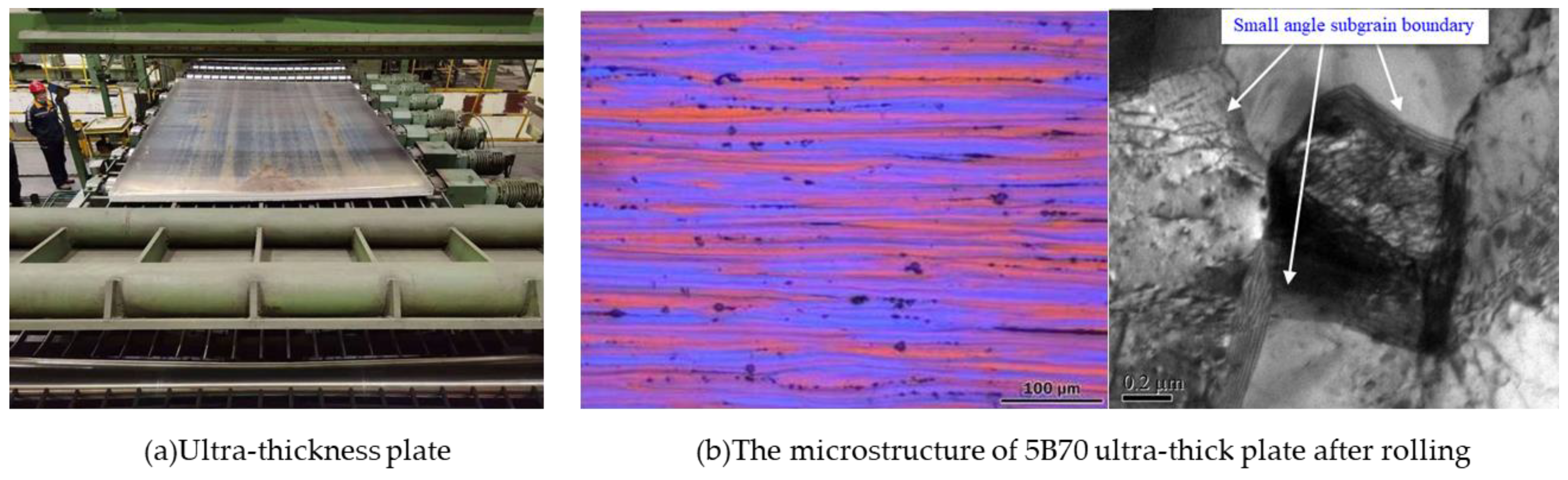
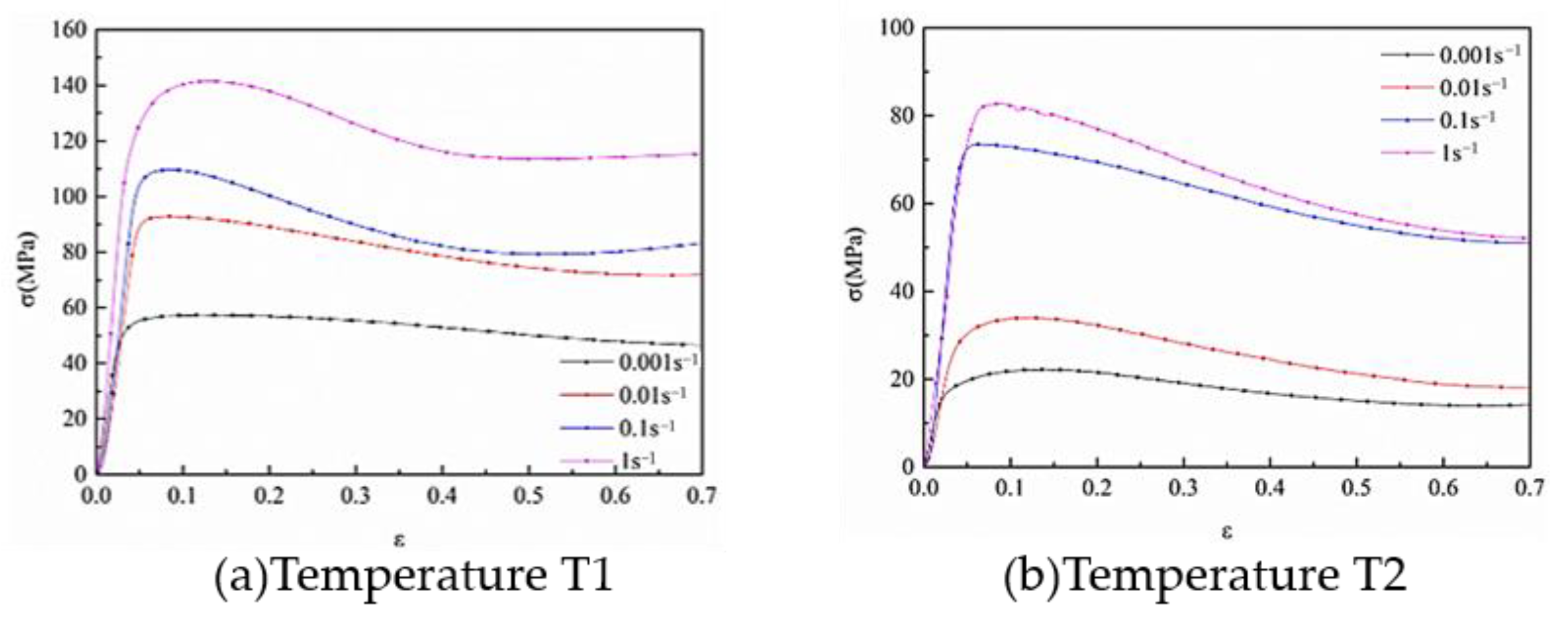
5.4.2. Research on Spinning Process of 5B70
6. Concluding Remarks
- (1)
- As an essential section of the manned spacecraft, the pressurized capsule structure is the key to realize the functions of bearing and sealing. With the stiffer requirements of the life and reliability of the pressurized capsule structure, the panel pressurized capsule structure represented by the WPPCS instead of the semi-monocoque shell type is the current mainstream pressurized capsule structure.
- (2)
- The MDSEM requires the pressurized capsule structure to have extremely low structural weight, long space service life of more than 15 years, reusability and adaptability to the harsh deep space environment. The conventional WPPCS has inherent shortcomings such as low bearing efficiency, large structural weight and conservative strength criterion, which makes it unable to be widely used in MDSEMs. As a method to meet the new requirements, the new structure of the IPPCS replaces the frame by the local panel structure, eliminates the segmentation of the weld zone, realizes the global stiffener continuity of the capsule, overcomes the shortcomings of the WPPCS and significantly improves the lightweight level of the pressurized capsule structure.
- (3)
- The key technology research progress of the IPPCS is rapid and has the engineering application conditions. The technical progress is organized as follows: Firstly, through the internal pressure cyclic loading experiment, the validity of the numerical analysis technology of the internal pressure shakedown limit of the pressurized capsule structure is verified. The bearing safety of the pressurized capsule structure with local plastic deformation can be evaluated by the shakedown analysis. A strength criterion of the pressurized capsule structure is added, that is, the allowable stress level of the local area of the pressurized capsule structure in the shakedown state should be higher than the yield strength of the material. Secondly, the IPPCS design method is proposed including four steps of shell cross-section, basic stiffener configuration, transition zone stiffener configuration and local structure, which guides the full realization of the optimization-based structural design in engineering applications and provides a tool guarantee for the structural design of the IPPCS. Thirdly, the 5B70 has excellent comprehensive performance, with the advantages of medium strength, weldability and corrosion resistance. It also meets the material selection requirements of the pressurized capsule structure, and can be widely used in the pressurized capsule structure instead of 5A06. Fourthly, the spinning process of large-size ultra-thick plates can realize the structural integrity manufacturing of the pressurized capsule structure, which provides a process guarantee for the development of the IPPCS.
- (1)
- The quantitative prediction method of internal pressure shakedown limit load of the pressurized capsule structure will be studied: The calculation time of numerical methods for the shakedown limit load is long, and sometimes it does not meet the need of rapid evaluation of bearing capacity. The establishment of approximate prediction formulas can quickly calculate the shakedown limit prediction load.
- (2)
- The structural technology of lightweight pressurized capsule structures with large temperature gaps will be studied: Extreme high and low temperature alternation is one of the challenges of MDSEMs. Providing suitable temperature conditions for the pressurized capsule structure through an independent thermal control subsystem is not conducive to reducing the weight of the spaceflight. The structural technology of the pressurized capsule adapted to the boundary of large temperature differences is the key to optimize the system scheme and cancel the thermal control subsystem.
- (3)
- The reuse design and verification technology of the IPPCS will be studied: Reuse can reduce the service cost of the high pressurized capsule structure. How to carry out the reuse design and verification of the pressurized capsule structure is the key technology that needs to be overcome in the future.
Author Contributions
Funding
Institutional Review Board Statement
Informed Consent Statement
Data Availability Statement
Conflicts of Interest
References
- Sairajan, K.K.; Nair, P.S. Design of low mass dimensionally stable composite base structure for a spacecraft. Compos. Part B Eng. 2011, 42, 280–288. [Google Scholar] [CrossRef]
- Belblidia, F.; Afonso, S.M.B.; Hinton, E.; Antonino, G.C.R. Integrated design optimization of stiffened plate structures. Eng. Comput. 1999, 16, 934–951. [Google Scholar] [CrossRef] [Green Version]
- Yu, D.Y.; Lai, S.B.; Chen, T.X. Technology progress of integral panel structure for large space station. Chin. Space Sci. Technol. 2011, 31, 31–40. [Google Scholar] [CrossRef]
- Zhao, C.X. Manufacturing Technology for large cabin structures of china manned spacecraft. Spacecr. Eng. 2022, 31, 234–240. [Google Scholar] [CrossRef]
- Ryazantsev, V.I.; Fedoseev, V.A. Welding the structure of the Buran orbital aircraft. Weld. Int. 1997, 11, 826–831. [Google Scholar] [CrossRef]
- Cheng, Z.L.; Wang, Z.K.; Zhang, Y.L. Analysis and optimization of lunar exploration architecture based on reusable human spacecraft. J. Spacecr. Rocket. 2019, 56, 910–918. [Google Scholar] [CrossRef]
- Baiocco, P. Overview of reusable space systems with a look to technology aspects. Acta Astronaut. 2021, 189, 10–25. [Google Scholar] [CrossRef]
- Cheng, Z.L. Research on Modeling and Optimization of Manned Exploration of the Moon System Using Reusable Trans-Lunar Injection Spacecraft; National University of Defense Technology: Changsha, China, 2017. [Google Scholar] [CrossRef]
- Adeel, M. Study on damage tolerance behavior of integrally stiffened panel and conventional stiffened panel. World Acad. Sci. Eng. Technol. 2008, 45, 1026–1030. [Google Scholar] [CrossRef]
- Wang, D.Z.; Xu, F.; Yuan, L.J.; Yuan, L.; Zhang, D.; Liu, J.; Hu, Y.; Kang, H.; Ma, Q.; Tong, Y.; et al. Brief introduction and recent development on the manufacture of aluminum alloy integral panels in aerospace applications. Int. J. Mater. Struct. Integr. 2021, 14, 299–318. [Google Scholar] [CrossRef]
- Swiech, L. Experimental and numerical studies of low-profile, triangular grid-stiffened plates subjected to shear load in the post-critical states of deformation. Materials 2019, 12, 3699. [Google Scholar] [CrossRef] [Green Version]
- Benfratello, S.; Giambanco, F.; Palizzolo, L. Optimal design of structures under dynamic loading. In Proceedings of the XIX Congresso Nazionale AIMETA, Ancona, Italy, 14–17 September 2009; pp. 14–17. [Google Scholar] [CrossRef]
- Giambanco, F.; Benfratello, S.; Palizzolo, L.; Tabbuso, P. Structural design of frames able to prevent element buckling. Proc. Elev. Int. Conf. Comput. Struct. Technol. 2012, 10, 4203. [Google Scholar] [CrossRef] [Green Version]
- Bernard, L.; Joel, W. Critical fracture of international space station modules following orbital debris penetration. In Proceedings of the Space Programs and Technologies Conference, Huntsville, AL, USA, 24–26 September 1996. [Google Scholar] [CrossRef]
- Pardini, C.; Anselmo, L. Monitoring the orbital decay of the Chinese space station Tiangong-1 from the loss of control until the re-entry into the Earth’s atmosphere. J. Space Saf. Eng. 2019, 6, 265–275. [Google Scholar] [CrossRef]
- Cole, T.J.; Bassler, J.; Cooper, S.; Stephens, V.; Ponnusamy, D.; Briere, M.; Betenbaugh, T. The challenges of designing a lightweight spacecraft structure for landing on the lunar surface. Acta Astronaut. 2012, 71, 83–91. [Google Scholar] [CrossRef]
- Caseiro, J.F.; Valente, R.A.F.; Andrade-Campos, A.; Yoon, J. On the elasto-plastic buckling of Integrally Stiffened Panels (ISP) joined by Friction Stir Welding (FSW): Numerical simulation and optimization algorithms. Int. J. Mech. Sci. 2013, 76, 49–59. [Google Scholar] [CrossRef]
- Li, H.Q.; Li, Z.C.; Cheng, Z.Z.; Zhou, Z.; Wang, G.; Wang, B.; Tian, K. A data-driven modelling and optimization framework for variable-thickness integrally stiffened shells. Aerosp. Sci. Technol. 2022, 129, 107839. [Google Scholar] [CrossRef]
- Lagaros, N.D.; Fragiadakis, M.; Papadrakakis, M. Optimum design of shell structures with stiffening beams. AIAA J. 2004, 42, 175–184. [Google Scholar] [CrossRef] [Green Version]
- Guo, J.; Li, W.; Wan, M.; Zhao, Y.; Li, C. Design of an innovative laser-assisted four-point bending forming process for high-stiffened structure of aluminum alloy. Opt. Laser Technol. 2021, 143, 107313. [Google Scholar] [CrossRef]
- Afonso, S.M.B.; Sienz, J.; Belblidia, F. Structural optimization strategies for simple and integrally stiffened plates and shells. Eng. Comput. 2005, 22, 429–452. [Google Scholar] [CrossRef] [Green Version]
- Slemp, W.C.H.; Bird, R.K.; Kapania, R.K.; Havens, D.; Norris, A.; Olliffe, R. Design, optimization, and evaluation of integrally stiffened Al-7050 panel with curved stiffeners. J. Aircr. 2011, 48, 1163–1175. [Google Scholar] [CrossRef] [Green Version]
- Simon, J.W. Direct evaluation of the limit states of engineering structures exhibiting limited, nonlinear kinematical hardening—ScienceDirect. Int. J. Plast. 2013, 42, 141–167. [Google Scholar] [CrossRef]
- Li, W.J.; Zeng, F.M.; Chen, G.; Deng, Y.; Liu, G.; Zhang, X.; Bezold, A.; Broeckmann, C. Shakedown analysis for structural design applied to a manned airtight module. Int. J. Press. Vessel. Pip. 2018, 162, 11–18. [Google Scholar] [CrossRef]
- Peng, H.; Liu, Y.H.; Chen, H.F.; Zhang, Z. Shakedown analysis of bounded kinematic hardening engineering structures under complex cyclic loads: Theoretical aspects and a direct approach. Eng. Struct. 2022, 256, 114034. [Google Scholar] [CrossRef]
- Spiliopoulos, K.V.; Panagiotou, K.D. A residual stress decomposition based method for the shakedown analysis of structures. Comput. Methods Appl. Mech. Eng. 2014, 276, 410–430. [Google Scholar] [CrossRef]
- Abdalla, H.F.; Megahed, M.M.; Younan, M.Y.A. A simplified technique for shakedown limit load determination. Nucl. Eng. Des. 2007, 237, 1231–1240. [Google Scholar] [CrossRef]
- Sun, Y.; Shen, S.L.; Xia, X.H.; Xu, Z.L. A numerical approach for predicting shakedown limit in ratcheting behavior of materials. Mater. Des. 2013, 47, 106–114. [Google Scholar] [CrossRef]
- Chinh, P.D. On shakedown theory for elastic–plastic materials and extensions. J. Mech. Phys. Solids 2008, 56, 1905–1915. [Google Scholar] [CrossRef]
- Liu, Y.H.; Carvelli, V.; Maier, G. Integrity assessment of defective pressurized pipelines by direct simplified methods. Int. J. Press. Vessel. Pip. 1997, 74, 49–57. [Google Scholar] [CrossRef]
- Carvelli, V.; Cen, Z.Z.; Liu, Y.; Maier, G. Shakedown analysis of defective pressure vessels by a kinematic approach. Arch. Appl. Mech. 1999, 69, 751–764. [Google Scholar] [CrossRef]
- Balakrishnan, S.; Veerappan, A.R.; Shanmugam, S. A comparative study of shape imperfection and internal pressure effects on plastic, shakedown and elastic limit loads using large and small strain formulation of 90° pipe bends. Int. J. Press. Vessel. Pip. 2021, 191, 104347. [Google Scholar] [CrossRef]
- Akoa, F.; Abdelkader, H.; An, L.T.H.; Said, M.; Tao, P.D. Application of lower bound direct method to engineering structures. J. Glob. Optim. 2007, 37, 609–630. [Google Scholar] [CrossRef]
- Yan, Z.; Wang, K.Y.; Li, H.X. Shakedown solutions for ballasted track structure under multiple uniform loads. Transp. Geotech. 2020, 51, 2343–2352. [Google Scholar] [CrossRef]
- Wang, J.; Yu, H.S. Shakedown analysis and its application in pavement and railway engineering. Comput. Geotech. 2021, 138, 104281. [Google Scholar] [CrossRef]
- Chen, G.; Wang, X.; Zhou, Z.; Zhang, L. Shakedown analysis of a reusable space capsule. Int. J. Mech. Sci. 2023, 244, 108028. [Google Scholar] [CrossRef]
- Chen, B.; Liu, G.; Kang, J. Design optimization of stiffened storage tank for spacecraft. Struct. Muhidiscip. Optim. 2008, 36, 83–92. [Google Scholar] [CrossRef]
- Tian, K.; Li, H.Q.; Huang, L.; Huang, H.; Zhao, H.; Wang, B. Data-driven modelling and optimization of stiffeners on undevelopable curved surfaces. Struct. Multidiscip. Optim. 2020, 62, 3249–3269. [Google Scholar] [CrossRef]
- Au, C.K.; Yuen, M.M.F. Unified approach to NURBS curve shape modification. Comput. Aided Des. 1995, 27, 85–93. [Google Scholar] [CrossRef]
- Li, Z.C.; Tian, K.; Zhang, S.; Wang, B. Efficient multi-objective CMA-ES algorithm assisted by knowledge-extraction-based variable-fidelity surrogate model. Chin. J. Aeronaut. 2022, 36, 213–232. [Google Scholar] [CrossRef]
- Zhang, W.J.; Zhang, F.; Zhang, G.H. Research on a algorithm of adaptive interpolation for NURBS curve. Appl. Mech. Mater. 2014, 687, 1600–1603. [Google Scholar] [CrossRef]
- Tian, K.; Lai, P.T.; Sun, Y.; Sun, W.; Cheng, Z.; Wang, B. Efficient buckling analysis and optimization method for rotationally periodic stiffened shells accelerated by Bloch wave method. Eng. Struct. 2023, 276, 115395. [Google Scholar] [CrossRef]
- Bajer, L.; Pitra, Z.; Repický, J.; Holeňa, M. Gaussian process surrogate models for the CMA evolution strategy. Evol. Comput. 2019, 27, 665–697. [Google Scholar] [CrossRef]
- Tian, K.; Gao, T.H.; Huang, L.; Xia, Q. Data-driven non-intrusive shape-topology optimization framework for curved shells. Aerosp. Sci. Technol. 2023, 139, 108405. [Google Scholar] [CrossRef]
- Shi, L.M.; Yang, P.; Zhou, Z.Y.; Cheng, Z.Z. Selection of main structural materials for spacecraft sealing cabins in China and abroad. Spacecr. Eng. 2013, 22, 136–141. [Google Scholar] [CrossRef]
- Wesley, T.; Marcia, D.; John, W.; Taminger, K.; Hoffman, E.; Newman, S. Development and Characterization of the Integrally Stiffened Cylinder (ISC) Process for Launch Vehicles and Aircraft Fuselage Structures. In Light Metals 2021; Springer International Publishing: Cham, Switzerland, 2021. [Google Scholar] [CrossRef]
- Wang, S.H.; Lai, X.M.; Wang, B.; Xu, W. Study on Integrated Manufacturing Technology of Non-welded Spacecraft Structure. Manned Spacefl. 2021, 27, 215–220. [Google Scholar] [CrossRef]


| Serial Number | Type | Spacecraft | Nation/Institution | Module Name | First Launch Date | Structure Form |
|---|---|---|---|---|---|---|
| 1 | manned spacecraft | Vostok | Russia | pressurized capsule | April 196 | s-MPCS |
| 2 | manned spacecraft | Mercury | USA | pressurized capsule | February 1962 | s-MPCS |
| 3 | manned spacecraft | Voskhod | Russia | pressurized capsule | October 1964 | s-MPCS |
| 4 | manned spacecraft | Gemini | USA | pressurized capsule | March 1965 | s-MPCS |
| 5 | manned spacecraft | Soyuz | Russia | reentry capsule orbital capsule | April 1967 | s-MPCS |
| 6 | manned spacecraft | Shenzhou | China | reentry capsule orbital capsule | November 1999 | s-MPCS |
| 7 | manned spacecraft | Apollo | USA | command capsule | July 1969 | s-MPCS |
| 8 | cargo spacecraft | Progress | Russia | cargo pressurized module | January 1978 | WPPCS |
| 9 | cargo spacecraft | Automatic transfer of aircraft | European Space Agency | cargo pressurized module | March 2008 | WPPCS |
| 10 | cargo spacecraft | Tianzhou | China | cargo pressurized module | April 2017 | WPPCS |
| 11 | space laboratory | Salyut | Russia | docking module orbital module | April 1971 | WPPCS |
| 12 | space laboratory | Skylab | USA | orbital module | May 1973 | WPPCS |
| 13 | space laboratory | Tiangong-1 space laboratory | China | experiment module | September 2011 | WPPCS |
| 14 | space station | Mir | Russia | core module | February 1986 | WPPCS |
| 15 | space station | Russia | Quantum-I/1 module | April 1987 | WPPCS | |
| 16 | space station | Russia | Crystal module | May 1990 | WPPCS | |
| 17 | space station | Russia | Spectrum module | May 1995 | WPPCS | |
| 18 | space station | Russia | Priroda module | April 1996 | WPPCS | |
| 19 | space station | International Space Station | Russia | Zarya cargo module | November 1998 | WPPCS |
| 20 | space station | USA | Unity node module | December 1998 | WPPCS | |
| 21 | space station | Russia | Zvezda service module | July 2000 | WPPCS | |
| 22 | space station | USA | Destiny experiment module | February 2001 | WPPCS | |
| 23 | space station | USA | Quest airlock module | July 2001 | WPPCS | |
| 24 | space station | Russia | Mooring compartment module | September 2001 | WPPCS | |
| 25 | space station | USA | Harmony node module | October 2007 | WPPCS | |
| 26 | space station | European Space Agency | Columbus experiment module | February 2008 | WPPCS | |
| 27 | space station | Japanese | Japanese experiment module | March 2008 | WPPCS | |
| 28 | space station | China Space Station | China | Tianhe core module | April 2021 | WPPCS |
| 29 | China | Wentian lab module | July 2022 | WPPCS | ||
| 30 | China | Mengtian lab module | October 2022 | WPPCS |
| Preset Crack Orientation | 5A06 KR(MPa·m1/2) | 5B70KR(MPa·m1/2) |
|---|---|---|
| Direction L | 105.6 | 115.018 |
| Direction T | 110.2 | 120.237 |
Disclaimer/Publisher’s Note: The statements, opinions and data contained in all publications are solely those of the individual author(s) and contributor(s) and not of MDPI and/or the editor(s). MDPI and/or the editor(s) disclaim responsibility for any injury to people or property resulting from any ideas, methods, instructions or products referred to in the content. |
© 2023 by the authors. Licensee MDPI, Basel, Switzerland. This article is an open access article distributed under the terms and conditions of the Creative Commons Attribution (CC BY) license (https://creativecommons.org/licenses/by/4.0/).
Share and Cite
Zhou, Z.; Yu, C.; Han, X.; Zheng, K.; Jiang, C.; Tian, K. Progress in Lightweight Design Methods for Large-Size Panel Structures in Manned Pressurized Capsules. Appl. Sci. 2023, 13, 8635. https://doi.org/10.3390/app13158635
Zhou Z, Yu C, Han X, Zheng K, Jiang C, Tian K. Progress in Lightweight Design Methods for Large-Size Panel Structures in Manned Pressurized Capsules. Applied Sciences. 2023; 13(15):8635. https://doi.org/10.3390/app13158635
Chicago/Turabian StyleZhou, Zhiyong, Chenfan Yu, Xiuzhu Han, Kaiwei Zheng, Chao Jiang, and Kuo Tian. 2023. "Progress in Lightweight Design Methods for Large-Size Panel Structures in Manned Pressurized Capsules" Applied Sciences 13, no. 15: 8635. https://doi.org/10.3390/app13158635