Article

Research on the Operational Performance of Organic Rankine Cycle System for Waste Heat Recovery from Large Ship Main Engine

Merchant Marine College, Shanghai Maritime University, Shanghai 201306, China
*
Author to whom correspondence should be addressed.
Appl. Sci. 2023, 13(14), 8543; https://doi.org/10.3390/app13148543
Submission received: 5 June 2023 / Revised: 6 July 2023 / Accepted: 11 July 2023 / Published: 24 July 2023
(This article belongs to the Special Issue Scientific Advances and Challenges in Ship Waste Heat Utilization)

Abstract

:
Based on the analysis of the waste heat distribution characteristics of a typical ship two-stroke low-speed main engine (model: MAN 8S65ME-C8.6HL, the specified maximum continuous rating SMCR: 21,840 kW) under different loads, two different types of organic Rankine cycle (ORC) systems, namely the basic system (BORC) and the preheated system(PORC), were constructed to recover the ship main engine’s exhaust gas waste heat and jacket cooling water waste heat. Using the thermodynamic simulation model of the system, the main performance indexes, including net output power of the two ORC systems were studied with the variation of seawater temperature and main engine load, and the annual ship fuel saving and annual carbon emission reduction generated by the two systems were compared and analyzed. It was found that the maximum net output power of the BORC system and PORC system were 445.3 kW and 491.3 kW, respectively, when the ship’s main engine load was 100%, and the outboard seawater temperature was 20 °C; the maximum thermal efficiency was 12.84% and 12.71%, respectively; under the annual operation, the fuel saving of BORC system and PORC system can be 456 tons and 510 tons, respectively, and the carbon emission reduction was 1416 tons and 1581 tons, respectively. The analysis found that the net output power of the PORC system is always greater than that of the BORC system. When the outboard seawater is lower, and the main engine load is more than 80%, the net output power difference between the PORC system and BORC system gradually expands, and the improvement of ORC system performance is more evident by adding a preheater. It can be concluded that when the ship was mainly operated in the sea area with low seawater temperature and the main engine was running under high load most of the time, selecting the PORC system to recover the waste heat of the main engine was more advantageous.

1. Introduction

At the 72nd session of the Marine Environment Protection Committee (MEPC) in April 2018, the International Maritime Organization (IMO) outlined a vision to decrease total greenhouse gas emissions from shipping by at least 50% by 2050, compared to the levels recorded in 2008 [1]. The marine diesel engine remains a prevalent choice as the main engine for ships, yet only around half of the energy produced through fuel combustion in the ship’s main engine is effectively converted into useful work. The remaining portion is released into the surrounding environment as waste heat, resulting in substantial energy wastage and concurrent marine atmospheric pollution [2]. Hence, enhancing the utilization of waste heat generated by the ship’s main engine is a primary approach towards attaining the IMO’s objectives of reducing greenhouse gas emissions and achieving energy efficiency and carbon reduction in ships. Among the various waste heat recovery technologies available, the organic Rankine cycle (ORC) technology offers distinct advantages in recycling low-grade waste heat, ensuring safety, and adaptability. Consequently, it is well-suited for recovering waste heat generated by a ship’s main engine [3].
The waste heat produced by the ship’s main engine dissipates primarily through various channels, including exhaust smoke, pressurized air, cooling water for cylinder liners, and lubricating oil. Among these, the largest share of waste heat is attributed to exhaust gas [4]. Currently, extensive research is being conducted on the retrieval of waste heat from the main engines of ships.
Shu et al. [5] employed a base-type organic Rankine cycle (ORC) system to capture and utilize the waste heat emanating from the turbocharger and exhaust gas boiler, which carries high-temperature exhaust flue gas from a cruise ship. By implementing a reheat ORC system, Girgin et al. [6] successfully harnessed the waste heat from a warship’s power-generating diesel engine, rated at 1000 kW, resulting in a remarkable net output of 118 kW. Diao et al. [7] investigated the key factors that influence the performance of the ORC system in recovering waste heat from diesel exhaust gas. The exergy analysis revealed the need for enhancing the utilization rate of waste heat, which can be achieved by augmenting the preheater or regenerator components. Yang et al. [8] developed a comprehensive approach by establishing a thermodynamic model, an economic model, and a system optimization model for the ORC system used in recovering waste heat from ship diesel engine exhaust gas. They conducted a comparative analysis of the system’s performance using six distinct working fluids, thereby examining the effects and efficiency of each fluid.
Aside from the waste heat generated by exhaust gas, other forms of waste heat from the main engine also possess significant potential for recovery. Numerous research studies have put forward the implementation of diverse ORC systems to capture and utilize various types of waste heat produced by ship main engines. Han et al. [9] presented a novel concept for an ORC system consisting of three loops. This innovative design involves the integration of two loops that overlap, utilizing the high-temperature flue gas from the host as the primary heat source. Additionally, a separate subsystem is formed, utilizing the host cylinder liner cooling water as another heat source. The condensers in these two subsystems operate in series and employ flash natural gas as the cooling medium. In their research, Liu et al. [10] introduced an innovative approach that combines the steam Rankine cycle and the organic Rankine cycle to enable simultaneous recovery of waste heat from the ship’s main engine and the cylinder liner cooling water. Furthermore, they utilized the cylinder liner cooling water to preheat the mass in the exhaust heat recovery circuit. This integration resulted in a remarkable improvement of 4.42% in overall efficiency. In their study, Ma et al. [11] implemented a strategy in the ORC system where the working fluid is preheated using waste heat from the main engine’s jacket cooling water. Following the preheating process, the working fluid is directed to the evaporator to facilitate direct heat exchange with the high-temperature exhaust gas. This approach enables the effective cascade utilization of waste heat energy. Akman and Ergin [12] analyzed the possibility of using an ORC system to simultaneously recovers three forms of waste heat from a Two-stroke diesel engine exhaust, charge air and cylinder liner cooling water, and calculated and analyzed that the system could reduce the ship’s carbon emissions by 6.9%. Song et al. [13] built two separate ORC systems to recover two forms of wasted energy from a maritime vessel’s medium-speed diesel engine. They succeeded in increasing the diesel engine’s thermal efficiency by 10.2%, and the net output power of the two systems reached 101.1 kW. Soffiato et al. [14] improved the central cooling system of an LNG vessel with electric propulsion and built various types of ORC systems with a maximum net output of 820 kW for recovering waste heat from charge air cooling, cylinder liner cooling water, and lube oil cooling. Grljusic et al. [15] used an ORC system driven by exhaust gas, cylinder liner cooling water, and booster air waste heat from the main engine of an oil tanker for power generation. Sung and Kim [16] used exhaust gas and cylinder liner cooling water as the ORC system heat source to recover waste heat from a dual-fuel main engine of an LNG vessel at the same time, and the net output power of the ORC system could reach 5.17% of the power of the main engine. Luo et al. [17] built three types of ORC systems to collect waste heat from a ship’s medium-speed diesel engine’s exhaust gas and jacket cooling water.
There are few studies to investigate BORC and RORC systems in terms of actual operating parameters of specific types of marine main engines, and no specific calculations have been made to analyze the fuel savings and carbon emissions during the whole year. In this work, the MAN 8S65ME-C8.6HL model with complete operating parameters under standard operating conditions (sweep gas temperature 25 °C, ambient temperature 25 °C) is selected based on the operating parameters of each model provided in the CEAS database for the low-speed two-stroke diesel fuel that is currently in common use, and the type and distribution of waste heat generated by this type of diesel engine under various operating loads is first investigated. Two ORC models are constructed with reference to the actual operating parameters of the main engine of a type of ship, using exhaust gas and cylinder liner cooling water waste heat, analyzing the effects of seawater temperature and load changes on system performance during the voyage of the main engine. Finally, supplementing with the comparison data between PORC and BORC, the advantages of the PORC system are explored, examining the fuel savings and carbon emission reduction of the ship throughout the year; and the initial cost of ORC system and payback period are estimated and analyzed.

2. Materials and Methods

2.1. Main Engine Parameters

The ship’s main engine model is MAN 8S65ME-C8.6HL; Maximum sustainable Rating (SMCR): 21,840 kW, speed: 95 r/min, number of cylinders: 8, diameter: 650 mm. According to the Computerized Engine Application System (CEAS) [18], database of MAN Corp, the performance parameters of this type of main engine are shown in Table 1 under standard operating conditions (sweep temperature 25 °C and ambient temperature 25 °C). The low calorific value of the main engine fuel is 42,700 kJ/kg, and the thermal efficiency of the waste gas boiler is 90%.

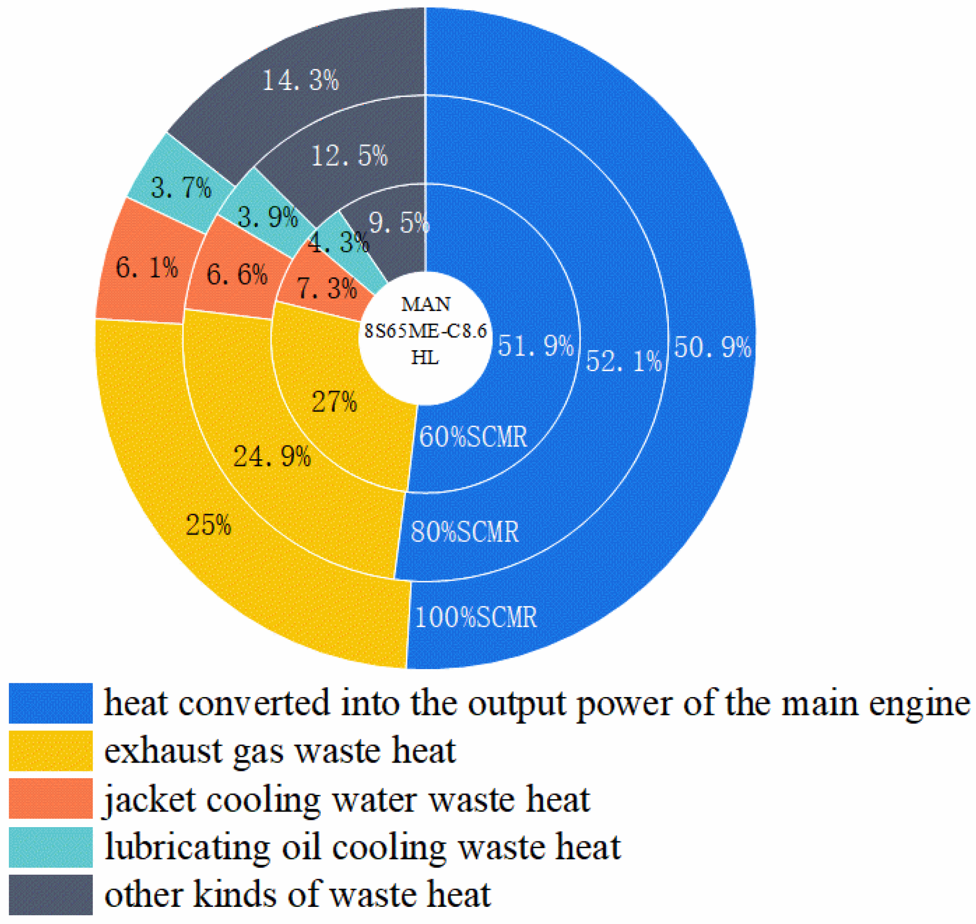
2.2. Distribution of Main Engine Waste Heat

The unused energy produced by a ship’s main engine mainly includes heat in the flue gas, heat in the cooling water of the cylinder liner, heat in the lubricating oil and other forms of waste heat. The heat balance equation of the main engine is shown in Equation (1).
Q f = Q e + Q s + Q w + Q o + Q r
where: Q f is the entire amount of heat produced by fuel combustion; Q e is the that is converted into the actual output work of the host; Q s is the heat taken away by the smoke exhaust from the host; Q w is the heat taken away by the cooling water of the host cylinder liner; Q o is lubricating oil cooling waste heat; are other kinds of waste heat, including pressurized air cooling waste heat, radiation heat dissipation, etc.
The unused energy produced by a ship’s main engine is Q f , as shown in Equation (2).
Q f = M f × H u
where: M f is the consumption of host fuel, kg/h; H u is the fuel’s low calorific value, kJ/kg.
M f can be calculated by the following Formula (3).
M f = S M C R × S F O C M E 10 3
where: S F O C M E is the fuel consumption rate of the ship’s main engine, g/kWh.
The exhaust heat of the ship’s main engine is Q s , as shown in Equation (4).
Q s = m s × C p , s × ( T s T i s o )
where: m s is the mass flow rate of host flue gas, kg/s; C p , s is The specific heat capacity under constant pressure, kJ/(kg∙k); T s is the flue gas temperature emitted from the host, °C; is the operating temperature of the main engine, °C.
Qw and Qo are the heat taken away by cylin T i s o der liner cooling water and lubricating oil cooling respectively, which can be obtained by querying the CEAS database; Qe is the heat converted into the output work of the main engine, which is the effective output power of the main engine of the ship, and the effective output power of the main engine under different loads can be obtained by querying the CEAS database; Qs can be calculated by the above formula; thus, the quantity of various forms of heat of the main engine under different loads can be calculated and obtained, as shown in Table 2. The amount of various forms of heat produced by the main engine grows as the load on the main engine increases. The main engine’s exhaust heat contributes to roughly half of the total waste heat. The temperature of the main engine’s exhaust heat is high grade and easy to recycle. Typically, the ship owner has an exhaust gas boiler installed to recover and reuse the waste heat from the exhaust gas to make high-temperature steam (150–180 °C) for ship usage. However, the amount of water steam required for the ship to function is restricted. When the main engine is under heavy load, a considerable amount of exhaust gas is bypassed, therefore really realized recovery accounts for less than 20% of total exhaust gas heat loss. Many exhaust gas residual heat still can not be effectively recovered. The working temperature of cylinder liner cooling water is 70 °C to 95 °C, the temperature grade is relatively high, the flow rate is sufficient and stable, and the waste heat recovery potential of cylinder liner cooling water is significant. The working temperature of the main engine lubricating oil is about 50 °C, the temperature grade is low, and the waste heat proportion is small, so it isn’t easy to recover effectively. Other types of waste heat include pressurized air cooling waste heat, radiation heat, etc.; it is difficult to recover due to the significant temperature grade change and other reasons.
The thermal balance analysis of the main engine under different loads is shown in Figure 1. Under different loads, the adequate output power of the main engine maintains about 51% of the entire amount of heat produced by fuel consumption, and the other 49% of the energy is lost to the atmosphere as waste heat. With increasing the main engine load, the proportion of exhaust gas waste heat, jacket cooling water waste heat, and lubricating oil cooling waste heat decrease. When the burden of the main engine increases from 60% to 100%, the exhaust gas waste heat decreases from 27% to 25%, the cylinder liner cooling water waste heat decreases from 7.3% to 6.1%, and the lubricating oil cooling waste heat decreases from 4.3% to 3.7%. The proportion of other types of waste heat increases with the ship’s main engine load increase, from 9.5% to 14.3%. This is mainly because the pressurized air cooling waste heat in this type of waste heat increases significantly with the rise of the main engine load. The above analysis shows that the exhaust gas waste heat accounts for a large proportion, and the temperature grade is high. Although the jacket cooling water accounts for a small proportion, the temperature grade is high, and the quantity is stable. Under different engine loads, these two kinds of waste heat of ship engines have great potential and utilization value and can be effectively recovered by the ORC system.

3. ORC System Structure and Design Parameters

The arrangement of the evaporator in the flue of the main engine within the ORC system, when used for recovering waste heat from the engine’s exhaust gas, poses several drawbacks. Directly heating the working fluid in the evaporator with high-temperature flue gas not only raises the exhaust gas back pressure of the main engine and hampers its efficiency but also facilitates the occurrence of carbon corrosion in the evaporator. Henceforth, in this research paper, the waste heat from the main engine’s exhaust gas is recuperated in an indirect manner. To begin, the waste heat from the main engine’s exhaust gas is used to power the waste gas boiler, which produces a vast amount of high-temperature water steam. The high-temperature water steam is then used as the ORC system’s heat source to heat the working fluid in the evaporator, reducing the detrimental influence of the ORC system evaporator on the main engine’s performance. Furthermore, it can ensure the stability of the ORC system’s heat source quality, which is beneficial to actual ship application and ORC system operation dependability.
Among several possible organic working fluids, R365mfc offers the advantages of excellent safety, good chemical security, lower ODP and GWP values, and other properties that make it appropriate for waste heat recovery below 200 °C [19]. As a result, R365mfc is chosen as the ORC system’s circulating working fluid in this investigation. Figure 2a,b illustrate the structure composition of the built basic ORC (BORC) system and warmed (PORC) system. BORC is driven by high-temperature water vapor generated from the ship’s exhaust gas boiler, and uses seawater as the cooling water for the system. The liquid mass (R365mfc) is pressurized and fed into the evaporator by the mass pump, the heat emitted by the high-temperature water vapor is absorbed in the evaporator and turned into a high-temperature, high-pressure gaseous mass, which is expanded into the expander to do work and drive the generator, resulting in the generation of electricity. The gaseous mass from the expander outlet enters the condenser and is cooled and condensed into a liquid mass by the outboard seawater and then enters the storage tank, which is then pressurized by the mass pump and enters the next cycle of power generation. The PORC system differs from the BORC system in that it includes a preheater in front of the evaporator and uses the cylinder liner cooling water to preheat the working mass before it enters the evaporator.
Table 1 shows that when the main engine load is raised from 60% to 100%, the exhaust gas temperature of the main engine decreases and then rises and is lowest at 75% load, with a temperature of 214 °C, and highest at 100% load, with a flue gas temperature of 234 °C; the temperature of the main engine’s exhaust gas decreases and then rises and is lowest at 75% load, with a temperature of 214 °C, and highest at 100% load, with a flue gas temperature of 234 °C; When the main engine’s load grows from 60% to 100%, the exhaust gas temperature of the main engine initially lowers and then climbs. The lowest temperature is 214 °C at 75% load, and the highest temperature is 234 °C at 100% load. Additionally, the mass flow rate of flue gas increased from 33.8 kg/s to 49.3 kg/s, the flow rate of water steam produced by the exhaust gas boiler increased from 2050 kg/h to 3530 kg/h, and the temperature of high-temperature water steam was 180 °C. Under different main engine loads, the heat source temperature (i.e., high-temperature water steam temperature) at the evaporator of the ORC system can be kept constant, and its mass flow rate increases as the main engine load increases. The inlet and outlet temperatures of the jacket cooling water are 85 °C and 71 °C, respectively. In the PORC system, the working fluid at the preheater outlet is preheated to 80 °C. The design parameters of the constructed ORC system are shown in Table 3. To facilitate the investigation and comparative analysis of the consequences of the system performance on the main engine load and the outboard sea temperature in the ORC system constructed in this paper, the results of the system operating conditions on the performance of the working fluid pumps and expander are ignored, and the isentropic efficiency is fixed. Relevant impact analysis will be taken into account in the subsequent research work.

4. Evaluation Index of ORC System

Simulink software 8.5 was used to do a thermodynamic simulation of the ORC system. The modeling process and verification of the system model can be found in the reference [17]. Thermal efficiency and the net output power are employed as the key evaluation indices of the ORC system’s thermodynamic operation performance in this research, and the ship’s fuel savings and carbon emission reduction are used to evaluate the system’s energy saving and environmental protection.
As stated in Equation (5), the net output power of the ORC system is defined as the difference between the output power of the expander and the power consumption of the working fluid pump.
W n e t = W exp W p u m p
Equation (6) exhibits the definition of the thermal efficiency for the BORC system, which quantifies the proportion of the system’s net output power to the heat assimilated by the working fluid within the evaporator.
η B O R C = W n e t Q v a p o r = W exp W p u m p Q v a p o r
For the PORC system, the total heat consumption includes the heat absorbed in the preheater Q J W , as shown in Equation (7), because the system increases the waste heat of cylinder liner cooling water as the heat source of the preheater.
η P O R C = W n e t Q v a p o r + Q J w = W exp W p u m p Q v a p o r + Q J w
The fuel savings M o i l can be calculated from the net output work used by the ORC system for power generation, as shown in Equation (8).
M o i l = W n e t × S F O C A E × t 10 6
where: S F O C A E is the fuel consumption rate of a diesel engine, 215 g/kWh [20]; t is the time of system operation in h.
The fuel saving rate is expressed as the percentage of fuel savings to total fuel consumption of the main engine, as shown in Equation (9).
F = M o i l M f × 100 %
Carbon emissions are able to be minimized by reusing waste heat from the ship’s main engine, as illustrated in Equation (10).
M C O 2 = M o i l × C F
where is the CO2 emission factor of fuel oil, and the heavy fuel oil is 3.1t-CO2/t-fuel [21].

5. Discussion

5.1. Influence of Seawater Temperature on System Performance

The temperature of the water changes as the ship travels in different seas and seasons. The BORC and PORC systems use the outboard sea water as the heat sink, and the seawater temperature change will influence the system’s performance. Figure 3a illustrates the impact of seawater temperature on the condensation temperature and expansion ratio of the ORC system, assuming constant heat source temperature and flow rate. As the seawater temperature rises, the condensation temperature of the ORC system experiences an increase, while the expansion ratio undergoes a decrease. When the seawater temperature is increased from 293.15 K to 303.15 K, the condensation temperature increases from 332.9 K to 342.8 K in the BORC system, and the expansion ratio decreases from 10.5 to 8.0. In the PORC system, the condensing temperature increases from 334 K to 343.3 K, and the expansion ratio drops from 10.9 to 8.1. The impact of variations in seawater temperature on both the condensation temperature and expansion ratio remains consistent across the BORC and PORC systems.
The influence of seawater temperature on the net output power and thermal efficiency of the ORC system is shown in Figure 3b. With the increase in seawater temperature, the net output power of the BORC and PORC systems decreases. As the seawater temperature rises, the net output power of both the BORC and PORC systems experiences a decline. When the seawater temperature rises from 293.15 K to 303.15 K, the net output power of the BORC system undergoes a reduction from 445.3 kW to 405.5 kW, representing a decrease of 8.94%. The net output power of the PORC system is reduced from 491.3 kW to 426 kW by 13.29%. The net output power of the PORC system is always greater than that of the BORC system. The addition of the preheater yields a notable enhancement in the net output power of the ORC system, resulting in an improvement ranging from 5% to 10.3%. The significance of this increase becomes more pronounced under lower seawater temperatures. Hence, in scenarios where the ship predominantly operates in sea areas characterized by lower temperatures, it is advisable to prioritize the PORC system for efficient recovery of unused heat from the main engine. In relation to the thermal efficiency of the system, it is observed that as the seawater temperature rises, the net output power of the system decreases. Consequently, a corresponding decrease in the system’s thermal efficiency occurs. The thermal efficiency of the BORC system depth drops from 12.84% to 11.70% as the seawater temperature rises from 293.15 K to 303.15 K. The thermal efficiency of the PORC system fell from 12.71% to 11.54%. As a result, the thermal efficiency of the PORC system is slightly lower than that of the BORC system.

5.2. Influence of Main Engine Load on System Performance

As shown in Table 2, the variation in waste heat recoverable by the ORC system is contingent upon the different loads at which the main engine operates. The influence of the main engine load on the working fluid flow and net output power of the ORC system is shown in Figure 4a. The working fluid flow of the ORC system increases with the main engine load. As the main engine load escalates from 60% to 100%, the BORC system experiences a rise in the working liquid flow speed from 7.30 kg/s to 13.30 kg/s, while the PORC system witnesses an increase in the working liquid flow speed from 8.45 kg/s to 14.91 kg/s. The increase in the main engine load leads to a corresponding rise in the waste heat recoverable by the ORC system. Consequently, the mass flow rate of the working fluid within the ORC system also increases in accordance with the heat absorption capacity. As seen in Figure 4a, the net output power of the ORC system tem rises with the increase of the main engine load. When the main engine load increases from 60% to 100%, the net output power of the BORC system increases from 237.4 kW to 445.3 kW, increasing by 87.57%. The net output power of the PORC system demonstrates a remarkable increase, rising from 270.0 kW to 491.3 kW, signifying an 81.96% improvement. Moreover, the net output power of the PORC system consistently surpasses that of the BORC system. Notably, as the main engine load escalates to 80%, the rate of net output power increment for the PORC system progressively accelerates.
The influence of the main engine load on the thermal efficiency and expansion ratio of the ORC system is shown in Figure 4b. As the main engine load increases, the two systems’ thermal efficiency and expansion ratio decrease first and then increase, and the change rule is the same. The thermal efficiency of BORC and PORC systems reach the maximum value under 100% load, which is 12.84% and 12.71%, respectively. As illustrated in Figure 4b, When the main engine’s load becomes 80%, the exhaust system expansion ratio is the lowest. The system expansion ratio defines the work capacity of the unit working fluid, which influences the system’s net output power. In accordance with the comprehensive analysis of Figure 4a,b, when the main engine load raises from 60% to 80%, the mass flow rate of the fluid being used increases gradually, but the system expansion ratio decreases and the work capacity of the unit working fluid decreases. The net output power of the system exhibits a direct correlation with both the mass flow of the working fluid and the work capacity of the working fluid per unit mass. As a result, within the range of this load, the net output power of the system experiences a gradual and moderate increase. When the burden of the main engine rises from 80% to 100%, not only does the expansion ratio of the system increase, but also the flow rate of the ORC system working mass increases. Consequently, the net output power of the system experiences a significant surge, followed by a subsequent decline in the system’s thermal efficiency. The thermal efficiency of the system is directly influenced by the net output power, while inversely affected by the heat absorption capacity. Initially, the thermal efficiency decreases, but subsequently exhibits an increase as the main engine load escalates.
The effect of load changes on the difference and increase in net output power of the two systems is shown in Figure 5. When the main engine load is between 60% and 80%, the average increase in net output power of the BORC due to the addition of a preheater can reach 32.3 kW. When the host load reaches 80%, the difference in net output power between the PORC system and the BORC system steadily widens; as the load on the main engine goes from 80% to 100%, the net output power difference between the two systems grows from 34.1 kW to 46 kW. This indicates that with the increase of the main engine load, the improvement of BORC system performance will be more evident by increasing the preheater. Therefore, when the ship mainly operates under high load conditions (80%SMCR or above), the advantage of using the PORC system to reclaim the waste heat from the main engine will be more visible. The increment in the net output power of the preheater incorporated in the BORC system shows a diminishing trend as the main engine load rises. Specifically, as the main engine load increases from 60% to 100%, the rate of net output power increase decreases from 13.73% to 10.33%. This phenomenon occurs due to the accelerated increase in net output power of the BORC system as the main engine load escalates, leading to a reduction in the magnitude of the increment.

5.3. Analysis of Carbon Emission Reduction and Payback Period

As shown in Table 1, when the main engine runs at 85%SMCR, fuel consumption per hour is 3016.7 kg/h. The diesel engine’s fuel consumption rate stands at 215 g/kWh, and the BORC system and PORC system can obtain a net output power of 293.1 kW and 329.2 kW, respectively. Therefore, carbon emission reduction can be estimated approximately from the fuel consumed. Assuming that the ship’s main engine is running at 85% SMCR for 300 days with heavy oil, the BORC system can save 1.52 tons of fuel oil per 24 h on average by utilizing unused energy from the ship’s main engine, with a fuel-saving rate of 2.10%, saving 456 tons of fuel oil and 1416 tons of carbon emissions reduction in a year. Using the PORC system to recover the waste heat of the ship’s main engine can save 1.70 tons of fuel every day on average, with a fuel-saving rate of 2.40%. The annual fuel saving and carbon emission reductions are estimated at 510 tons and 1581 tons, respectively. When compared to the BORC system, the PORC system can save 11.7% more oil and reduce carbon emissions by 11.7%, which has clear advantages. It is worth emphasizing that actual carbon emission reduction should take into account variations in ship types, fuel class selection, actual sailing conditions of ships, environmental changes, and others.
The investment initial cost of the ORC system in 2022 is calculated by the following equation [5,22]:
C 2022 = C 2001 C E P C I 2022 C E P C I 2001
Among them, CEPCI2022 published by the American Institute of Chemical Engineers is 688.8, and CEPCI2001 is 397 [23].
The total investment cost in 2001 can be expressed as:
C 2001 = C V + C c o n + C exp + C f , p
CV, Ccon, Cexp and Cf,p denote the investment cost of evaporator, condenser, expander and mass pump respectively, calculated as follows:
C exp = 3.5 × [ 10 e ( 2.705 + 1.44 × lg W exp 0.177 lg ( W exp ) 2 ) ]
C con = 1397 A c o n 0.89
C V = 1397 A V 0.89
C f , p = 1120 W f , p 0.8
Wexp denotes expander output power, kW; Wf,p denotes work pump power consumption, kW; Acon and Av denote condenser and evaporator heat transfer area, respectively.
Assuming an average seawater temperature of 25 °C, recovering of waste heat generated by 85% SMCR, the cost of the BORC system is approximately 640 thousand dollars and the cost of the PORC system is approximately 1.12 million dollars. Based on the fuel oil price provided by SHIP & BUNKER on 30 June 2023 [24], the yearly fuel cost savings of the BORC system are $205,884 and the fuel cost savings of the PORC system are $230,265. That means the BORC system has a payback period of around 2.8 years and the PORC system has a payback period of about 4.86 years.

6. Conclusions

In this paper, the waste energy generated by an engine’s combustion gases and the waste energy from its jacket cooling water of a prototypical huge two-stroke diesel engine with a low speed (model MAN 8S65ME-C8.6HL) was recovered by using the basic (BORC) system and preheated (PORC) system. The effects of the two ORCs on the operating performance under different sea temperatures and main engine loads are compared and analyzed, as well as the annual fuel saving and carbon emission reduction caused by the application of the two ORCs. The main findings are as follows:
(1)
The net output power of the PORC system is always higher than that of the BORC system under different outboard sea temperatures. When the seawater temperature is 20 °C, the BORC and PORC systems can obtain the highest net output power of 445.3 kW and 491.3 kW, respectively. Due to the addition of the preheater, in comparison to the BORC system, the inclusion of a preheater leads to a 10.3% enhancement in the net output power of the PORC system. However, when the seawater increases in temperature from 20 °C to 30 °C, the net output power produced by the BORC and PORC systems drops to 405.5 kW and 426 kW, respectively, and the PORC system’s net output power ratio falls to 5%. Compared to the BORC system, the net output power of the PORC system experiences a substantial increase when the outboard seawater temperature is lower. Therefore, when the ship mainly operates in the sea area where the sea temperature is low, the PORC system should be preferred to recover unused energy from the main engine.
(2)
Under various load circumstances encountered in navigation, the PORC system’s net output power is always greater than the BORC system. As the main engine load rises from 60% to 100%, the net output power of the BORC system escalates from 237.4 kW to 445.6 kW, while the net output power of the PORC system surges from 270 kW to 491.3 kW. The net output power of the PORC system exhibits a more pronounced increase compared to the BORC system as the main engine load rises. Therefore, when the ship mainly operates under high load conditions (80% SMCR or above), the advantage of using the PORC system to recover unused energy from the main engine is more evident by adding a preheater in the ORC system.
(3)
If we adopt the CO2 emission ratio of 3.1t-CO2/t-fuel for the heavy oil burned by this main engine, the PORC system studied in this paper can save a large amount of fuel consumption during the ship’s voyage. According to the data calculated in this paper, taking MAN 8S65ME-C8.6HL main engine as an example, it can save 510 tons of fuel oil per year and reduce transportation costs by $230,265 per year, and the payback period for PORC systems is about 4.86 years. PORC system can reduce carbon emission by 1581 tons per year, which is of great significance to realize energy saving and emission reduction plans for ships.

Author Contributions

Conceptualization, methodology, supervision, W.C.; formal analysis, data curation, writing-original draft preparation, B.F. and J.Z.; resources, software, validation, W.L. All authors have read and agreed to the published version of the manuscript.

Funding

This research was funded by the Science and Technology Plan Project of Fujian Province, China (Grant Number.2022J011110).

Institutional Review Board Statement

Not applicable.

Informed Consent Statement

Not applicable.

Data Availability Statement

Not applicable.

Acknowledgments

The authors would like to thank the National Natural Science Foundation of China (grant number 51679107) for the financial support, and Wensheng Yu for his valuable suggestions and technical support.

Conflicts of Interest

The authors declare no conflict of interest.

References

  1. Ng, C.; Tam, I.; Wu, D. System modelling of organic Rankine cycle for waste energy recovery system in marine applications. Energy Procedia 2019, 158, 1955–1961. [Google Scholar] [CrossRef]
  2. Singh, D.V.; Pedersen, E. A review of waste heat recovery technologies for maritime applications. Energy Convers. Manag. 2016, 111, 315–328. [Google Scholar] [CrossRef]
  3. Mathijsse, T.; Trapp, C. Organic Rankine Cycle power systems: From the concept to current technology, applications and an outlook to the future. J. Eng. Gas Turbines Power 2015, 137, 100801. [Google Scholar]
  4. Francesco, B.; Cecilia, G. A feasibility analysis of waste heat recovery systems for marine applications. Energy 2015, 80, 654–665. [Google Scholar]
  5. Shu, G.Q.; Liu, P.; Tian, H.; Wang, X.; Jing, D. Operational profile based thermal-economic analysis on an Organic Rankine cycle using for harvesting marine engine’s exhaust waste heat. Energy Convers. Manag. 2017, 146, 107–123. [Google Scholar] [CrossRef]
  6. Girgin, I.; Ezgi, C. Design and thermodynamic and thermoeconomic analysis of an organic Rankine cycle for naval surface ship applications. Energy Convers. Manag. 2017, 148, 623–634. [Google Scholar] [CrossRef]
  7. Diao, A.N.; Yang, X.Q.; Feng, M.Z.; Peng, X.Y. Thermodynamic analysis of organic Rankine cycle for marine diesel engine exhaust energy recovery. Chin. Intern. Combust. Engine Eng. 2018, 39, 47–53. [Google Scholar]
  8. Yang, F.B.; Zhang, H.G.; Song, S.S.; Bei, C.; Wang, H.; Wang, E. Thermoeconomic multi-objective optimization of an organic Rankine cycle for exhaust waste heat recovery of a diesel engine. Energy 2015, 93, 2208–2228. [Google Scholar] [CrossRef]
  9. Han, F.H.; Wang, Z.; Ji, Y.L.; Li, W.; Sundén, B. Energy analysis and multi-objective optimization of waste heat and cold energy recovery process in LNG-fueled vessels based on a triple organic Rankine cycle. Energy Convers. Manag. 2019, 195, 561–572. [Google Scholar] [CrossRef]
  10. Liu, X.Y.; Nguyen, M.Q.; Chu, J.C.; Lan, T.; He, M. A novel waste heat recovery system combing steam Rankine cycle and organic Rankine cycle for marine engine. J. Clean. Prod. 2020, 265, 121502. [Google Scholar] [CrossRef]
  11. Ma, J.C.; Liu, L.C.; Zhu, T.; Zhang, T. Cascade utilization of exhaust gas and jacket water waste heat from an Internal Combustion Engine by a single loop Organic Rankine Cycle system. Appl. Therm. Eng. 2016, 107, 218–226. [Google Scholar] [CrossRef]
  12. Akman, M.; Ergin, S. An investigation of marine waste heat recovery system based on organic Rankine cycle under various engine operating conditions. Proc. Inst. Mech. Eng. Part M J. Eng. Marit. Environ. 2019, 233, 586–601. [Google Scholar] [CrossRef]
  13. Song, J.; Song, Y.; Gu, C. Thermodynamic analysis and performance optimization of an Organic Rankine Cycle (ORC) waste heat recovery system for marine diesel engines. Energy 2015, 82, 976–985. [Google Scholar] [CrossRef]
  14. Soffiat, M.; Frangopoulos, C.A.; Manente, G.; Rech, S.; Lazzaretto, A. Design optimization of ORC systems for waste heat recovery on board a LNG carrier. Energy Convers. Manag. 2015, 92, 523–534. [Google Scholar] [CrossRef]
  15. Grljusic, M.; Medicav, R.; Radica, G. Calculation of efficiencies of a ship power plant operating with waste heat recovery through combined heat and power production. Energies 2015, 8, 4273–4299. [Google Scholar] [CrossRef] [Green Version]
  16. Sung, T.; Kim, K.C. Thermodynamic analysis of a novel dual-loop organic Rankine cycle for engine waste heat and LNG cold. Appl. Therm. Eng. 2016, 100, 1031–1041. [Google Scholar] [CrossRef]
  17. Luo, W.H.; Chen, W.; Jiang, A.G.; Tian, Z. Comparative analysis of thermodynamics performances of ORC systems recovering waste heat from ship diesel engines. China Mech. Eng. 2022, 33, 452–458. [Google Scholar]
  18. CEAS Engine Calculations. Available online: https://www.man-es.com/marine/products/planning-tools-and-downloads/ceas-engine-calculations (accessed on 1 June 2023).
  19. Peng, B.; Liu, S.; Liu, H.X.; Zhou, T.H. Influence of different working fluids on performance of organic Rankine cycle low temperature waste heat power generation system. Therm. Power Gener. 2022, 51, 43–48. [Google Scholar]
  20. Chen, J. Calculation method and evaluation result analysis of existing ship energy efficiency index. Shipp. Manag. 2021, 43, 15–19. [Google Scholar]
  21. IMO. Resolution MEPC.245(66), Guidelines on the Method of Calculation of the Attained Energy Efficiency Design Index (EEDI) for New Ships; IMO: London, UK, 2014. [Google Scholar]
  22. Tian, Z.; Zeng, W.; Gu, B.; Zhang, Y.; Yuan, X. Energy, exergy, and economic (3E) analysis of an organic Rankine cycle using zeotropic mixtures based on marine engine waste heat and LNG cold energy. Energy Convers. Manag. 2021, 228, 113657. [Google Scholar] [CrossRef]
  23. Chemical Engineering. Available online: https://www.chemengonline.com/cepci (accessed on 4 July 2023).
  24. Shipping News and Bunker Price Indications. Available online: https://shipandbunker.com (accessed on 4 July 2023).
Figure 1. Heat balance analysis diagram of the main engine under different loads.
Applsci 13 08543 g001
Figure 2. Schematic diagram of the system. (a) BORC system; (b) PORC system.
Applsci 13 08543 g002
Figure 3. Variations in performance with seawater temperature on two systems (a) condensation temperature and expansion ratio; (b) net output power and thermal efficiency.
Applsci 13 08543 g003
Figure 4. Variations in performance with main engine load on two systems (a) working fluid mass flow and net output power; (b) thermal efficiency and expansion ratio.
Applsci 13 08543 g004
Figure 5. Effect of main engine load on the difference and increase of net output power of two systems.
Applsci 13 08543 g005
Table 1. Main engine performance parameters under different loads.
Main Engine Load (%SMCR)Exhaust Gas Flow (kg/s)Exhaust Gas Temperture (°C)Power (kW)Fuel Consumption Rate (g/kWh)High-Temperature Steam Flow (kg/h)
6033.821913,104162.52050
6536.121614,196161.82020
7038.221415,288161.52050
7540.321416,380161.62120
8042.221517,472161.92250
8544.121818,564162.52450
9045.922219,656163.32730
9547.622720,748164.33090
10049.323421,840165.53520
Table 2. Amount of various main engine waste heats under different loads.
Main Engine Load
(%SMCR)
Exhaust Gas Waste Heat
kW (Calculation)
Jacket Water
Waste Heat
kW (Query)
Lubricating Oil Waste Heat
kW (Query)
Other Kinds of Waste Heat
kW (Calculation)
High-Temperature Steam Heat
kW (Calculation)
6068201840109024036138
6571711930115027986454
7075092030120032586758
7579212130126037067129
8088392220132042017955
8588522320138046657967
9094042420144051528464
9510,0002510150056759000
10010,7162610157061369644
Table 3. ORC system design parameters.
ORC Design ParametersValue
Isentropic efficiency of working medium pump (ηpump/%)80
Isentropic efficiency of expander (ηexp/%)80
Boiler thermal efficiency (ηg/%)90
Evaporator heat transfer area (Ae/m2)370
Evaporator pinch point temperature (Te/K)5
Heat transfer area of condenser (Ac/m2)93
Condenser pinch point temperature (Tc/K)5
High-temperature steam inlet temperature (Tv,in/K)453.15
High-temperature steam outlet temperature (Tv,out/K)443.15
Seawater inlet temperature (Tw,in/K)293.15
Seawater outlet temperature (Tw,out/K)303.15
Disclaimer/Publisher’s Note: The statements, opinions and data contained in all publications are solely those of the individual author(s) and contributor(s) and not of MDPI and/or the editor(s). MDPI and/or the editor(s) disclaim responsibility for any injury to people or property resulting from any ideas, methods, instructions or products referred to in the content.

