
A Novel DFA on AES: Based on Two–Byte Fault Model with Discontiguous Rows


Abstract
:1. Introduction
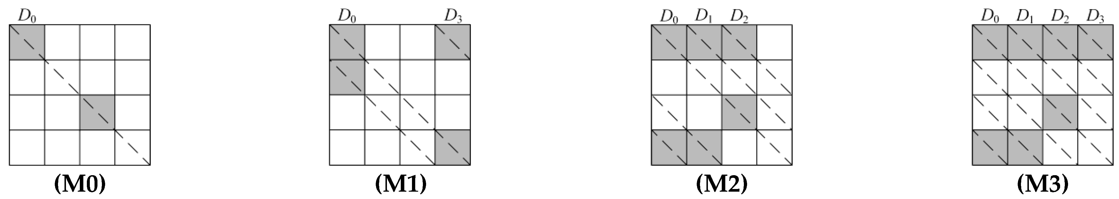
- A Dcor fault model that has been developed calls for fewer PCFCs than the existing model. Using the M1 model, for instance, [22] shows that although breaking AES–192 requires two PCFCs and 28 exhaustive searches, cracking AES–256 requires three PCFCs and 232 exhaustive searches. The proposed Dcor fault model, on the other hand, requires fewer PCFCs and thorough searches to recover AES–192. More specifically, recovering AES–192 only requires two PCFCs. The quantity of PCFCs and thorough searches needed for AES–256 relies on the use of different PCFCs. AES–256 can be cracked with 232 (or 216) exhaustive searches and two (or three) PCFCs, respectively.
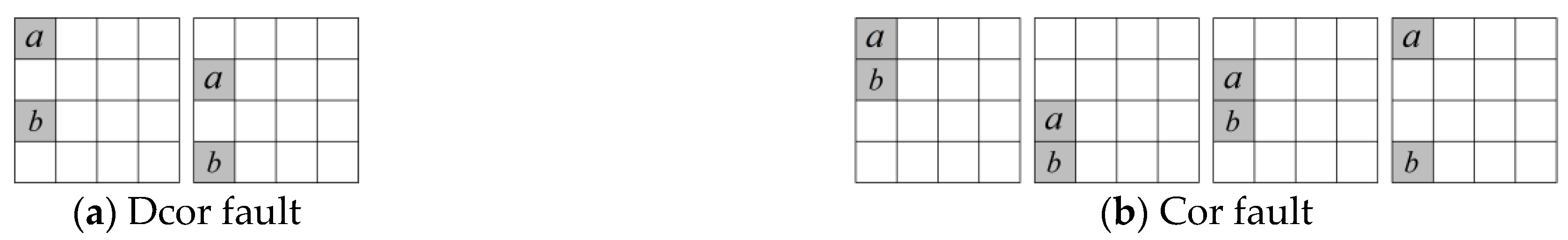
- The fault model with faults induced at Dcor of the state. The multi–byte fault is condensed into the Dcor fault, which is present in the first column of the state, as opposed to the earlier one [21,22]. The faults are dispersed throughout each state’s column in M0, M1, M2, and M3, which are more intricate. AES–128 is cracked in [13], and the authors presented a two–byte model with Dcor in the key schedule. However, the Dcor model proposed in this article deals with all variants of AES.
- The location of the fault induced is invariant. The location of the fault injection remains the same throughout the study, the conditions of fault induction (e.g., voltage, frequency) don’t need to be altered.
2. Description of AES
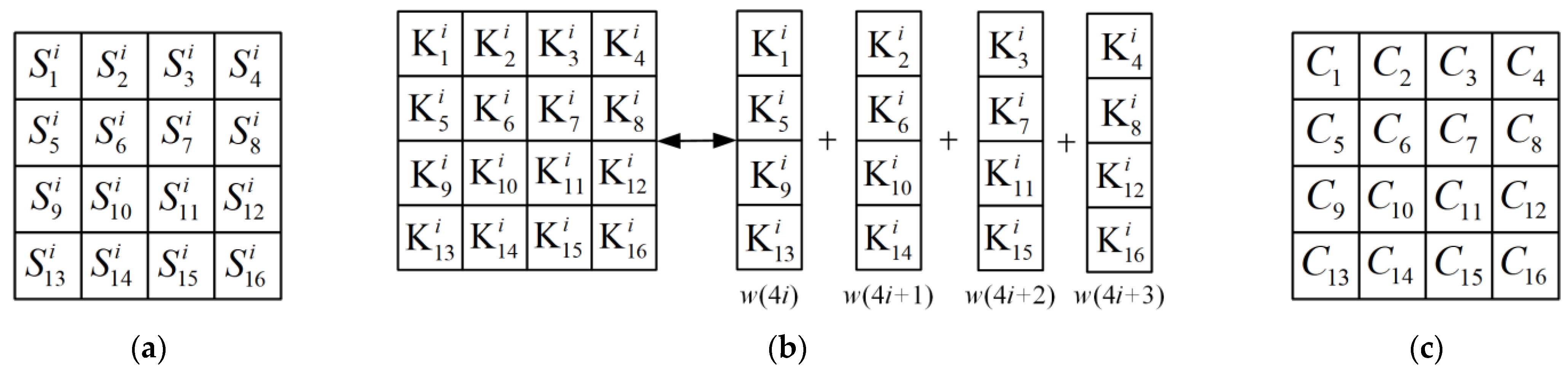
2.1. Notations
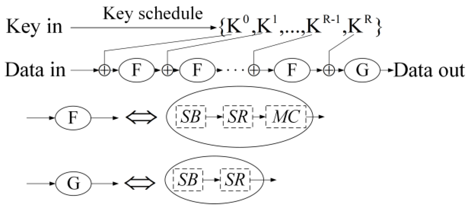
2.2. Encryption Process
- (a)
- SubByte (SB) Layer.
- (b)
- Diffusion Layer: it consists of two sublayers of ShiftRow (SR) and MixColumn (MC).
- (c)
- AddRoundKey (ARK) Layer.
3. DFA on AES
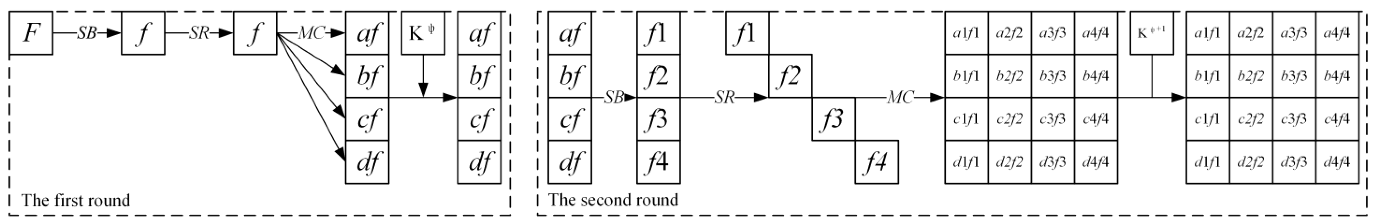
3.1. Fault Model Analysis
3.2. Fault Model
| Algorithm 1 Recovering the last round–key of AES. |
| Input: The PCFCs and . |
| Output: . |
| Construct and (j = 1, 5, 9, 13) and find , , , . |
| For the other three columns of , construct similar and solve them. |
| Return . |
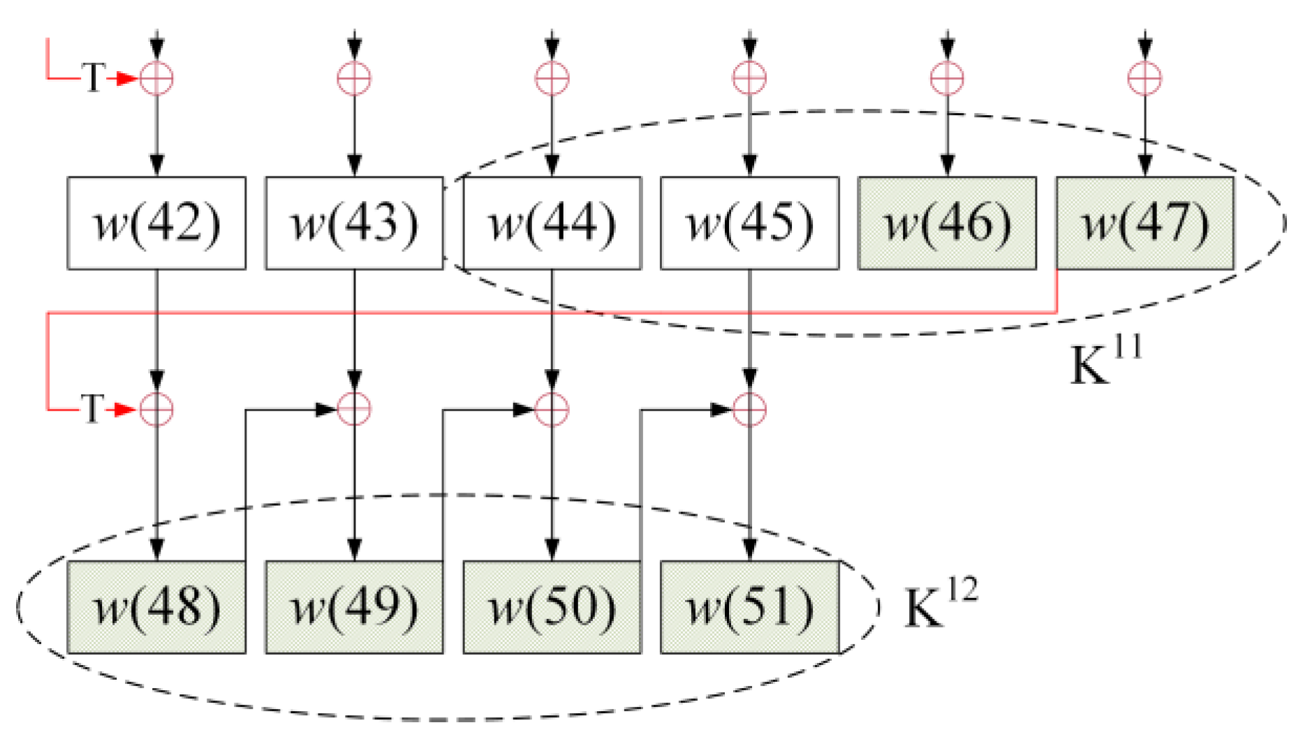
3.3. Proposed Attack on AES–192
| Algorithm 2 DFA on AES–192. |
| Input: The PCFCs . |
| Output: and the right part of . |
| 1. Construct and (j = 1, 5, 9, 13) and find , , , . |
| 2. For the other three columns of , construct similar and solve them. Finally, is obtained. |
| 3. Find the left part of with Equation (8). |
| 4. Find the PCFSs with Equation (9). |
| 5. With equations (11) and (12), {a, b, a’, b’} can be solved, and the right part of is known to the attacker. |
| Return and the right part of namely, {w(46), w(47), w(48), w(49), w(50), w(51)}. |
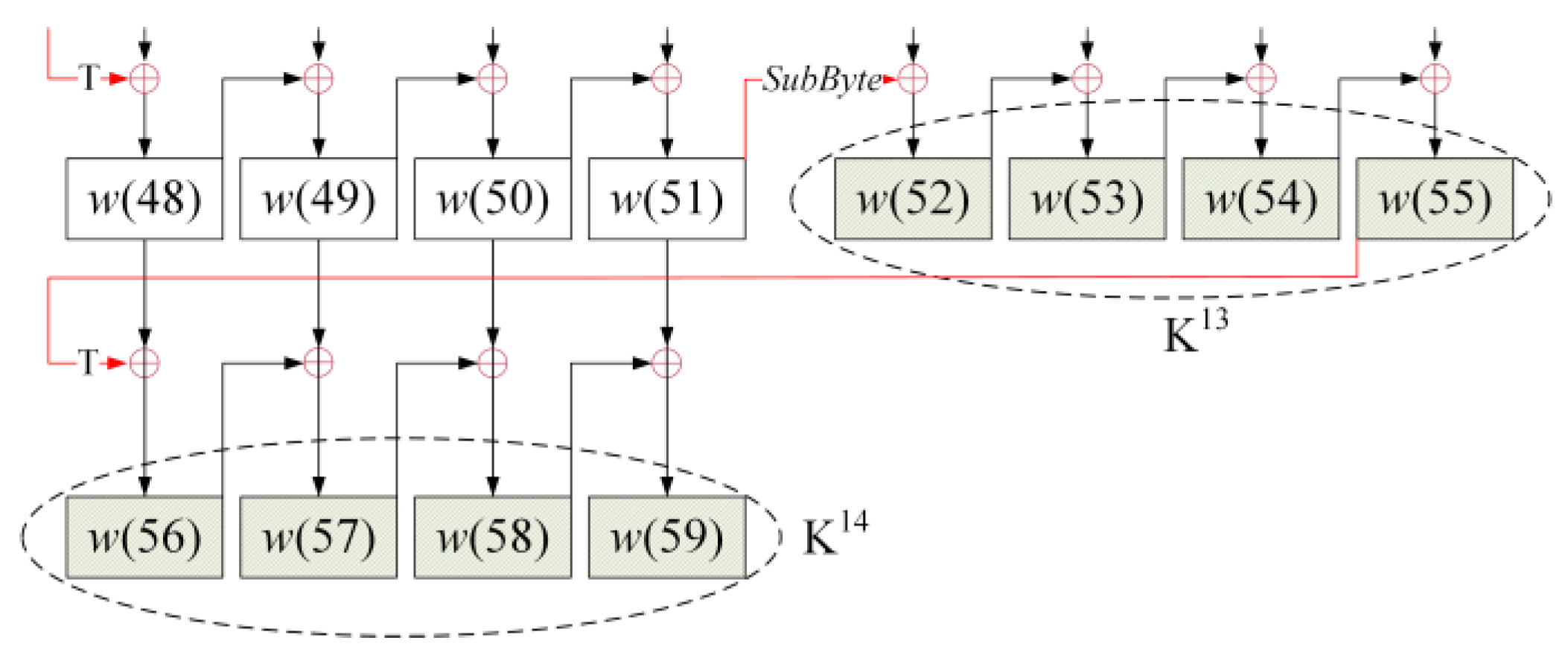
3.4. Proposed Attack on AES–256
| Algorithm 3 DFA on AES–256. |
| Input: i = 2, 3, and 4. |
| Output: K14 and K13. |
| 1. Find the last round–key K14 according to algorithm 1. |
| 2. Find the PCFSs with Equation (9). |
| 3. With equations (13) and (14), {a, b, a’, b’} cannot be solved. There are 232 exhaustive research to crack AES–256. |
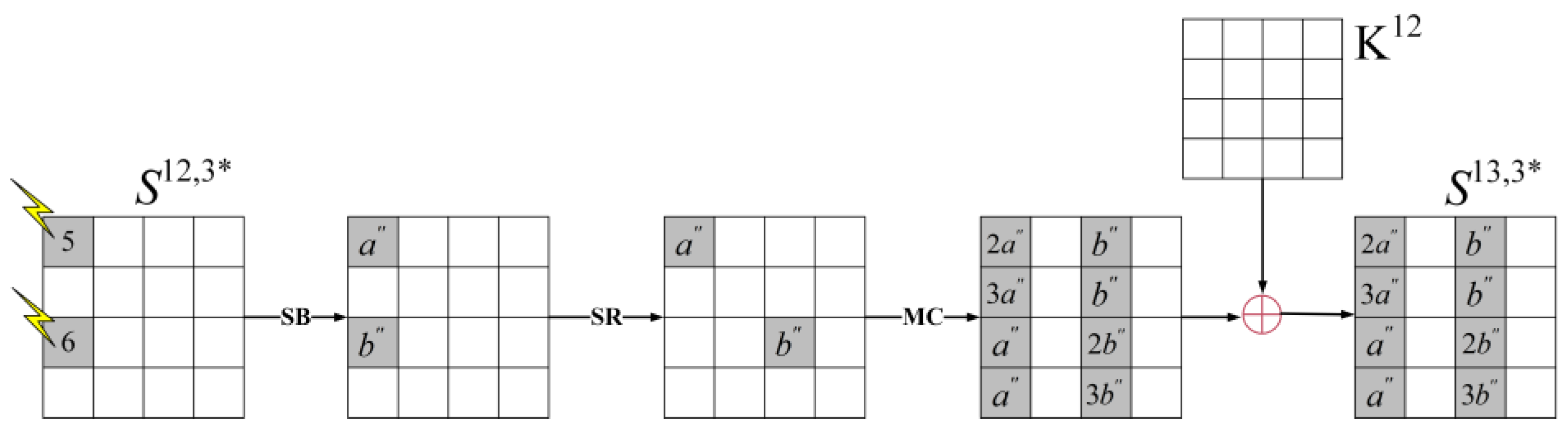
| 4. The range of exhaustive research could be reduced from 232 to 216 by injecting faults ‘5′ and ‘6′ at . |
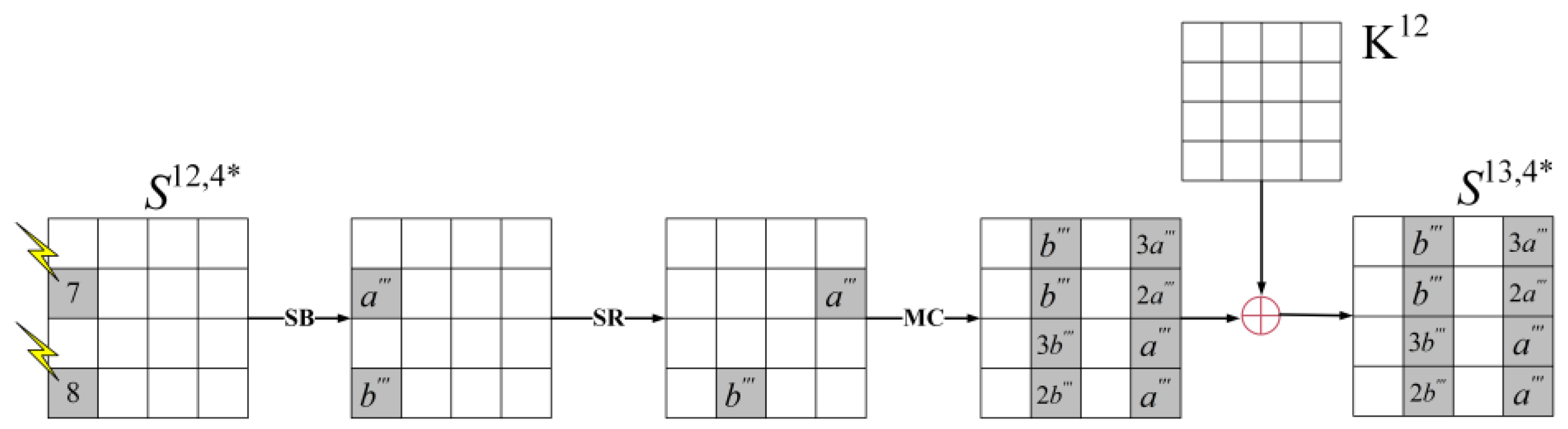
| 5. Based on the above conditions, the attacker injects faults ‘7′ and ‘8′ at . The unknow values {a, a’, a”, a‴, b, b’, b”, b‴} could be computed without exhaustive research. |
| Return K14 and K13. |
4. Simulation Result and Discussion
4.1. Experimental Result
4.2. Result Discussion
5. Conclusions
Author Contributions
Funding
Institutional Review Board Statement
Informed Consent Statement
Data Availability Statement
Acknowledgments
Conflicts of Interest
References
- Jain, R. Advanced Encryption Standard (AES). Federal Information Processing Standard; Springer: Berlin/Heidelberg, Germany, 2001. [Google Scholar] [CrossRef] [Green Version]
- Toughi, S.; Fathi, M.H.; Sekhavat, Y.A. An image encryption scheme based on elliptic curve pseudo random and Advanced Encryption System. Signal Process. 2017, 141, 217–227. [Google Scholar] [CrossRef]
- Shi, L. Design and Implementation of WiFi Security Intelligent Check-in System Encrypted by AES. J. Anhui Univ. Sci. Technol. Nat. Sci. 2019, 39, 56–59. [Google Scholar]
- Hashim, A.T.; Jabbar, A.K.; Hassan, Q.F. Medical Image Encryption Based on Hybrid AES with Chaotic Map. J. Physics Conf. Ser. 2021, 1973, 12–37. [Google Scholar] [CrossRef]
- Mehmood, G.; Khan, M.Z.; Abbas, S.; Faisal, M.; Rahman, H.U. An Energy-Efficient and Cooperative Fault- Tolerant Communication Approach for Wireless Body Area Network. IEEE Access 2020, 8, 69134–69147. [Google Scholar] [CrossRef]
- Scripcariu, L.; Burdia, D.; Diaconu, F. FPGA Synthesis of an AES Encoder Circuit for Vehicular Communication Networks. In Proceedings of the 2021 International Symposium on Signals, Circuits and Systems (ISSCS), Iasi, Romania, 15–16 July 2021; pp. 1–4. [Google Scholar] [CrossRef]
- Ramya, T.; Ramya, G.; Raju, K.; Ravi, J.; Verma, D. An Efficient AES Algorithm for Cryptography Using VLSI. ECS Trans. 2022, 107, 5605–5612. [Google Scholar] [CrossRef]
- Luminiţa, S.; Andreea-Elena, B.; Petre-Daniel, M. Improved C-Language Implementation of AES Algorithm for WSN. In Proceedings of the 2021 International Symposium on Signals, Circuits and Systems (ISSCS), Iasi, Romania, 15–16 July 2021; pp. 1–4. [Google Scholar] [CrossRef]
- Biham, E.; Shamir, A. Differential Fault Analysis of Secret Key Cryptosystems. In Proceedings of the International Cryptology Conference, Santa Barbara, CA, USA, August 15–19 1999; Springer: Berlin/Heidelberg, Germany, 1999; Volume 1924, pp. 513–525. [Google Scholar] [CrossRef] [Green Version]
- Chen, C.-N.; Yen, S.-M. Differential Fault Analysis on AES Key Schedule and Some Countermeasures. In Proceedings of the Australasian Conference on Information Security & Privacy, Wollongong, Australia, 9–11 July 2003; Springer: Berlin/Heidelberg, Germany, 2003; Volume 2727, pp. 118–129. [Google Scholar] [CrossRef]
- Kim, C.H.; Quisquater, J.-J. New Differential Fault Analysis on AES Key Schedule: Two faults are enough. In Proceedings of the Proceedings 8th IFIP WG 8.8/11.2 International Conference, London, UK, 8–11 September 2008; (CARDIS2008); Volume 5189, pp. 48–60. [Google Scholar] [CrossRef] [Green Version]
- Ali, S.S.; Mukhopadhyay, D. Differential Fault Analysis of AES–128 Key Schedule Using a Single Multi-byte Fault. In Proceedings of the International Conference on Smart Card Research and Advanced Applications, Leuven, Belgium, 14–16 September 2011; Springer: Berlin/Heidelberg, Germany, 2011; pp. 50–64. [Google Scholar] [CrossRef] [Green Version]
- Zhang, J.; Wu, N.; Li, J.; Zhou, F. A novel differential fault analysis using two-byte fault model on AES Key schedule. IET Circuits Devices Syst. 2019, 13, 661–666. [Google Scholar] [CrossRef]
- Kim, C.H. Improved Differential Fault Analysis on AES Key Schedule. IEEE Trans. Inf. Forensics Secur. 2012, 7, 41–50. [Google Scholar] [CrossRef]
- Floissac, N.; L’Hyver, Y. From AES–128 to AES–192 and AES–256, How to Adapt Differential Fault Analysis Attacks on Key Expansion. In Proceedings of the 2011 Workshop on Fault Diagnosis and Tolerance in Cryptography, Nara, Japan, 28 September 2011; pp. 43–53. [Google Scholar] [CrossRef]
- Kiranmayee, T.S.; Maniraj, S.P.; Thakur, A.; Bhagyashree, M.; Gupta, R. Analyzing DFA Attack on AES–192. In Lecture Notes on Data Engineering and Communications Technologies; Springer: Berlin/Heidelberg, Germany, 2018; Volume 31, pp. 211–218. [Google Scholar] [CrossRef]
- Moradi, A.; Shalmani, M.T.M.; Salmasizadeh, M. A Generalized Method of Differential Fault Attack Against AES Cryptosystem. In Proceedings of the International Workshop on Cryptographic Hardware and Embedded Systems, Yokohama, Japan, 10–13 October 2006; Springer: Berlin/Heidelberg, Germany, 2006; Volume 4249, pp. 91–100. [Google Scholar] [CrossRef] [Green Version]
- Han, L.; Wu, N.; Ge, F.; Zhou, F.; Wen, J.; Qing, P. Differential Fault Attack for the Iterative Operation of AES–192 Key Expansion. In Proceedings of the 2020 IEEE 20th International Conference on Communication Technology (ICCT), Nanning, China, 28–31 October 2020; IEEE: Piscataway, NJ, USA; pp. 1156–1160. [Google Scholar] [CrossRef]
- Li, W.; Gu, D.; Wang, Y.; Li, J.; Liu, Z. An Extension of Differential Fault Analysis on AES. In Proceedings of the International Conference on Network and System Security, Los Alamitos, CA, USA, 19 October 2009; IEEE Computer Society: Washington, DC, USA, 2009; pp. 443–446. [Google Scholar] [CrossRef]
- Piret, G.; Quisquater, J.-J. A Differential Fault Attack Technique against SPN Structures, with Application to the AES and Khazad. In Proceedings of the International Workshop on Cryptographic Hardware and Embedded Systems, Cologne, Germany, 8–10 September 2003; Springer: Berlin/Heidelberg, Germany, 2003; Volume 2779, pp. 77–88. [Google Scholar] [CrossRef] [Green Version]
- Saha, D.; Mukhopadhyay, D.; Chowdhury, D.R. A Diagonal Fault Attack on the Advanced Encryption Standard. Cryptol. Eprint Arch. 2009. Report2009/581. [Google Scholar]
- Kim, C.H. Differential fault analysis of AES: Toward reducing number of faults. Inf. Sci. 2012, 199, 43–57. [Google Scholar] [CrossRef] [Green Version]
- Prior, S.; Maciver, D.; Forsyth, K.; Walsh, M.; Meiklejohn, A.; Irvine, L. Differential Fault Analysis of the Advanced Encryption Standard Using a Single Fault. Community Ment. Health J. 2013, 49, 658–667. [Google Scholar] [CrossRef] [PubMed]
- Barenghi, A.; Bertoni, G.M.; Breveglieri, L.; Pellicioli, M.; Pelosi, G. Low voltage fault attacks to AES. In Proceedings of the 2010 IEEE International Symposium on Hardware-Oriented Security and Trust (HOST), Anaheim, CA, USA, 14 June 2010; pp. 7–12. [Google Scholar] [CrossRef]
- Kim, C.H. Differential Fault Analysis against AES–192 and AES–256 with Minimal Faults. In Proceedings of the 2010 Workshop on Fault Diagnosis and Tolerance in Cryptography, Santa Barbara, CA, USA, 21 August 2010; IEEE Computer Society: Washington, DC, USA; pp. 3–9. [Google Scholar] [CrossRef]
- Liao, N.; Cui, X.; Liao, K.; Wang, T.; Yu, D.; Cui, X. Improving DFA attacks on AES with unknown and random faults. Sci. China Inf. Sci. 2017, 60, 166–179. [Google Scholar] [CrossRef]
- Liu, Y.; Cui, X.; Cao, J.; Zhang, X. A hybrid fault model for differential fault attack on AES. In Proceedings of the 2017 IEEE 12th International Conference on ASIC (ASICON), Guiyang, China, 25–28 October 2017; IEEE: Piscataway, NJ, USA, 2017; pp. 784–787. [Google Scholar] [CrossRef]
- Long, M.; Kong, M.; Long, S.; Zhang, X. An Improved Differential Fault Analysis on Block Cipher KLEIN-64. Comput. Mater. Contin. 2020, 65, 1425–1436. [Google Scholar] [CrossRef]
- Xiao, H.; Wang, L. The differential fault analysis on block cipher KLEIN-96. J. Inf. Secur. Appl. 2022, 67, 103205. [Google Scholar] [CrossRef]
- Anand, R.; Siddhanti, A.; Maitra, S. Differential Fault Attack on SIMON with Very Few Faults; Progress in Cryptology-INDOCRYPT. In Proceedings of the 19th International Conference on Cryptology in India, New Delhi, India, 9–12 December 2018; pp. 107–119. [Google Scholar] [CrossRef]
- Zhang, J.; Wang, J.; Bin, G.; Li, J. An efficient differential fault attack against SIMON key schedule. J. Inf. Secur. Appl. 2022, 66, 103155. [Google Scholar] [CrossRef]
- Nalla, V.; Sahu, R.A.; Saraswat, V. Differential Fault Attack on SIMECK. In Proceedings of the Third Workshop on Cryptography and Security in Computing Systems, Prague, Czech Republic, 20 January 2016; pp. 45–48. [Google Scholar] [CrossRef]
- Le, D.-P.; Lu, R.; Ghorbani, A.A. Improved fault analysis on SIMECK ciphers. J. Cryptogr. Eng. 2022, 12, 169–180. [Google Scholar] [CrossRef]


| Type | Encryption Rounds (R) | Key Schedule Rounds |
|---|---|---|
| AES–128 | 10 | 10 |
| AES–192 | 12 | 8 |
| AES–256 | 14 | 7 |
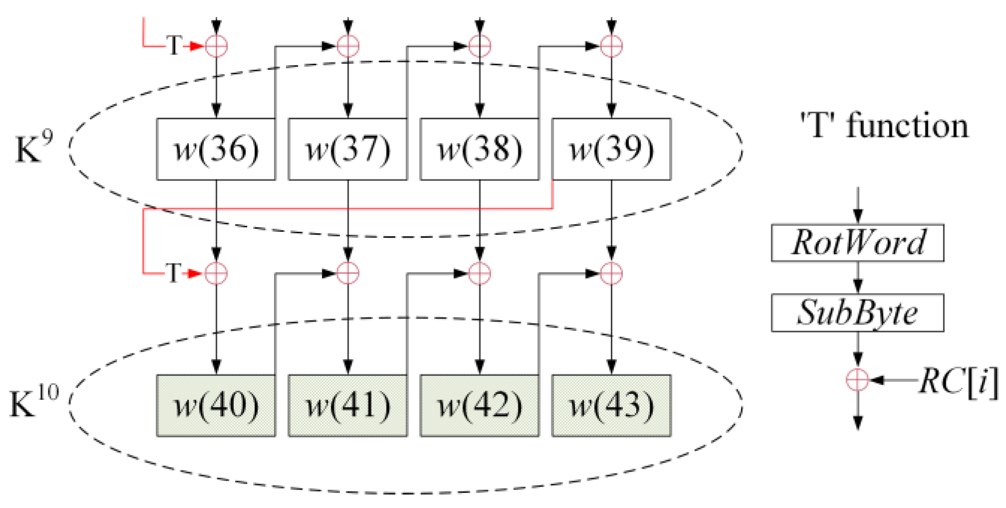
| i | 1 | 2 | 3 | 4 | 5 | 6 | 7 | 8 | 9 | 10 |
|---|---|---|---|---|---|---|---|---|---|---|
| RC[i] | 01 | 02 | 04 | 08 | 10 | 20 | 40 | 80 | 1B | 36 |
| τ | the First Round χ | the Second Round χ | the Third Round χ | Is the Result Available? |
|---|---|---|---|---|
| 1 | 4 | 16 | 16 | Y |
| 2 | 8 | 16 | 16 | Y |
| 3 | 12 | 16 | 16 | Y |
| 4 | 16 | 16 | 16 | Y |
| 5 | 16 | 16 | 16 | N |
| … | … | … | … | … |
| 15 | 16 | 16 | 16 | N |
| 16 | 16 | 16 | 16 | N |
| Type | Ref | Fault Model | Fault Round | No. of Faults | Exhaustive Search |
|---|---|---|---|---|---|
| AES–128 | [13] | Dcor | 9 | 2 | 1 |
| [21] | M0 | Between 7 and 8 | 4 | 1 | |
| M1 | Between 7 and 8 | 2 | 1 | ||
| M2 | Between 7 and 8 | 1 | 1 | ||
| [22] | M1 | Between 7 and 8 | 2 | 1 | |
| M2 | Between 7 and 8 | 3 | 1 | ||
| [26] | Multi–fault | 9 | ≈2.17 | 1 | |
| Our work | Dcor | 8 | 2 | 1 | |
| AES–192 | [19] | Method1 | 10 and 11 | 12 | 1 |
| Method2 | 10 and 11 | ≈3000 | 1 | ||
| [22] | M1 | Between 9 and 10 | 2 | 28 | |
| M2 | Between 9 and 10 | 3 | 232 | ||
| Our work | Dcor | 10 | 2 | 1 | |
| AES–256 | [19] | Method1 | 12 and 13 | 12 | 1 |
| Method2 | 12 and 13 | ≈3000 | 1 | ||
| [22] | M1 | Between 11 and 12 | 3 | 232 | |
| M2 | Between 11 and 12 | 4 | 1 | ||
| Our work | Dcor | 12 | 2 3 4 | 232 216 1 |
Disclaimer/Publisher’s Note: The statements, opinions and data contained in all publications are solely those of the individual author(s) and contributor(s) and not of MDPI and/or the editor(s). MDPI and/or the editor(s) disclaim responsibility for any injury to people or property resulting from any ideas, methods, instructions or products referred to in the content. |
© 2023 by the authors. Licensee MDPI, Basel, Switzerland. This article is an open access article distributed under the terms and conditions of the Creative Commons Attribution (CC BY) license (https://creativecommons.org/licenses/by/4.0/).
Share and Cite
Wan, X.; Zhang, J.; Cheng, S.; Wu, W.; Wang, J. A Novel DFA on AES: Based on Two–Byte Fault Model with Discontiguous Rows. Appl. Sci. 2023, 13, 8282. https://doi.org/10.3390/app13148282
Wan X, Zhang J, Cheng S, Wu W, Wang J. A Novel DFA on AES: Based on Two–Byte Fault Model with Discontiguous Rows. Applied Sciences. 2023; 13(14):8282. https://doi.org/10.3390/app13148282
Chicago/Turabian StyleWan, Xusen, Jinbao Zhang, Shi Cheng, Weixiang Wu, and Jiehua Wang. 2023. "A Novel DFA on AES: Based on Two–Byte Fault Model with Discontiguous Rows" Applied Sciences 13, no. 14: 8282. https://doi.org/10.3390/app13148282