Article

Developing an Active Microfluidic Pump and Mixer Driven by AC Field-Effect-Mediated Induced-Charge Electro-Osmosis of Metal–Dielectric Janus Micropillars: Physical Perspective and Simulation Analysis

1
School of Electronics and Control Engineering, Chang’an University, Xi’an 710064, China
2
School of Mechatronics Engineering, Harbin Institute of Technology, Harbin 150001, China
3
School of Continuing Education, Chang’an University, Xi’an 710064, China
4
School of Energy and Electrical Engineering, Chang’an University, Xi’an 710064, China
*
Authors to whom correspondence should be addressed.
These authors contributed equally to this work.
Appl. Sci. 2023, 13(14), 8253; https://doi.org/10.3390/app13148253
Submission received: 18 June 2023 / Revised: 13 July 2023 / Accepted: 13 July 2023 / Published: 16 July 2023
(This article belongs to the Topic Advances in Microfluidics and Lab on a Chip Technology)

Abstract

:

Featured Application

The Janus AC-FFET technique proposed herein can be effectively applied to the development of active microfluidic pumps and mixers driven by pure ICEO, even in the absence of an external moving element, in which both the horizontal pump-flow component, ux, and the transversal mixing flow component, uy, are created by the induced-charge electrokinetic effect.

Abstract

We propose herein a novel microfluidic approach for the simultaneous active pumping and mixing of analytes in a straight microchannel via the AC field-effect control of induced-charge electro-osmosis (ICEO) around metal–dielectric solid Janus cylinders of inherent inhomogeneous electrical polarizability immersed in an electrolyte solution. We coin the term “Janus AC flow field-effect transistor (Janus AC-FFET)” to describe this interesting physical phenomenon. The proposed technique utilizes a simple device geometry, in which one or a series of Janus microcylinders are arranged in parallel along the centerline of the channel’s bottom surface, embedding a pair of 3D sidewall driving electrodes. By combining symmetry breaking in both surface polarizability and the AC powering scheme, it is possible, on demand, to adjust the degree of asymmetry of the ICEO flow profile in two orthogonal directions, which includes the horizontal pump and transversal rotating motion. A comprehensive mathematical model was developed under the Debye–Hückel limit to elucidate the physical mechanism underlying the field-effect-reconfigurable diffuse-charge dynamics on both the dielectric and the metal-phase surfaces of the Janus micropillar. For innovation in applied science, an advanced microdevice design integrating an array of discrete Janus cylinders subjected to two oppositely polarized gate terminals is recommended for constructing an active microfluidic pump and mixer, even without external moving parts. Supported by a simulation analysis, our physical demonstration of Janus AC-FFET provides a brand-new approach to muti-directional electro-convective manipulation in modern microfluidic systems.

1. Introduction

The stirring of two or multiple co-flowing samples is critical and challenging for controlled chemical reactions, thermal management, drug discovery, and disease diagnostics at the micrometer scale [1,2,3]. Numerous approaches have been explored in the last two decades to promote analyte mixing within confined microfluidic channels, including either active or passive mixing devices, taking into consideration the driving mechanism based upon which they operate [4,5]. Because passive stirring expands the thickness of the two-phase contact interface, increases the time of interfacial mass exchange, and disturbs the laminar streamlines between parallel buffer solutions by inserting solid obstructions into the microchannel, it completely relies on the molecular-diffusion effect or chaotic advection [6]. In stark contrast, active micromixers exploit an external energy input to cause dynamic fluid motion and enhance the mixing performance, as in acoustic streaming [7], magnetic actuation [8], and electrokinetic (EK) forcing [9].
In particular, electro-hydrodynamics (EHDs) have been extensively investigated in microsystems to realize the flexible manipulation of leaky dielectric working fluid or nanoparticle samples monodispersed within it [10,11,12,13,14,15,16,17,18]. Within quasi-electrostatic limits, the common trait of EHDs manifests as an action of the local electric field on the space-charge density it induces to impart a net electrostatic body force and actuate the motion of the target medium via structural polarization [19]. This occurs in the so-called Ohmic model under an electroneutrality constraint [20], which is often accompanied by electrochemical polarization at charged solid/liquid interfaces [21,22,23,24,25]. In particular, the recent advances in microelectronic processing techniques have facilitated an easy way for compact metallic microelectrode arrays to be patterned and embedded into microfluidic devices, providing precious opportunities to exert ponderomotive Coulomb and dielectric forces directly on the working fluid—even during exposure to external AC forcing—on account of the field-induced features of the electrical charges involved in nonlinear electrokinetics [26]. Unlike traditional forms of linear EK, such as unidirectional DC electro-osmotic (EO) plug-like pump-fluid motion [27,28,29], nonlinear EHD survives well and appears as a series of micro-vortices of variable rotating directions after time-averaging operations under AC actuation [30,31,32,33,34,35]. In this way, nonlinear EK effects, in which the electrical driving force scales nonlinearly with the applied voltage, tend to enable more flexible control of localized flow behavior and are suitable for some intriguing microfluidic applications, such as medium transport [36,37,38,39,40], analyte mixing [41,42,43], and sample enrichment [31,44,45,46,47] in confined channels. Considering the high degree of freedom controllability achieved by tuning the magnitude, phase sequence, and angular frequency of the imposed AC voltage signal, both AC electrothermal (ACET)-induced flow and induced-charge electro-osmosis (ICEO) have received increasing attention from the microfluidics community, serving as the two most classical examples of nonlinear AC electro-hydrodynamics.
Unlike ACET, which behaves as a type of bulk electroconvection originating from induced space charges under Maxwell–Wagner structural polarization, the induced-charge electrokinetic (ICEK) phenomenon arises due to voltage-driven diffuse-charge dynamics around ideally or even weakly polarizable solid surfaces immersed in conducting fluids [48]. The ICEK occurs when a background electric field E induces a Debye screening cloud at polarizable solid/liquid interfaces and subsequently forces its own induced bipolar diffuse charges inside the induced double layer (IDL) into an active ICEO streaming flow. As the characteristic thickness of IDL containing excessive mobile counterions shrinks with the ionic strength, ICEO is especially efficient for manipulating low-conductivity liquid solutions [49].
The adjustment of asymmetry in the material composition of polarizable solid objects serves as a simple way of regulating the mechanical behavior of ICEO. For example, a typical scenario in which ICEO is engendered is the evolution of a quadrupolar ICEO vortex flow field in opposite rotating directions next to an ideally polarizable metal cylinder, usually placed in a background low-frequency AC electric field [50]. Based on this device geometry, Paustian et al. [51] recently suggested the use of an array of metal–dielectric Janus micropillars of asymmetric interfacial polarizability to break the symmetry of a classical ICEO vortex flow field next to conducting posts so that an external AC-voltage difference applied across the array of discrete Janus posts drives unidirectional ICEO flow along the channel length direction, allowing a net pump motion perpendicular to the imposed electric field.
In our current work, we developed an effective microfluidic technology of dual functionality in the simultaneous active pumping and mixing of analytes via pure ICEO without any external moving parts, as shown in Figure 1A,B. The fully automated microfluidic pump and mixer driven by ICEO are achievable by a delicate combination of horizontal flow symmetry breaking around an originally unbiased metal–dielectric Janus cylinder (Figure 1C) and transversal counterpart via the AC field-effect control of ICEO (Figure 1D,E). By applying a biased AC gate voltage to the metal phase of the central Janus micropillar placed between a pair of 3D sidewall driving electrodes (DE) in a straight microchannel (Figure 1A), a new net rotating behavior uy was created for lateral ICEO streaming parallel to the applied field lines due to the AC field-effect flow control (Figure 1D,E), apart from the existing horizontal pump motion ux due to the symmetry breaking in the ICEO caused by the inhomogeneous polarizability of the Janus pillar along the channel’s length (Figure 1C).
Therefore, we coin the term “Janus AC flow-field-effect transistor (Janus AC-FFET)” to highlight its unique feature of the controllable asymmetry of the ICEO flow profile in two orthogonal directions (Figure 1). It is worth mentioning that Janus AC-FFET is different from the traditional AC field-effect control of standard ICEO on uniform solid surfaces, since symmetry breaking in ICEO convection can only be realized along one specific orientation. Recently, Velev et al. [52] demonstrated how various semiconductor diodes form a new category of self-propelling particles and pumps in microfluidic systems. The energy is supplied by a global external AC electric field. A DC voltage difference is then created between the electrodes of each diode due to the rectification of the global AC field. The uniform electric field between the electrodes gives rise to stable electro-osmotic flow, which can propel the floating diodes or pump the surrounding liquid. A subsequent article from the same group [53] presented detailed results and a discussion of the fluid pumping and flow-behavior control with semiconductor diodes subjected to external AC electric fields. The diodes were fixed alongside the insulating channel walls and, depending on their mutual orientation, could work as pumps or mixers. The parameters that regulated the fluid flow were identified, and their effects were studied numerically.
Although the present work and the relevant study by Velev et al. used an anisotropic solid object to actuate biased electrohydrodynamic fluid motion, the underlying physical mechanism was completely different. Our proposed idea of the Janus AC-FFET is based upon time-averaged nonlinear induced-charge electro-osmosis at polarizable metal/electrolyte interfaces with symmetric breaking in the flow profile along two orthogonal directions, with the potential to achieve the simultaneous pumping and mixing of analytes in microfluidic channels, while remotely powered microfluidic devices embedding miniature diodes are intrinsically created by linear electro-osmosis acting on a native electrical double layer under a local DC voltage rectified from the globally applied AC electric field [52,53]. More importantly, the research group led by Velev has made a series of breakthrough scientific achievements in the field of electrokinetic microfluidics in the past two decades [54,55,56,57,58,59,60,61].
The standard model of ICEO was proposed by Squires and Bazant in a pioneering study [62]. In the mathematical derivation of the standard model, the polarizable solid surface in contact with the electrolyte solution is assumed to be a perfect metal conductor of an equal body potential when subjected to a background DC or low-frequency AC electric field. Thus, it may be difficult for the standard model to describe the phenomenon of ICEK adjacent to non-metallic solid objects. To investigate the Janus AC-FFET in detail, under the approximation of a thin IDL and a small IZP, starting from the leaky dielectric theory, we derived a rigorous macroscopic mathematical model that can capture inhomogeneous electrochemical polarization and time-averaged ICEO slipping at the pillar/electrolyte interfaces on both the metal- and dielectric-phase surface of the Janus post. Considering the high impedance of the dielectric phase, the capacitive charging of IDL on its insulating surface is usually at least two orders of magnitude weaker than that on the conducting surface, so it can be safely disregarded in most situations [63]. However, in the transition region between the metal and the dielectric phase, there is appreciable ICEO slipping velocity, which is identical to the strong ICEO jet observed around sharp dielectric corners [64,65]. That is, the standard model of ICEK may malfunction when a dielectric solid phase with sharp boundaries is involved in microfluidic channels. In this sense, by resolving the phenomenon of ICEO streaming on solid surfaces with electrical polarizability, our physical description of the ICEO is more accurate than the standard model obtained by the linear RC circuit theory on perfect conductors. It is worth noting that the standard model is generally correct when mere metal conductors are utilized to actuate ICEO convection under the Debye–Hückel limit. Armed with this utilitarian calculation model, it is possible to explore the basic physics underlying the Janus AC-FFET.
Specifically, AC field-effect flow control through the metal-phase gate voltage of Janus pillars immersed in an electrolyte solution allows Janus AC-FFET to generate arbitrary symmetry breaking in the lateral flow pattern of ICEO whirlpools to produce a net transversal rotating motion uy, which already possesses a horizontal unidirectional pump motion ux, caused by inhomogeneous material composition. Furthermore, as also revealed by our numerical analysis, the synergy in controllable ICEO flow behavior in the two orthogonal directions ux and uy can be fully exploited to realize an advanced microfluidic pump and mixer, which integrates an array of discrete Janus pillars sequentially subjected to two oppositely-polarized gate terminals for the active pumping and convective stirring of two stratified liquid contents without any external moving elements (Figure 1A). The proposed method of the Janus AC-FFET is intended to guide the smart design of flexible electrokinetic frameworks embedding inhomogeneous microstructures for active on-chip analyte treatment in multiple flow directions.

2. Materials and Methods

2.1. Basic Device Geometry of Microfluidic Pump and Mixer Utilizing Janus AC-FFET

On the basis of Janus AC-FFET, we carried out a comprehensive simulation analysis of the flow pattern of ICEO near an individual metal–dielectric Janus microcylinder, as well as of the performance of a highly integrated micropump and mixer arranging an array of discrete Janus pillars (Figure 1). The basic structure of a typical ICEO microfluidic device with circular Janus posts, which has dual functionality in simultaneous electro-convective pumping and mixing of incoming chemical analyte, is schematically shown in Figure 1A. The active microdevice has three branch channels, including two liquid inlets and one liquid outlet for sample discharge, which each have direct connection with three reservoirs (not shown). The entrance of the straight main channel of length LC and width WC has a Y-shaped geometry (Figure 1A).
A pair of 3D Ag-PDMS conducting plates are embedded into both sidewalls of the main-channel of height HC, serving as the driving electrodes (DE) powered by an AC voltage supply. Moreover, a series of metal–dielectric Janus microcylinders of radius R and a neutral metal phase angle α = 180° with sequentially reversed gate-voltage polarity are disposed along the centerline of channel bottom surface parallel to the sidewall DE (Figure 1B). The polar interface bisecting the two distinct hemispheres of each Janus pillar is perpendicular to channel sidewalls, with an azimuth angle θ = 90° relative to the horizontal x-axis (Figure 1B).
In the numerical simulation, the fluid channel is filled with aqueous electrolyte of electric conductivity σf = 0.001 S·m−1 and permittivity ε = 80ε0. The left upstream inlet releases fresh liquid solution of same electrical properties, which contains the target fluorescein nanoparticles for simultaneous electrokinetic transport and stirring driven by ICEO convection, while the right entrance merely provides pure electrolyte solution without any analytes. No external moving parts or syringe pumps are needed to achieve effective fluid mixing in the microdevice applying Janus AC-FFET due to net pump-flow component of ICEO eddies induced naturally around non-uniformly polarized solid surfaces, such as Janus micropillars used herein (Figure 1C).
Once we turn on the multichannel sinewave generator, it imposes a time-harmonic driving voltage of VDcos(2πft) to the pair of 3D DE plates on both channel sidewalls, and an in-phase AC gate signal of either VG1cos(2πft) or VG2cos(2πft) of same oscillating frequency but distinct gate-voltage amplitude to the metal phase of the array of discrete Janus micropillars. Here, VD is the amplitude of AC-driven voltage, and VG1 and VG2 are those of AC gate voltage applied to the odd and even sequence of the repeating Janus posts when observing from upstream to downstream, respectively (Figure 1A). The f and ω = 2πf are the linear and angular field frequencies, respectively, of the applied voltage. In most situations, VG1 and VG2 have opposite polarity for adjacent pillars. The specific bias degrees of gate voltage βodd = (VG1 − 0.5VD)/0.5VD and βeven = (VG2 − 0.5VD)/0.5VD are equal in magnitude but opposite in sign with βodd = −βeven for odd- and even-numbered Janus micropillars in the discrete arrangement.
With the assistance of AC field-effect flow control, two counter-rotating ICEO whirlpools with adjustable asymmetry in lateral flow profile are created selectively on the conducting surface of each Janus post arranged within the microchannel by regulating the gate voltage bias (Figure 1D,E), which perpendicularly intersects with the net electrokinetic pump’s flow component induced by the originally symmetric ICEO eddies themselves (Figure 1C). This can potentially result in a helical analyte-flow trajectory toward channel outlet, such that the diffusion-phase interface between the two stratified streams released from two inlets can be simultaneously pumped, rotated, and stretched actively, mainly under the ICEO, without the need for external moving parts, such as syringe pumps.
When the central Janus pillar floats in electrostatic potential or is subjected to a non-biased AC powering scheme, with β = 0 corresponding to VG = VD/2 (Figure 1C), two symmetric ICEO whirlpools in counter-rotating directions appear on its conducting side, and there is no evident electroconvection on the dielectric surface. This flow-symmetry breaking leads to a net pump-fluid motion along the channel length perpendicular to the applied electric field (Figure 1C), while still lacking a definite transversal perturbation umix for reinforcement of sample mixing. To address this issue, a positively (negatively) biased gate voltage VG1 > VD/2 (VG2 < VD/2) attracts more anions (cations) than cations (anions) within the bipolar IDL induced at metal/electrolyte interface on pillar surface, and the action of downward background electric field E on its own induced diffuse screening cloud produces two asymmetric lateral micro-eddies with an explicit upward (downward) mixing-flow component umix of an ICEO origin parallel to the field lines in addition to the pre-existing pump effect upump toward downstream, as shown in Figure 1D and Figure 1E, respectively. To this end, field-effect flow control via a biased gate-voltage supplement enriches the ICEO flow modes near metal–dielectric Janus post of inhomogeneous electrical polarizability.
More importantly, from the perspective of applied science, the coexistence of upump and umix in two mutually perpendicular directions greatly facilitates the development of a utilitarian paradigm of fully active ICEO microfluidic pump and mixer via Janus AC-FFET. As shown in Figure 1A, a series of gating Janus micropillars with an equal inter-pillar separation LG rather than a single separation (Figure 1C–E)) are configured in sequence along channel floor. In this highly integrated device architecture, as asymmetric ICEO vortices with opposite transversal streaming directions umix (Figure 1D,E) alternate along the axial path of unidirectional electrokinetic pump flow upump, transient rotating direction of the diffusion-phase interface can be artificially governed by imposing a desired gate polarity on the metal phase of each Janus post in the array. As a result, as long as adjacent Janus pillars are equally but oppositely polarized with βodd = −βeven, it is possible to realize a moderate repeating distance cycle for bidirectional electrochemical polarization of the transversal ICEO disturbance. Therefore, better device efficiency can be obtained in terms of dual functionality in simultaneous electro-convective transport and mixing of fluid samples by Janus AC-FFET than the traditional case driven by standard ICEO around a floating Janus object under no-bias AC actuation, where external syringe pumps are necessary for continuous sample injection.

2.2. Mathematical Model of Active Sample Transport and Stirring via Janus AC-FFET

  • (a) AC electric field
The entire calculation domain can be divided into four correlated subregions, including the liquid volume, the dielectric and metallic phase of the Janus pillar, and the bipolar IDL formed at the polarizable solid/electrolyte interface. The first three are considered bulk zones, while the latter is treated equivalently by interfacial conjugating conditions of an abrupt voltage drop across Debye screening layer according to conservation of charge flux. In the quasi-electrostatic limit, local electroneutrality approximation (LEA) can be safely invoked for a lossy dielectric medium containing sufficient charge carriers, so the electrical potential field ϕ ˜ within all the three bulk subdomains is governed by electric current continuity in a sinusoidal steady state:
( ( σ i + j ω ε i ) ϕ ˜ i ) = 0   for   i   =   f ,   d ,   m     Ω f Ω d Ω m
where the subscripts i = f, d, and m stand for the working fluid, dielectric phase, and metal phase of the Janus micropillar of inhomogeneous polarizability (Figure 1F). The σ and ε are the electric conductivity and real permittivity, respectively, of corresponding medium bulk. Under the assumption of uniform electrical properties in every subdomain, control equations of the AC electric fields are reduced to Laplace equations with zero induced space charge:
2 ϕ ˜ i = 0   for   i   =   f ,   d ,   m     Ω f Ω d Ω m
At the structural interface between aqueous electrolyte and dielectric phase of the Janus cylinder, the IZP across the IDL is tightly related to the normal field intensity in the bulk fluid immediately outside the thin boundary layer according to charge conservation:
( σ f + j ω ε f ) ϕ ˜ f n = j ω C 0 ( ϕ ˜ f ϕ ˜ d )     T FGH T KLM
ε d ϕ ˜ d n = C 0 ( ϕ ˜ f ϕ ˜ d )     T FGH T KLM
where we apply the core idea of classical linear RC-circuit theory of ICEK on ideally polarizable conducting solid surfaces to describe field-induced Debye screening on weakly polarizable dielectric object, simply by replacing the original Ohmic current with the displacement current flowing across the dielectric matrix. This is correct on the macroscopic scale under the Debye–Hückel limit, as demonstrated by our previous investigation on the effect of sharp corners of dielectric obstacles on resulting swirling ICEO streamlines induced along channel sidewalls. The C0 = CD/(1 + δ) denotes the total IDL capacitance, which comprises the diffuse layer capacity CD = εf/λD of mobile counterions and the Stern layer capacity CS of immobile ions connected in series, in terms of the double-layer thickness λD = (1/σ1)1/2 and surface capacitive impedance ratio of δ = CD/CS.
In a similar way, at the metal surface of the Janus micropillar in direct contact with the continuous liquid medium, we also provide conjugating conditions to depict the double-layer dispersion as a thin capacitance skin between the liquid and metal conductor:
( σ f + j ω ε f ) ϕ ˜ f n = j ω C 0 ( ϕ ˜ f ϕ ˜ m )     T FIH T KNM
σ m ϕ ˜ m n = C 0 ( ϕ ˜ f ϕ ˜ m )     T FIH T KNM
Considering the zero conductivity of dielectric phase and extremely high conductivity of metal phase, double-layer polarization is trivial inside the Janus matrix. Thus, at the polar interface dividing the dielectric and metallic portions of Janus micropillar, the following conjugating conditions are justifiable from a physical point of view:
j ω ε d ϕ ˜ d n = σ m ϕ ˜ m n     T FJH T KPM
ϕ ˜ d = ϕ ˜ m     T FJH T KPM
On the ideally polarizable surfaces of the pair of DE plates mounted on both channel sidewalls, the effect of capacitive charging of IDL at the DE/electrolyte interface on spatial evolution of the background electric field is non-negligible when considering a voltage of several volts applied across a 100-micrometer-wide fluidic channel, as reflected by the RC charging condition usually seen in electrical analytical chemistry:
σ f ϕ ˜ f n = j ω C 0 ( ϕ ˜ f ϕ ˜ D E )     T AE T CD
where ϕ ˜ D E denotes the phasor amplitude of AC voltage signal applied directly to the sidewall DE plate by a function generator, with specific values of VD and 0 for the left and right, respectively (Figure 1A).
At the two end borders of the calculation domain, normal component of electric current is zero to emulate a finite computation region:
ϕ ˜ f n = 0     T ABC T ED
  • (b) ICEO fluid motion
The time-independent Navier–Stokes equation for incompressible Newtonian liquid is calculated to obtain the ICEO flow field within the flow channel in steady state:
ρ f ( u f ) u f = ( p I + η ( u f + u f T ) )     Ω f
u f = 0     Ω f
where ρf is the mass density of the working fluid, and p is the hydrodynamic pressure coexisting with the active ICEO flow-velocity field uf.
Furthermore, ICEO slipping appears at structural interfaces between aqueous electrolyte and all these polarizable solid objects, including DE, dielectric, and metal surface of the Janus micropillar:
u f = ε 1 2 η ( 1 + δ ) Re ( ( ϕ ˜ f ϕ ˜ DE ) ( E ˜ f E ˜ f n n ) * )     T AE T CD   on   DE   plates  
u f = ε f 2 η ( 1 + δ ) Re ( ( ϕ ˜ f ϕ ˜ d ) ( E ˜ f E ˜ f n n ) * )     T FIH T KNM   on   metallic   surface
u f = ε f 2 η ( 1 + δ ) Re ( ( ϕ ˜ f ϕ ˜ m ) ( E ˜ f E ˜ f n n ) * )     T FGH T KLM   on   dielectric   surface
  • (c) Analyte-mass transfer
We herein make use of the standard convection–diffusion equation to acquire the steady-state concentration distribution c of incoming sample analyte driven by pure ICEO from the left inlet:
( u c D c ) = 0     Ω f
where D = 10−11 m2·s−1 denotes the diffusivity of fluorescein samples with a characterized size of r = 20 nm, according to the Einstein relation D = kBT/6πηr for spherical particles.

2.3. Indicators of Device Performance

The mixing index γ can directly reflect the mixing performance of the proposed microfluidic device as long as the concentration distribution of the target analyte on the channel’s exit plane is known:
M = ( 1 S | c 0.5 [ nM ] | dA S 0.5 [ nM ] dA ) = ( 1 0.5 W C < y < 0.5 W C | c 0.5 [ nM ] | dy 0.5 W C < y < 0.5 W C | 0.5 [ nM ] | dy ) × 100 %
The pump efficiency can be evaluated in terms of the axial pump-flow velocity induced by AC-FFET:
u p u m p = u x
where ux denotes the space-averaged flow velocity along the channel length due to pure ICEO streaming. Consequently, the timescale needed for the sample particles to arrive at the outlet is as follows:
t m i x = L C u x
Next, the thickness of diffusion-phase interface at the channel exit can be roughly estimated, as the linear summation of separate contributions from diffusion and ICEO convection:
W diffusion = Dt mix = D L C u x   diffusion-induced   interface   thickness
W ICEO = u y t mix = u y u x L C   ICEO-induced   interface   thickness
W total = D L C u x + u y u x L C   total   interface   thickness
In Equation (22), ux and the velocity-component ratio χ = uy/ux jointly influence the resulting sample mixing performance, while ux serves as the sole determining factor for pump efficiency (Equation (18)). Thus, in practice, in order to reinforce throughput and mixing index at the same time, it is practical to increase ux mildly and uy drastically, giving rise to enhanced χ = uy/ux, which is conveniently realizable by arbitrarily controlling the gate-voltage bias in Janus AC-FFET.

2.4. Characteristic ICEO Flow-Velocity Scale Due to Janus AC-FFET

A scaling analysis of the above set of governing equations and boundary conditions leads to the following scaling expression for IZP on the Janus micropillar:
ζ m = Δ V G ER 1 + δ ( ω τ RC DE ) 2 1 + ( ω τ RC DE ) 2 1 1 + j ω τ RC m   on   metal   surface .
ζ d = ε d λ D ε f R ( Δ V G ER ) ( ω τ RC DE ) 2 1 + ( ω τ RC DE ) 2 1 1 + j ω τ RC d   on   dielectric   surface .
A dot product of IZP with local electric field E then results in an approximation scale of ICEO slipping velocity along both x- and y-axes:
u x m ε f R 2 η 1 ( 1 + δ ) E 2 ( ω τ RC DE ) 2 1 + ( ω τ RC DE ) 2 1 1 + ( ω τ RC m ) 2   on   metal   surface .
u y m ε f R 2 η 1 ( 1 + δ ) ( Δ V G R E E 2 ) ( ω τ RC DE ) 2 1 + ( ω τ RC DE ) 2 1 1 + ( ω τ RC m ) 2   on   metal   surface .
u x d ε d λ D 2 η E 2 ( ω τ RC DE ) 2 1 + ( ω τ RC DE ) 2 1 1 + ( ω τ RC d ) 2   on   dielectric   surface .
u y d ε d λ D 2 η ( Δ V G R E E 2 ) ( ω τ RC DE ) 2 1 + ( ω τ RC DE ) 2 1 1 + ( ω τ RC d ) 2   on   dielectric   surface .
where the three typical timescales of electrochemical ion relaxation at different solid/liquid interfaces have explicit mathematical expressions, as shown below:
τ R C D E = 1 2 π f R C D E = π C 0 W c 2 σ f   on   DE   plates .
τ RC m = 1 2 π f RC m = C 0 R σ f   on   metal   surface .
τ RC d = ε d σ f   on   dielectric   surface .
Additionally, three characteristic RC charging frequencies in correspondence with the three timescales above are given:
f RC DE = 1 2 π τ RC DE = ( 1 + δ ) λ D W c σ f π ε f
f RC m = 1 2 π τ RC m = ( 1 + δ ) λ D R σ f 2 π ε f
f RC d = 1 2 π τ RC d = σ f 2 π ε d
According to the scaling expressions above, both the characteristic magnitude of IZP and ICEO velocity on the dielectric surface are much weaker than those on the metal surface of the Janus pillar, by approximately log10(R/λD) orders of magnitude. Nevertheless, they experience distinct frequency-dependent polarization, as discussed in subsequent sections.

3. Results and Discussion

3.1. Numerical-Simulation Methodology and Model Validation against Standard Benchmarks

Please refer to the Supplementary Information (SI) for detailed information on the numerical-simulation methodology and the model’s validation against standard benchmarks (Figure 2).

3.2. ICEO around a Janus Micropillar Free from External Wiring

To induce a net pump motion in the horizontal direction, it is necessary to cause symmetry breaking in the ICEO flow profile perpendicular to the field axis. For this reason, we used a metal–dielectric Janus cylinder to replace the uniform metal post used previously. For a circular Janus micropillar fixed on the channel floor, a portion of its main body is composed of nonconducting dielectric material, while the remaining part consists of highly conducting metal material (Figure 1). This nonuniformity in interfacial polarizability gives the Janus post the ability to produce asymmetric ICEO fluid motion even under unbiased AC voltage excitation, facilitating unidirectional pump action along the channel length (Figure 3 and Figure 4).
A study on ICEO streaming adjustable through the AC field-effect flow control of a Janus pillar can offer a theoretical foundation for developing high-performance active microfluidic pumps and mixers. However, at the very start of this process, we first pay attention to the regular ICEO vortex flow pattern when its metal portion is free from external wiring, i.e., VG = VD/2 (Figure 3 and Figure 4). An appropriate parametric space is chosen for preliminary numerical calculation: WC = 100 μm, LC = 100 mm, and R = 5 μm; f = 200 Hz and VD = 2 V; εf = 80ε0, εd = 3ε0, εm = 10ε0; σf = 0.001 S·m−1, σd = 0 S·m−1, and σm = 108 S·m−1; and η = 0.001 Pa·s, CS = 0.8 F·m−2, λD = 37.6 nm, and CD = 0.019 F·m−2. In the early stage, the liquid medium is assumed to possess an ionic strength of 0.001 S·m−1 and a real permittivity of 80ε0, resulting in a Debye relaxation frequency of fMW-f = σf/2πεf = 225 kHz for the onset of the bulk ion screening and a double-layer thickness λD = 37.6 nm, with λD/R = 0.0075 < 0.01, approximately satisfying the thin-layer limit.

3.2.1. Effect of Metal-Phase Angle α on Horizontal Pumping by ICEO around a Janus Post

In ICEO, an externally applied electric field acts on its own induced diffuse screening charge within bipolar IDL, leading to time-averaged electro-osmotic streaming on ideally polarizable metal surfaces, even under zero-mean AC fields (Figure 2). In most situations, nonlinear diffuse-charge dynamics on insulating structures can be safely disregarded due to their high electric impedance in front of the bipolar IDL. This suggests that we should enable symmetry breaking in ICEO eddies along the horizontal direction by changing the volumetric fractions of the dielectric and metallic phases of Janus pillars.
To explicitly express this kind of adjustable material composition, we must define the interface-included angle or metal-phase angle α. As shown in Figure 1B, for a typical neutral configuration of symmetric material polarizability, α takes the value of 180°. Otherwise, if the metal phase becomes less (more) dominant than the dielectric counterpart, α is smaller (larger) than 180°, as shown in Figure 3B and Figure 3D, respectively. The volumetric fraction of the metal phase of the Janus pillar Vfm can then be given by the ratio of α to 360°:
Vf m = α 360 ° × 100 %
With the precise definition of α, a set of numerical simulations are then conducted to clarify the importance of metal-phase volumetric fraction in inducing a net ICEO pump’s fluid motion along the channel length. For the special case of α = 0°, i.e., the pure dielectric limit of the Janus pillar, in the application of a transversal low-frequency AC voltage difference, ICEO streaming emerges and behaves as four counter-rotating electrokinetic micro-vortices around a dielectric post placed in the field center (Figure 3A). Indeed, this kind of ICEO vortex flow field resembles the familiar quadrupolar whirlpools induced next to a conducting cylinder (Figure 2A). Nevertheless, the strength of sinusoidal slipping profile uθ merely has a characteristic magnitude of 0.1 μm·s−1 on the dielectric surface (Figure 3E), which is much smaller than that on the metal surface by nearly 2~3 orders of magnitude. This implies that the uniform dielectric pillar loses the function of a liquid actuator from the perspective of ICEK, although special attention must be paid to the sharp transition region between two adjacent materials of discontinuous polarizability.
As the interface-included angle increases to α = 90°, the metal phase makes up a quarter of the entire volume of the Janus post (Figure 3B). With the slightly enhanced polarizability, two counter-rotating ICEO whirlpools emerge selectively at the metal/electrolyte interface. By contrast, the dielectric surface lacks such rotating electrokinetic eddies. This effectively causes a discernable asymmetry in the ICEO’s flow profile perpendicular to the field axis, resulting in a net pump-flow component for the unidirectional delivery of fluid samples downstream. The ICEO’s flow velocity has a typical magnitude of 0.5 mm·s−1 at the conducting end, much larger than 0.1 μm·s−1 on the dielectric side.
With a further increase in α towards a neutral value of α = 180°, we realized the most classical Janus micropillar seen in experiments, divided by the polar interface into exactly two halves of equal volume (Figure 3C). Since the polar interface was parallel to the applied electric field, the dielectric and metal phases were symmetrically located on the left and right sides, respectively. Once again, a pair of strong ICEO vortices with reversed streaming directions was produced on the metal end, resembling the flow profile induced under α = 90°. However, since the surface area of the ideally polarizable metal/liquid interface was appreciably enlarged for α = 180°, the actuating range of asymmetric ICEO whirlpools doubled (Figure 3C) compared to that in the case of α = 90° (Figure 3B), while the typical flow speed stayed almost the same (Figure 3F). As predicted, this extension in the effective actuating range of ICEO has a propensity to increase the net pump-flow rate along the channel axis (Figure 3G).
When α exceeds 180° and reaches 270°, the surface of the Janus cylinder, whose body is occupied more by the metal phase (Figure 3D), has four ICEO vortices with strong flow rates identical to those around a uniformly conducting cylinder (Figure 2A). Since the scope of action of the two large vortices flowing to the right on the right side is larger than that of the two smaller vortices flowing to the left on the left side, the flow-field profile of ICEO still presents global asymmetry perpendicular to the field lines (Figure 3D), in which the net electrokinetic pump-flow component is still directed forward from the conducting end downstream with a positive ux (Figure 3F). However, because the leftward flow on the left of the Janus cylinder compensates for part of the rightward flow on its right side, the unidirectional propulsion along the length of the channel decays to some extent for α = 270° compared the case of a neutral metal phase angle α = 180° (Figure 3G).
Based on the analysis above, a horizontal downstream pump-flow rate can always be induced by ICEO near a metal–dielectric Janus cylinder, even when free from external wiring, as long as it is not entirely made of metal or dielectric material, with 0° < α < 360°. As vividly shown in Figure 3G, the enabling of the pump’s capability by the ICEO reaches a maximum value for α = 180° with symmetrically distributed metal and dielectric phases; any further deviations in α in either direction from this key value tends to monotonically weaken the pump-flow rate, which vanishes when α approaches either 0° or 360°, with the target pillar composed of a uniform dielectric or metal phase. This can be quite easily understood based on the aforementioned α-dependent ICEO flow profiles (Figure 3A–D). When α is less than 180°, all of the ICEO eddies on the conducting side eject fluid downstream in the same direction, so an increase in the volumetric fraction of the metal phase causes a direct increase in the actuating range of ICEO whirlpools, resulting in enhanced pump ability. Once α is raised beyond 180°, however, the metal phase begins to occupy more than half of the Janus post. Since the two ICEO eddies on the left side generally flow in opposite directions to the two on the right side, an increase in α from 180° towards 360° reduces the driving of the pump efficiency by the ICEO. This peak pump-flow rate at α = 180° suggests that employing a standard Janus micropillar with equal metal and dielectric phases, even without applying a biased gate voltage, is an optimal method to achieve unidirectional sample delivery.
Moreover, it is worth mentioning that, as shown in Figure 3F, the change in α has no obvious impact on the localized slip velocity, and its effect on the overall ICEO flow field is mainly achieved by altering the actuating range of ICEO slipping, which makes a substantial contribution to the precise appearance of the peak pump rate at α = 180°. Consequently, in all the subsequent investigations, we directly adopted symmetric metal–dielectric Janus cylinders with α = 180°, which have the greatest potential to enable the horizontal pumping of electrolytes by ICEO.

3.2.2. Effect of the Radius of Janus pillar on Frequency-Dependent ICEO Pumping

Since the paired DE plates and the metal and dielectric phases of the Janus cylinder all undergo electrochemical polarization, which is strongly influenced by the double-layer charge relaxation in the AC fields, the frequency dependency of the ICEO’s flow speed in the current microsystem must be intricate. After obtaining the optimal symmetric structure of the Janus pillar, we clarified how the resulting ICEO’s pump-flow motion responds to the AC field frequency when the central cylinder has different sizes.
In the DC limit, with the signal frequency f f RC DE = ( 1 + δ ) λ D σ f / π ε f W c , as most of the imposed AC potential drops across the IDL at the DE/liquid interface due to complete Debye screening, almost no electric field is present in the fluid bulk to force the mobile counterions into ICEO streaming. As the field frequency is raised well beyond the characteristic RC charge-relaxation frequency of the blocking metal (dielectric) surface of the Janus pillar, i.e., f f RC m = ( 1 + δ ) λ D σ f / 2 π ε f R ( f f RC d = σ f / 2 π ε d ), there is insufficient time for the bipolar diffuse charge to accumulate within the IDL at the metal/electrolyte (dielectric/electrolyte) interface within each half cycle of sinusoidal actuation, resulting in ineffective ICEO streaming, once again originating in incomplete in situ Debye screening. As a result, the quickest ICEO fluid flow occurs in the intermediate frequency range of f R C D E < f i d e a l m < f R C m and f R C D E < f i d e a l d < f R C d for the metal and dielectric surfaces of the Janus micropillar, respectively.
Given the simulation results shown in Figure 4G, at a given post radius R = 5 μm, the magnitude of ICEO slipping on both conducting and dielectric surfaces of the central post tends to vanish when the field frequency approaches the low-frequency or high-frequency limit and exhibits a single relaxation peak in the middle of the frequency spectrum. The ideal working frequency of ICEO is in the order of f RC d 10 5   Hz for the dielectric phase, which is at least 100 times that of f RC m 1000   Hz for the metal phase (Figure 4G), so our numerical solution of ICEO flow field around an individual metal–dielectric Janus pillar coincides well with the analytical scale of their corresponding frequency ratio f R C d / f R C m λ D / R > 100 , based on the typical RC circuit theory given above.
According to Equation (25), the size of the Janus post R influences the ICEO’s pumping motion from two perspectives. The first is the maximum pump-flow rate achievable by ICEO growing linearly with R. The second is the frequency dependence of ICEO streaming, with its high cutoff frequency f RC m = ( 1 + δ ) λ D σ f / 2 π ε f R inversely proportional to R. As shown by the calculation results in Figure 4E,F, as R increases from 2.5 μm to 10 μm, the peak flow frequency shifts from 1000 Hz to 500 Hz, more to the left side of frequency axis, together with an enhanced maximum pump velocity from 139 μm·s−1 to 440 μm·s−1, which is in qualitative agreement with the approximate scaling analysis in Section 2.4. Considering the cross-influence of the post radius R and signal frequency f, the ICEO flow profile was plotted at their separate optimum frequencies of different post sizes, i.e., f = 1000 Hz for R = 2.5 μm (Figure 4A), f = 700 Hz for R = 5 μm (Figure 4B), f = 600 Hz for R = 7.5 μm (Figure 4C), and f = 500 Hz for R = 10 μm (Figure 4D). As expected, not only is the actuating range of two ICEO eddies sweeping forward is effectively extended, but the pump’s flow rate is also accelerated to a great extent, as the radius of Janus post R increases gradually from 2.5 μm to 10 μm (Figure 4A–D)), while the azimuth slip velocities maintains similar profiles under their respective ideal frequencies (Figure 4H). Thus, it is feasible to actuate net pump behavior passing by a symmetric metal–dielectric Janus micropillar free from external wiring by simply applying an AC signal of several volts and a moderate frequency range of 100 Hz ≤ f ≤ 1000 Hz across two parallel conducting DE plates, with an appropriate inter-electrode spacing of 100 μm.

3.3. Field-Effect ICEO of a Janus Micropillar Subjected to a Controllable Gate Voltage

As revealed previously, when the metal phase of Janus post is floating in potential or exempt from external Ohm contact (Figure 3 and Figure 4), two strong electro-osmotic vortexes in reverse-rotating directions selectively appear on its conducting side and meet one another at the equatorial point along the centerline of the channel length (Figure 4B). This left–right symmetry breaking in ICEO streaming leads to a sufficiently intense forward-pump-fluid motion along the channel axial direction under a neutral metal-phase angle α = 180°. Inspired by previous scientific reports on field-effect flow rectification in microfluidic networks [37,66,67,68], an arbitrarily biased gate voltage VG can help regulate electro-convective mass transfer in the transversal direction. Thus, an organic combination of AC field-effect flow control with the already axially biased ICEO streaming induced around a Janus pillar may simultaneously cause adjustable symmetry breaking in the ICEO’s flow profile along the length and width of the channel orthogonal to each other, namely, the technique of Janus AC-FFET.
To validate this intuitive hypothesis, a direct numerical simulation was conducted under a variable gate-voltage offset of the metal phase:
△VG = VG − 0.5VD
or, equivalently, in terms of the biasing ratio of the gate voltage:
β = (VG − 0.5VD)/0.5VD
The gate-voltage polarity is defined such that it is positive (negative) for a positive (negative) △VG or β. In correspondence with the negatively or positively polarized gating metal matrix, the background electric-field strength augments on the top or bottom side of the Janus pillar but attenuates on the other side (not shown). This directly gives rise to the transversal asymmetric distribution of the local field intensity, interacting actively with the in situ enhanced double-layer polarization to induce a biased ICEO-vortex flow field with newly generated lateral symmetry breaking parallel to the applied voltage, which is effectively superimposed on the pre-existing horizontal-flow asymmetry subjected to no gate-voltage bias.

3.3.1. Effect of AC Gate-Voltage Bias on ICEO Mixing- and Pumping-Flow Components

The net rotating direction of the transversal flow component uy for sample mixing can be converted conveniently by a reversal in the polarity of the gate voltage by simply tuning its amplitude VG (Figure 5A–D)). In this sense, AC field-effect control over the asymmetric ICEO circulation induced by the Janus pillars opens up new opportunities for handling nanoscale analytes in multiple flow directions in modern microfluidic systems.
To be specific, as shown in Figure 5B,C, imposing a small but sufficient negative (positive) gate voltage offset with β = −0.1 (β = 0.1), the counterclockwise (clockwise) ICEO eddy on the top (bottom) of the central pillar begins to dominate over its clockwise (counterclockwise) counterpart on the bottom (top), in stark contrast with the two symmetric fluid rolls induced by a neutral gate voltage, which agrees well with the schematic diagram in Figure 1E,D. This new up–down asymmetry of ICEO circulation leads to the generation of a net downward (upward) rotating fluid motion umix along the channel’s width for a negatively (positively) polarized metal phase (Figure 5B,C), since more cations (anions) than anions (cations) are forced by the negatively (positively) biased gate terminal to accumulate within the bipolar IDL at the metal-phase/electrolyte interface (Figure 1E,D).
By applying a sufficiently large negative (positive) gate-voltage bias with β = −0.9 (β = 0.9) to the metal part of the Janus pillar, however, the central post approaches the voltage supply of the bottom (top) DE plate with VG = 0.05VD (VG = 0.95VD), and a single ICEO whirlpool swirling in the counterclockwise (clockwise) direction is induced on the right side of the Janus pillar, as shown in Figure 5A,D, instead of the original two symmetric eddies in Figure 4B, free from any gate-voltage offset or asymmetric offset (Figure 5B,C) and subjected to a small gate bias. The reason behind this is that only unipolar cations (anions) exist within the IDL on the ideally polarizable metal surface of the Janus pillar when the negative (positive) gate-voltage deviation approaches its limit value (Figure 5A,D).
The net transversal ICEO convection uy from the Janus AC-FFET may be of great value in enabling the chaotic mixing of incoming nanoparticles propelled spontaneously by the axial ICEO pump-flow component ux, even in a biased AC powering scheme responsible for simultaneously inducing the two orthogonal electro-osmotic flow components ux and uy (Figure 5A–D)). The axial laminar streams driven by ux intersect vertically with the local ICEO circulation uy of lateral symmetry breaking, resulting in twisted streamlines rolling forward around the voltage-biased Janus pillar.
With the advent of the new transversal symmetry breaking of ICEO eddies, leading to an effective mixing-flow component uy along the width of the channel, the original pump motion ux induced by the uneven interfacial polarizability of the Janus post remains. As shown in Figure 5E, the sign and value of the gate-voltage-bias ratio β determine the lateral rotating flow component uy through a linear relationship, in which a positive (negative) β corresponds to a positive (negative) uy of the same sign that exactly passes zero for β = 0. On the other hand, the ICEO’s pump behavior ux changes by no more than 20% as the magnitude of β increases from 0 to 0.95. Accordingly, the axial/transversal velocity-component ratio χ = uy/ux rises monotonically with the magnitude of the gate-voltage offset abs(β) for either sign of β (Figure 5E). This indicates that the induction of uy only appears due to the action of the AC field-effect flow control of the metal phase, and both its orientation (either upward or downward) and magnitude are mainly governed by the biased gate voltage applied to the Janus cylinder, so that uy must vanish under a neutral gate voltage (Figure 3G). This conclusion suggests that this is a very convenient way to achieve separate control over uy and ux by adjusting the gate bias only, because ux is almost insensitive to the specific voltage offset due to its physical origin in the inherent non-uniform material polarizability of the Janus pillar itself.
The value of the IZP and the tangential ICEO slipping velocity in the Janus AC-FFET are quantified by a comparison study in Figure 5F. Both the IZP and the electro-osmotic slipping speed in the azimuth direction on the metal-phase surface are always 100–1000 times greater than those at the dielectric-phase/liquid interface. Moreover, an increase in the magnitude of the gate bias can lead to a direct enhancement in IZP and ICEO slipping for either gate-voltage polarity.
Given the calculation results in Figure 5G, in the absence of field-effect flow control with β = 0, the ICEO’s slipping profile is symmetric in the lateral direction, and the negative and positive uθ cancel each other out, leading to the absence of net rotating motion along the channel’s width (Figure 4B). By invoking AC field-effect flow control, however, the original transversal flow symmetry is destroyed more severely by imposing a biased gate voltage on the metal phase of the central post, and the negative (positive) uθ becomes dominant over the positive (negative) counterpart with a decrease (increase) in the bias ratio β from 0 to −0.9 (0.9), which corresponds well with the net downward (upward) mixing-flow component uy in the negatively (positively) biased gate terminal shown in Figure 5A,D. In addition, according to the IZP profile in Figure 5H, the gate-voltage bias also indirectly breaks the transversal flow symmetry by selectively superposing a global offset to the value of IZP on the conducting surface, which is coupled actively with the regulation of the local electric-field intensity to produce the rather sophisticated physical mechanism underlying the Janus AC-FFET.

3.3.2. Effect of Pillar Size on Frequency-Dependent Flow Responses of ux and uy

Similar to the transversally symmetric ICEO circulations passing a Janus pillar free from external wiring, in which the horizontal pump motion ux demonstrates a strong frequency dependence, it is interesting to observe how the asymmetry eddies under AC field-effect flow control respond to the excitation frequency when the central Janus post of varying radii R is subjected to a gate-voltage bias in terms of the pumping ux and mixing-flow behavior uy, as well as the velocity ratio χ of the latter to the former, at a fixed gate-voltage-offset ratio of β = 0.8 (Figure 6). The mathematical definition of χ is as follows:
χ = uy/ux = umix/upump
As shown in Figure 6A,B, although both the axial pump ux and the transversal mixing velocity uy exhibit a single relaxation peak in a middle-frequency range under different post radii, the IR’s ideal exciting frequencies, including fideal-ux and fideal-uy, are different. Indeed, both fideal-ux for sample transport and fideal-uy for analyte stirring under AC field-effect flow control decrease in line with the radius of the Janus micropillar, which is identical to the size-dependent ideal working frequency fideal-ux of the axial fluid conveyed in the unbiased powering mode (Figure 4E). However, the fideal-uy is always slightly smaller than the fideal-ux, and even the highest fideal-uy, 600 Hz for R = 2.5 μm, cannot match the lowest fideal-ux, 1000 Hz for R = 10 μm. This evident difference in ideal actuating frequency implies that the two flow components have completely different physical essences; namely, the horizontal pump motion ux originates in the inherent anisotropic polarizability of metal–dielectric Janus micropillars, while the transversal rotating movement uy stems from the symmetry breaking in the AC powering scheme driven by AC field-effect flow control. Moreover, the peak flow velocity of uy decreases monotonically with R, in good agreement with the scale given by Equation (26), while that of ux first decreases and then increases when R is elevated from 2.5 μm to 10 μm, which also demonstrates their distinct driving mechanisms from another perspective.
Considering a lower fideal-uy than fideal-ux, the pump/mixing-velocity ratio χ = uy/ux invariably decays from a stable low-frequency plateau to zero in the high-frequency range with varying post radii (Figure 6C). Although a larger χ at a low frequency is of great benefit for sample mixing (Figure 6C), it works at the price of a reduced throughput due to the quite weak ux when the signal frequency is no more than 100 Hz (Figure 6A). Thus, great care should be taken in the proper choice of AC exciting frequency for multidirectional on-chip sample handing.
We then compared the responses of the IZP and the ICEO slipping to the signal frequency on the metal- and dielectric-phase surfaces of the central Janus pillar, as shown in Figure 6D. Both the IZP and the ICEO streaming on the dielectric end (the dashed lines) are about log10(R/λD) ≈ 2 orders of magnitude smaller than that on the conducting side (the solid line in Figure 6D), which is consistent with the results of the preliminary scaling analysis in Equations (23)–(28). Similar to the calculation results in Figure 4G for the unbiased powering mode, the ICEO’s flow velocity on the dielectric surface reaches its maximum value at a frequency that is much higher than that on the conducting portion. In contrast with the velocity-relaxation peak in the middle-frequency band, the IZP reaches a stable low-frequency plateau, with its magnitude mainly decided by the applied gate-voltage offset △VG = VG − VD/2 = 1.8 − 2/2 = 0.8 V and diminishes to zero with a high-frequency limit.
Based on the analysis above, we prefer to choose a moderate driving frequency of 200 Hz within the effective range from 100 to 1000 Hz and a moderate pillar size of R = 5 μm in order to guarantee a sufficient flow flux ux and nontrivial velocity ratio χ = uy/ux at the same time, which can also help suppress bipolar electrochemical reaction to a certain extents.

3.3.3. Effect of Driving Voltage on Janus AC-FFET at a Given Gate-Voltage-Bias Ratio β

According to Equations (25)–(28), the ICEO flow rate has a second-order dependence on the AC-driven-voltage amplitude of the paired conducting DE plates embedded on the channel sidewalls, implying that it effectively enhances the ICEO flow rate by increasing the background electric-field intensity, as shown in Figure 7, with a given gate-voltage-offset ratio of β = 0.8 (VG = 0.9VD), field frequency of 200 Hz, and pillar radius of R = 5 μm for varying VD from 0.5 to 3 V. Moreover, the electric-field strength reaches 30 V·mm−1. This order of magnitude of the AC-driven voltage implies that there is a sinusoidal voltage drop of 0.3 V across an insulating gap 10 μm in size, which is even lower than the common case of 1~1.5 V used in the experimental visualization of circulating AC electro-osmotic micro-eddies.
To be more specific, both ux for horizontal transport and uy for lateral stirring rise quadratically with the applied driving voltage VD under a proportionally growing gate voltage VG = 0.9VD for a given gate-voltage-offset ratio β = 0.8. One order of the applied electric field induces a Debye screening cloud within the IDL, and then the other order acts on the voltage-induced diffuse-space charge at the post/electrolyte interface to create nonlinear ICEO streaming, which survives even after time averaging in zero-mean AC fields. However, their common feature in second-order voltage dependence results in a constant ratio of χ = uy/ux, independent of the driving voltage VD (Figure 7A), which suggests that it may not be effective in enhancing the device’s mixing performance via a simple elevation of the driving voltage.
In Figure 7B,C, the magnitude of IZP increases linearly with the VD due to the field-induced feature of bipolar IDL on the polarizable surfaces of both the dielectric and the metal phases of the Janus pillar. The action of the applied voltage on its own induced diffuse-screening cloud then leads to the stable convection of ICEO next to the target post, whose flow velocity increases much faster than the value of the IZP with the driving voltage when taking into account the quadratic voltage dependence of ICEO streaming (Figure 7B,D). The large difference in IZ and ICEO fluid motion between the dielectric and metal surfaces justifiably accounts for the physical origin of the active pump behavior ux in the broken symmetry of ICEO circulation along the channel length. Furthermore, the up–down symmetry breaking in the IZP (Figure 7C) and tangential ICEO slip (Figure 7D) at the metal-phase/electrolyte interface via the AC field-effect flow control is responsible for the generation of a net transversal rotating motion uy across the width of the channel.

3.4. Developing Microfluidic Pump and Mixer Driven by Bipolar Janus AC-FFET

The two adjustable flow components ux and uy in the Janus AC-FFET are heavily expected to facilitate on-demand sample processing in multiple flow directions. The simultaneous active transport and stirring of analytes serves as the most typical application scenario for multiaxial fluid manipulation, which involves separate flow components both horizontally and laterally. Inspired by these observations, we attempted to develop an integrated microdevice with dual functionality in simultaneous electro-convective transport and the mixing of nanoscale analytes suspended freely in a buffer medium via the AC field-effect control of ICEO around metal–dielectric Janus micropillars, i.e., a microfluidic pump and mixer driven by the Janus AC-FFET.
In the more advanced and highly integrated device design of the Janus-ACFFET employing two oppositely polarized gate terminals, instead of the single Janus pillar used in a previous study on controllable ICEO-flow behavior, an array of discrete Janus posts marked with i = 1, 2, 3, … n, with the metal phase of the adjacent pillar subjected to equal but opposite gate-voltage offset, namely, the bipolar Janus AC-FFET, is disposed consecutively along the centerline of the channel’s bottom surface (Figure 1A). Here, n is specified as an even number. In this way, the odd-numbered Janus pillar has a gate voltage of VG-odd = △VG + 0.5VD and a bias ratio of βodd = △VG/0.5VD, while the even-numbered post has a gate voltage of VG-even = −△VG + 0.5VD and a bias ratio of βeven = −△VG/0.5VD = −βodd when observing the sequence of central pillars forward toward the channel outlet.
Both the pump-fluid motion ux and the mixing-flow component uy arise from ICEO slipping on the surface of the asymmetrically polarized Janus pillar. Therefore, different experimental parameters can influence the two electrokinetic flow components to different degrees. Since ux is in charge of conveying the particle samples horizontally toward the channel exit, and uy permits fluid mixing in the transversal direction, both ICEO flow components intersect orthogonally. On the one hand, a lower speed of electrokinetic pumping flow ux leaves more time t = Lc/ux for the incoming analyte to pass through the straight channel, so a larger value of ux can produce a high throughput at the channel outlet, at the cost of lowering the mixing efficiency. On the other hand, the higher speed of transversal ICEO eddies with sequentially opposite rotating directions pushes the nanoparticles more fiercely along the channel width, which enhances the mixing performance, although it exerts adverse effects on the sample flux obtainable at the exit port by permitting the ICEO-driven sample transport to stay longer within the flow channel. Thus, the ratio of uy to ux is defined as a dimensionless number χ = uy/ux in Equation (38). In other words, the two ICEO-flow components concurrently induced within the same microfluidic devices, ux and uy, exert totally different effects on the pumping and stirring of incoming analytes in the Janus AC-FFET. Moreover, distinct combinations of various experimental parameters may have varying degrees of effects on ux and uy, which are key to the resulting pumping and mixing efficiency of the electrokinetic microdevice. Moreover, it is worth mentioning that the flow behavior of ICEO induced by an array of discrete Janus pillars must be different from that induced by an individual pillar when considering the hydrodynamic interaction between consecutively distributed ICEO eddies of reverse rotating directions induced by adjacent pillars of opposite gate polarities. To this end, we consider the ICEO-flow behavior in the integrated device design of the bipolar Janus AC-FFET embedding multiple pillars, as well as illustrating a thorough explanation of its effect on the device’s dual functionality in active pumping and mixing using the control-variate method for the geometry and voltage parameters, respectively.

3.4.1. Geometry Dependence of the Integrated Microfluidic Pump and Mixer

The values of various geometry and voltage parameters were chosen carefully for the preliminary numerical study of the active microfluidic pump and mixer embedding an integrated Janus pillar array: the channel width, WC = 100 μm; the channel length, LC = 1000 μm; the radius of the pillar, R = 5 μm; the inter-pillar separation, LG = 80 μm,; the signal frequency, f = 200 Hz; and the driving voltage VD = 2 V. The gate voltages for the odd-the numbered and even-numbered posts were VG-odd = 1.8 V and VG-even = 0.2 V, respectively, together with an equal but opposite gate-offset ratio, βG-odd = −βG-even = 0.8.
We are primarily interested in how the different geometry factors affect the device’s performance. For this reason, we must directly compare the unbiased powering mode and the biased counterpart. In the no-bias version in a symmetric powering scheme, the metal phases of all of the Janus pillars are free from external wiring, i.e., VG-odd = VG-even = 0.5VD = 1 V with βG-odd = βG-even = 0; namely, they are naturally polarized by the driving voltage applied across the two opposing DE plates in the absence of gate-voltage supply. In the biased mode in asymmetric powering conditions, the metal phase of the adjacent units in the pillar array is exposed to two external gate terminals of equal but opposite gate-voltage offsets, i.e., VG-odd = VD − VG-even = 1.8 V with βG-odd = −βG-even = 0.8 for a given VD = 2 V, in the presence of bipolar AC field-effect flow control.
  • (a) Effect of the radius of Janus cylinder
As shown in the analysis in Section 3.3.2, a change in the radius of the Janus pillar R can simultaneously affect the ICEO fluid dynamics in terms of changes in ux, uy, and uy/ux, all of which are of great importance in the resulting device performance. Thus, in this subsection, we focus on the influence of R on the desired dual functionality of the proposed microfluidic device.
We first show the basic physics of the fluids underlying the improvement in the sample mixing, as the AC’s powering condition is switched from the conventional unbiased mode to the more advanced biased mode (Figure 8A–D). As shown in Figure 8A, without any gate-voltage bias, since all the elements in the post array float in electrical potential, two symmetrical eddies appear selectively on the conducting side of each Janus pillar, leading to a net pump-flow component along the channel length, from left to right. Since there is no net laterally rotating fluid motion, although the diffusion interface between the two stratified streams is periodically split and recombined when passing each array unit, the contribution of this almost unidirectional electroconvection behavior to the mixing performance is quite limited, and the molecular-diffusion effect serves as the chief mechanism for interfacial mass exchange across a sharp gradient of the sample’s concentration, resulting in a quite low mixing performance, MS = 35.5%, by the unbiased mode (Figure 8B). Upon the application of oppositely biased gate voltages to the sequentially placed pillar unit with βG-odd = −βG-even = 0.8, however, strong flow circulation appears around each post and rotates counterclockwise (clockwise) in front of the odd-numbered (even-numbered) array units, respectively, physically originating in the bipolar AC field-effect flow control (Figure 8C). The diffusion-phase interface can then be stretched well by these chaotic ICEO eddies after undergoing sequential rotating motion in alternating directions (Figure 8D).
Thus, although the symmetrically distributed ICEO streamlines can be exploited for the axial transport of analytes, they are ineffective in flexibly steering the lateral motion behavior of the two-phase diffusion interface for sample mixing (Figure 8A,B). In contrast, the utilization of the AC field-effect flow-control technique for metal–dielectric Janus pillars solves this puzzle well by adding additional flow-symmetry breaking in the transversal direction so as to achieve the goal of simultaneous active pumping and mixing driven by pure ICEO (Figure 8C,D). As displayed in Figure 8D, by imposing sufficiently large opposite gate-voltage-offset ratios βG-odd = −βG-even = 0.8 to the two gate terminals connected to the odd- and even-numbered Janus pillars, respectively, biased ICEO eddies swirling either anticlockwise or clockwise can be produced along the sequence of the pillar array. The asymmetric ICEO vortex flow in opposite rotating directions imparts a time-averaged hydrodynamic torque to the working fluid, making the two-phase contact interface rotate in line with the lateral convection uy, alternating between the downward and upward flow directions (Figure 8D).
The additional rotating behavior uy with controllable circulating directions twists and extends the phase interface more efficiently (Figure 8D) than the unbiased version without uy at an identical longitudinal propagating distance (Figure 8B). As a result, the dynamic swap of analytes between the two stratified buffer streams is accelerated by a careful choice of the gate-polarity sequence for the array of discrete Janus post, leading to an enhanced mixing index MFEC = 77.5% (Figure 8D) in comparison to the unbiased powering condition of MFEC = 35.5% (Figure 8B). The combined action of unipolar horizontal ux and bipolar transversal uy from the bipolar Janus AC-FFET effectively gives rise to zigzagged streamlines with traveling wavelengths equal to twice the inter-pillar separation λ = 2LG, which consistently roll forward along the discrete pillar arrangement, irrespective of the constantly reversed rotating direction of the asymmetric ICEO eddies (Figure 8D). Based on the analysis of the fundamental fluid mechanics, the up–down asymmetric ICEO eddies are more efficient in enabling simultaneous electrokinetic transport and stirring in terms of bipolarly biased circulating flows of Janus AC-FFET than the symmetric situation, in which the gate terminal of all the Janus pillars floats in potential. Therefore, we have shifted our attention from basic physics to the desired device’s dual functionality in concurrent on-chip active pumping and mixing via the bipolar Janus AC-FFET.
As the radius of the Janus pillar R increases, the pump velocity ux for both the non-biased and the biased modes enhances due to the enlarged area of the ideally polarizable metal-phase surface, while the mixing velocity uy gradually decreases due to the transversal confinement effect from a finite channel span (Figure 8H). Considering the decreasing time tmix = LC/ux for the sample particles to pass through the flow channel, both the diffusion distance Wd = (D × t)0.5 and the electrokinetic mixing distance WICEO = (D × t)0.5 + LC × uy/ux decay with R. A direct consequence of this is that the mixing efficiency M under both powering conditions declines as the Janus cylinder increases in size, and the biased mode always performs much better in the mixing function than the unbiased mode in terms of a larger MFE than MS (Figure 8G), on account of the additional hydrodynamic rotations along the oppositely polarized Janus pillars subjected to bipolar AC field-effect flow control.
Both the mixing enhancement and the absolute mixing index are quite unsatisfactory under the largest pillar radius, R = 15 μm (Figure 8E,F). Moreover, the already high mixing performance of the unbiased mode leaves insufficient room for mixing elevation to occur under the smallest R = 2.5 μm, due to the low pump motion ux (Figure 8G). Therefore, an intermediate pillar radius of R = 5 μm was ensured by achieving a subtle trade-off between the opposing variation trends of ux and △M for the subsequent analysis, so as to induce a sufficient axial throughput ux and mixing-performance improvement △M = MFE − MS = 42% at the same time.
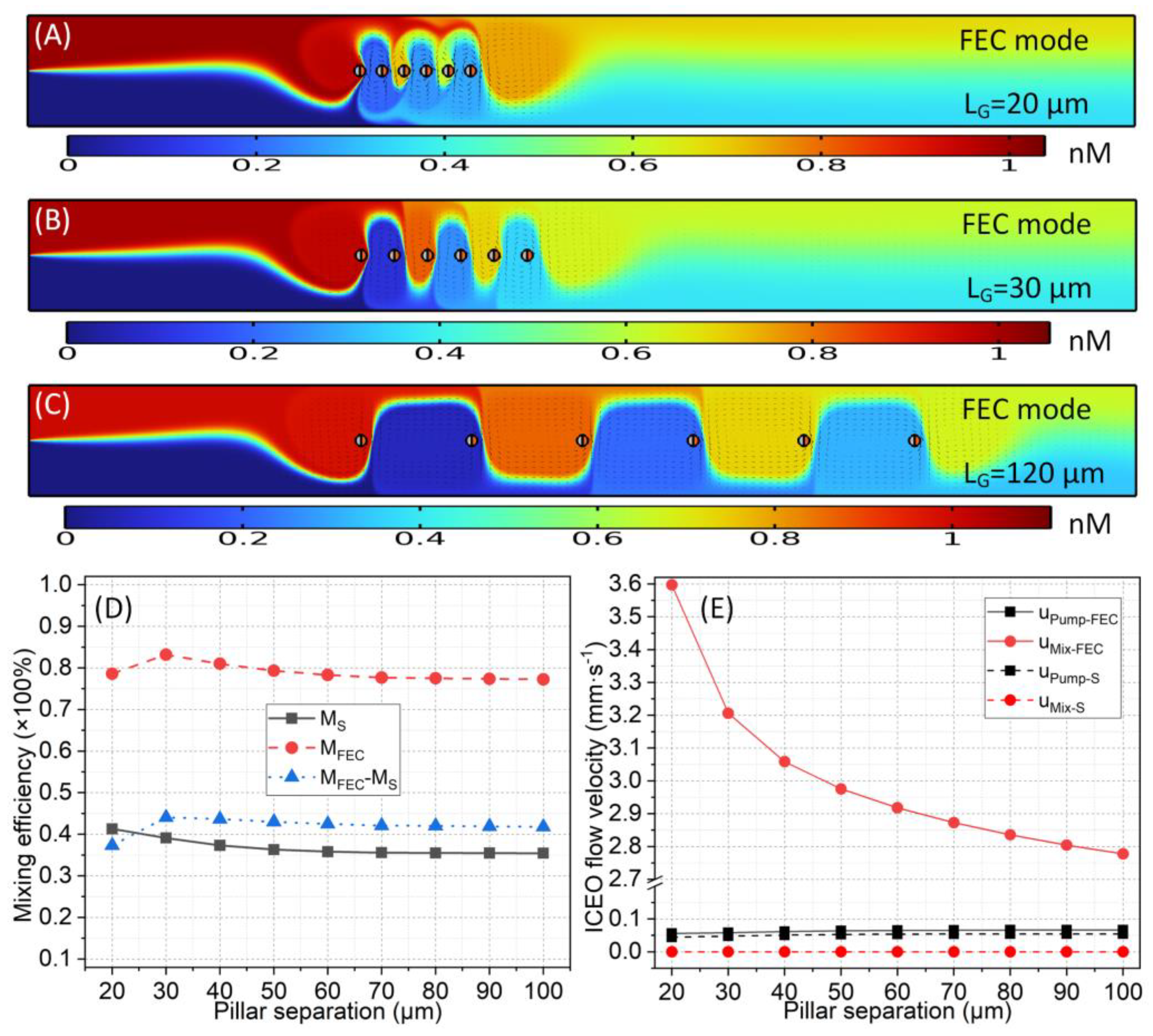
  • (b) Effect of inter-pillar separation
Based upon the optimal pillar radius of R = 5 μm, it is important for us to reveal the effect of the spatial separation between the neighboring pillars LG on the resulting device’s dual functionality. As shown in Figure 9A–C, an increase in the inter-post distance LG directly leads to an increase in the traveling wavelength of the diffusion-phase interface λ = 2LG.
With the rise in pillar separation LG from 20 to 100 μm, ux increases, but uy decreases monotonically. The LG has a positive (negative) effect on the horizontal pump motion ux (transversal rotating motion uy) (Figure 9E). Unlike the pillar size R governing the hydrodynamic interaction between the array unit and the channel sidewalls, the inter-pillar separation LG plays a more important role in adjusting the active interplay of the electrochemical polarization between the adjacent Janus pillars. A more closely packed discrete pillar array at a smaller LG tends to lower the pumping ability ux, but it enhances the transversal flow rotation uy for mixing (Figure 9E) due to the sophisticated charging dynamics of the interfacial capacitance skin for the practical discrete arrangement of Janus pillars with finite inter-unit separation. This abstruse action mechanism of the inter-pillar gap on the two orthogonal ICEO velocity components results in quite stable mixing performances under different LG from both the biased and the unbiased AC powering schemes (Figure 9D). Nevertheless, the preferable option is to use a special inter-pillar separation of LG = 30 μm to enable the maximum local improvement in the mixing performance of 44%, even without significantly sacrificing the horizontal pump-flow rate (Figure 9D).
  • (c) Effect of the number of discrete Janus pillars within the array
Regarding the geometry configuration, the number of Janus units in the discrete pillar array n also exerts an appreciable impact on the chip’s performance in active pumping and mixing, in addition to the R and the LG. With the optimal pillar radius of R = 5 μm and separation of LG = 30 μm, the mixing efficiency, two ICEO flow components, and their velocity ratio are quantified in terms of a direct comparison between biased and non-biased powering modes in Figure 10.
As the number of Janus posts n increases from n = 2 to n = 12, the pump-flow rate ux in both modes rises monotonically (Figure 10H). That is, placing more pillars within the device channel definitely has a positive effect on the ICEO’s driving force for forward sample delivery, which arises from the larger surface area of the ideally polarizable metal phase from which the ICEO slipping stems (Figure 10A–D)). In contrast, the transversal rotating perturbation uy is quite insensitive to changes in n because it grows by no more than 10% as the n increases by six-fold (Figure 10G). This intuitionally results in a more severe suppression of the velocity ratio χ = uy/ux at a larger n (Figure 10H). As expected, the mixing index MS for the non-biased mode decreases rapidly with n due to the enhanced pump-flow rate, leading to a reduction in the residence time of the particle species in the flow channel. Contrary to what would be expected from the variation trend of uy/ux, the biased powering mode in the bipolar Janus AC-FFET exhibits a relatively stable mixing effect within a broad range of n (Figure 10E). In fact, the effective actuating range of the transversal flow rotation uy is linearly proportional to the number of Janus pillars in the discrete array, leading to a substantial enhancement in the kinematic energy of uy with n (Figure 10A–D). However, this effect is not included in the approximate scaling analysis, so it is essential to obtain an accurate prediction of the device’s performance in active pumping and mixing by conducting simulations with our extended physical model of ICEO.
The authentic uy/ux may increase rather than decrease with n, which compensates for the decrease in the sample residence time from a larger ux to enable a stable distribution of the mixing index as a function of n under bipolar AC field-effect flow control. With the largest value of the number of discrete Janus pillars in the central array, n = 12, we can achieve a sufficiently strong pumping ability ux = 0.0815 mm·s−1, and an evident improvement in mixing effectiveness of △M = 50.5% at the same time (Figure 10E,F).

3.4.2. Effect of the Applied AC Voltage on the Integrated Device’s Performance

Once the device is fabricated with a fixed structure, it is not possible to change the channel geometry any further, and the regulation of the externally imposed AC voltage signal serves as a convenient way to achieve the flexible adjustment of the pumping and mixing performances based on a given kind of analyte dispersed in a standard working fluid. For this reason, it is intriguing to clarify how the dual functionality of the proposed microdevice responds to changes in the applied AC signal in terms of the field frequency, voltage amplitude, and gate-voltage-offset ratio β.
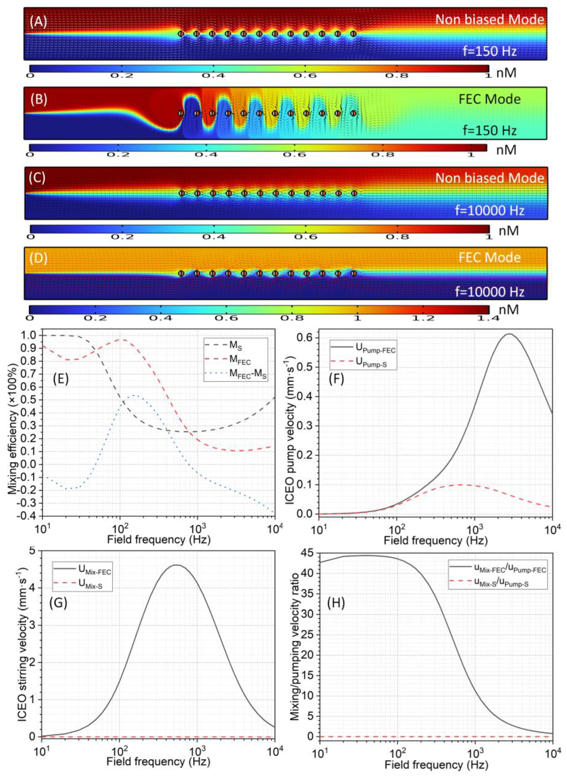
  • (a) Frequency dependence
As revealed by the basic fluid-mechanics study in Section 3.3, since the conducting DE plates and the metal phases of all the Janus pillars undergo non-negligible electrode polarization, which is potently affected by electrochemical ion relaxation in harmonic AC forcing, the frequency dependence of the two orthogonal ICEO flow-velocity components under AC field-effect control is quite complex, and the same is true for the mixing efficiency, as shown in Figure 11.
According to Figure 11F,G, both ux and uy exhibit a single relaxation peak at a middle frequency fideal. Because the fideal-ux for ux is larger than the fideal-uy for uy, the velocity ratio χ = uy/ux decreases from a stable low-frequency plateau to zero within the high-frequency limit (Figure 11H). This leads to a reduced mixing index at a higher frequency for the biased powering mode from an overall perspective (the red line in Figure 11E). Moreover, the unbiased mode performs the worst in terms of its mixing function in an intermediate frequency range (the black line in Figure 11E) on account of the shortest residence time tmix from an in situ peak ICEO pump motion (Figure 11F). From this subtle distinction, we can infer that the sample mixing is governed by lateral ICEO flow rotation uy and diffusive mass transfer in the biased and non-biased modes, respectively. Consequently, the mixing-index enhancement △M reaches a maximum of 53.8% at f = 150 Hz (Figure 11E).
As the applied field frequency moves away from the critical point of 150 Hz, the △M decays dramatically. Importantly, the originally positive △M turns into a negative value for f < 50 Hz and f > 800 Hz (Figure 11E), which indicates that the mixing efficiency in the biased mode is even lower than that in the conventional unbiased mode (Figure 11A–D), which is mainly due to the augmented pump-flow rate along the channel length (Figure 11F). Thus, when the applied frequency is inappropriate, the advanced technique of bipolar Janus AC-FFET fails, in turn, to improve the device’s mixing performance, even if the pumping ability can be enhanced. Therefore, the ideal working frequency of the given device architecture is f = 150 Hz, at which we can acquire the optimum enhancement in mixing performance, together with a moderate ICEO pump-flow rate.
  • (b) Effect of the amplitude of AC-driven voltage
According to Equations (25) and (26), both the horizontal pump motion ux and the transversal rotating perturbation uy are linearly proportional to the squared AC-driven-voltage amplitude, implying that it may be possible to regulate the pumping and mixing behavior by simply raising the voltage magnitude applied to the two DE plates embedded in the channel sidewalls. As shown in Figure 12F,G, the simulation results indicate that both ux and uy grow quadratically with the AC-driven voltage VD under the prescribed gate-voltage-offset ratio βodd = −βeven = 0.8, in good agreement with the preliminary dimensional analysis. As a result, their ratio χ = uy/ux almost remains the same as a function of VD (Figure 12H). In this situation, diffusive mass transfer governs the trend of the variation in the mixing behavior in both biased and unbiased modes, which decreases as the AC-driven voltage increases due to the enhanced pump-flow rate causing a lower in-channel sample-residence time.
On the one hand, under an extremely small driving voltage, since the pump motion ux is excessively weak, the mixing index for the unbiased mode is already very good and close to 100%, leading to a finite enhancement in mixing performance of VD ≤ 1 V (Figure 12A,B,E). On the other hand, under a relatively large driving voltage with VD ≥ 2 V, since the difference in ux between the unbiased and biased modes is amplified to a great extent, the molecular-diffusion effect of the biased mode decays faster with VD (Figure 12F), which further inhibits the improvement in mixing behavior (Figure 12C–E). Accordingly, an optimal driving voltage of VD = 2 V enhances the mixing index by a maximum of 53.2% compared to the traditional unbiased mode by exploiting the bipolar Janus AC-FFET.
  • (c) Effect of gate-voltage offset
For realistic applications, it is indispensable to know how the magnitude of gate-voltage bias affects field-effect-adjustable ICEO pumping and mixing at a given AC-driven-voltage signal. With the optimal signal frequency f = 150 Hz and driving voltage VD = 2 V in the current device design, we examine the importance of bipolar AC field-effect flow control in generating controllable flow behaviors along the length and width of the channel.
With the definition of absolute voltage bias △VG = VG − 0.5VD, a dimensionless number β = (VG − 0.5VD)/0.5VD is extractable, and its specific value is bounded between −1 and 1 in an actual situation, in which 0 ≤ VG ≤ VD. When the bias ratio β of the gate voltage imposed on the metal phase of the Janus pillar becomes zero, although an electrokinetic flow component is induced along the channel axis due to non-uniform interfacial polarizability, all the units in the post array float in external AC fields with VG = 0.5VD, and no symmetry breaking in the transversal ICEO-vortex flow pattern takes place, resulting in only active ICEO pumping without apparent sample stirring (Figure 11A).
As the absolute value of β increases gradually from 0 to 0.9, the gate voltage varies from VD/2 to the peak magnitude with VG-odd = 0.95VD and VG-even = 0.05VD, the swirling ICEO fluid motion even becomes asymmetric in the transversal direction, and it tends to behave as one large whirlpool around each pillar (Figure 13A–D)). At a larger gate-offset ratio, the biased ICEO eddies rotate in one specific direction along the width of the channel, which is upward and downward for the odd- and even-numbered pillars, respectively. For the current integrated device design with the bipolarly biased gate-voltage sequence of βodd = −βeven, asymmetric ICEO eddies whose rotating direction is constantly reversed between adjacent microcylinders are induced along the discrete Janus pillar via AC field-effect flow control, which is, therefore, more apt for analyte mixing. As the gate-voltage offset ratio β increases from 0.1 to 0.9, although the traveling wavelength of the diffusion-phase interface remains unchanged, the amplitude of lateral displacement enhances significantly (Figure 13A–D)), implying an improved mixing performance (see the Supplementary Movie).
Due to an enhancement in the input electric energy, the horizontal pump motion ux originating in the ICEO rises as the gate-voltage bias increases (Figure 13F). Moreover, the transversal rotating perturbation uy responsible for the sample stirring is linearly proportional to β and vanishes when the gate offset is zero, with β = 0 (Figure 13G). Thus, in AC field-effect flow control, it is preferable to selectively control uy rather than ux, resulting in a dramatic increase in χ = uy/ux with the gate-voltage-offset ratio (Figure 13H). In this way, for the biased modes, lateral ICEO rotating convection dominates the dynamics of the mixing between the stratified liquid streams (Figure 13A–D)). As the gate-voltage offset increases, the mixing index grows rapidly and tends to attain a stable plateau value when β exceeds 0.5 (Figure 13E). Not only is the mixing performance improved (Figure 13E), but the axial pump’s motion is also intensified to a certain extent (Figure 13F). Thus, the enhanced pump ability does not, in turn, have a direct negative effect on the device’s mixing efficiency.
Based upon the analysis above, a flexible adjustment of the gate-voltage offset imposed on the metal phase of each Janus micropillar enables the simultaneous improvement in sample throughput and mixing performance of the integrated microdevice, which serves as the most important physical essence of Janus AC-FFET. By contrast, all the other parameters, such as the discrete pillar arrangement, the AC-driven voltage, and the field frequency, usually have opposite effects on the device’s dual functionality, and a compromise must be found between them to obtain reasonable mixing-index enhancement under a sufficient pump-flow rate. Accordingly, we should first consider the combination of gate-voltage polarities that should be applied to achieve the desired multiple functions of the microfluidic device, after which other geometry and voltage parameters can be specifically optimized.

4. Conclusions

In summary, we provided new physical perspectives through both a scaling analysis and a numerical investigation to introduce the novel concept of AC field-effect control of ICEO streaming next to metal–dielectric Janus micropillars, namely, the unique configuration of the AC flow-field-effect transistor using Janus cylinders (Janus AC-FFET). This new operational tool for stratified sample streams in microfluidics arises from the time-averaged Coulomb force exerted by external AC-driven electric fields on the gate-voltage-induced diffuse screening cloud on the unevenly polarizable surface of a Janus post, the metal phase of which is subjected to an arbitrary gate-voltage supply. Our mathematical analysis clarifies for the first time that AC field-effect-mediated ICEO can produce horizontal pump ux and transversal mixing-flow components uy that are orthogonal to each other simultaneously in microfluidic channels. This kind of field-effect-reconfigurable AC electroconvection driven by nonlinear electro-osmosis is conceivably related to several challenging on-chip applications requiring liquid-phase actuation in multiple directions, such as the concurrent active pumping and mixing of sample analytes, the 3D-profile scanning and dielectric characterization of biological cells, and localized particle stacking in microfabricated fluid networks.
The axial propelling component ux, due to the left–right ICEO flow symmetry breaking from the inhomogeneous polarizability of the Janus pillar, and the transversal rotating component uy, due to the up–down symmetry breaking in the electrokinetic vortex flow pattern from the biased AC powering scheme, are responsible for the pumping and mixing of the microflows, respectively. When applying an adjustable gate-voltage offset to the metal phase of the Janus entity, AC field-effect flow control tends to selectively control the mechanical behavior of uy rather than ux, and the magnitude of uy can be separately controlled by varying the gate bias while not exerting an evident influence on ux. Moreover, automatic conversion in the rotating direction of uy is conveniently realizable by simply reversing the gate voltage polarity.
Inspired by this, we further proposed an advanced microfluidic pump and mixer driven by the bipolar Janus AC-FFET, in which each pair of neighboring pillars is sequentially subjected to two oppositely polarized gate voltages along an array of discrete Janus micropillars integrated into the middle of the device channel. When inducing active zigzag streamlines, these asymmetric ICEO whirlpools with constantly changing swirling directions between adjacent array elements greatly facilitate on-demand sample mixing via the improved Janus AC-FFET using bipolar gate terminals. Unlike all the other geometric and voltage parameters, which always require an elaborate trade-off kin the device’s dual functionality, AC field-effect flow control allows the simultaneous enhancement of the pump ability and mixing efficiency of the integrated device’s design, which is therefore defined as the core physical content of AC field-effect-mediated ICEO fluid motion using metal–dielectric Janus micropillars.
Many more investigations still need to be conducted in the future. For instance, although the present physical model can describe the phenomenon of ICEO streaming around solid objects with arbitrary electrical polarizability, it is only valid under the Debye–Hückel limit, and reasonable extensions—which include a theoretical study on large double-layer voltage-drop effects—are necessary. Under these conditions, the linear asymptotic analysis for sinusoidal AC actuation used herein may malfunction, and newly developed physical descriptions must consider the various nonlinear dynamics in electrochemical transport systems when the Dukhin number is not negligibly small. It is firmly believed that the AC field-effect-reconfigurable ICEO-vortex flow pattern with inhomogeneous Janus pillars will trigger dramatic advances in the interdisciplinary research fields of micro/nano-fluidics, soft matter, and analytical chemistry, and create precious opportunities for positive communications between chemical engineers, hydrodynamic experts, and applied mathematicians in the near future.

Supplementary Materials

The following supporting information can be downloaded at: https://www.mdpi.com/article/10.3390/app13148253/s1. Movie S1: Simultaneous active pumping and mixing of stratified liquid contents driven by Janus AC-FFET in microfluidics; Supplementary Information.

Author Contributions

W.L. and Y.L. proposed the idea. W.L., J.C. and Z.G. designed the research. W.L., Y.T. and Y.C. derived the theory and conducted the simulation. W.L. and Y.C. drew and created the figures. W.L., Y.T. and J.C. wrote the paper. All authors have read and agreed to the published version of the manuscript.

Funding

We sincerely acknowledge the financial support from the National Natural Science Foundation of China (no. 12172064, no. 12072096), the Key Research and Development Program of Shaanxi Province (no. 2022GY-208, NO. 2021KW-13), the Fundamental Research Funds for the Central Universities CHD (no. 300102322201), and the Self-Planned Task (grant no. SKLRS201803B) of the State Key Laboratory of Robotics and System (HIT).

Institutional Review Board Statement

Not applicable.

Informed Consent Statement

Not applicable.

Data Availability Statement

The data that support the findings of this study are available from the corresponding author upon reasonable request.

Conflicts of Interest

The authors declare no conflict of interest.

Abbreviations

ACET, alternating-current electrothermal; AC-FFET, alternating-current flow-field-effect transistor; DE, driving electrode; DEP, dielectrophoretic; EK, electrokinetic; EO, electro-osmosis; EHD, electrohydrodynamic; IDL, induced double layer; IZP, induced zeta potential; ICEK, induced-charge electrokinetic; ICEO, induced-charge electro-osmotic; LEA, local electroneutrality assumption.

References

  1. Dittrich, P.S.; Tachikawa, K.; Manz, A. Micro total analysis systems. Latest advancements and trends. Anal. Chem. 2006, 78, 3887–3908. [Google Scholar]
  2. Squires, T.M.; Quake, S.R. Microfluidics: Fluid physics at the nanoliter scale. Rev. Mod. Phys. 2005, 77, 977. [Google Scholar]
  3. Zhao, C.X.; Miller, E.; Cooper-White, J.J.; Middelberg, A.P. Effects of fluid–fluid interfacial elasticity on droplet formation in microfluidic devices. AIChE J. 2011, 57, 1669–1677. [Google Scholar] [CrossRef]
  4. Lee, C.Y.; Chang, C.L.; Wang, Y.N.; Fu, L.M. Microfluidic Mixing: A Review. Int. J. Mol. Sci. 2011, 12, 3263. [Google Scholar] [CrossRef] [Green Version]
  5. Green, J.; Holdø, A.; Khan, A. A review of passive and active mixing systems in microfluidic devices. Int. J. Multiphys. 2009, 1, 1–32. [Google Scholar] [CrossRef]
  6. Chen, L.; Wang, G.; Lim, C.; Seong, G.H.; Choo, J.; Lee, E.K.; Kang, S.H.; Song, J.M. Evaluation of passive mixing behaviors in a pillar obstruction poly(dimethylsiloxane) microfluidic mixer using fluorescence microscopy. Microfluid. Nanofluidics 2009, 7, 267–273. [Google Scholar] [CrossRef]
  7. Sritharan, K.; Strobl, C.; Schneider, M.; Wixforth, A.; Guttenberg, Z.V. Acoustic mixing at low Reynold’s numbers. Appl. Phys. Lett. 2006, 88, 054102. [Google Scholar] [CrossRef]
  8. Rida, A.; Gijs, M.A. Manipulation of self-assembled structures of magnetic beads for microfluidic mixing and assaying. Anal. Chem. 2004, 76, 6239–6246. [Google Scholar] [CrossRef] [PubMed]
  9. Rashidi, S.; Bafekr, H.; Valipour, M.S.; Esfahani, J.A. A review on the application, simulation, and experiment of the electrokinetic mixers. Chem. Eng. Process.-Process Intensif. 2018, 126, 108–122. [Google Scholar] [CrossRef]
  10. Velev, O.D.; Bhatt, K.H. On-chip micromanipulation and assembly of colloidal particles by electric fields. Soft Matter 2006, 2, 738–750. [Google Scholar] [CrossRef]
  11. Velev, O.D.; Gangwal, S.; Petsev, D.N. Particle-localized AC and DC manipulation and electrokinetics. Annu. Rep. Sect. C Phys. Chem. 2009, 105, 213–246. [Google Scholar] [CrossRef]
  12. Ory, S.; Ehud, Y. The Taylor-Melcher leaky dielectric model as a macroscale electrokinetic description. J. Fluid Mech. 2015, 773, 1–33. [Google Scholar]
  13. Hu, G.; Li, D. Multiscale phenomena in microfluidics and nanofluidics. Chem. Eng. Sci. 2007, 62, 3443–3454. [Google Scholar] [CrossRef]
  14. Zhao, C.X.; Chen, D.; Hui, Y.; Weitz, D.A.; Middelberg, A.P. Controlled Generation of Ultrathin-Shell Double Emulsions and Studies on Their Stability. ChemPhysChem 2017, 18, 1393–1399. [Google Scholar] [CrossRef] [PubMed] [Green Version]
  15. Saghatchi, R.; Rahmat, A.; Yildiz, M. Electrohydrodynamics of a droplet in a highly confined domain: A numerical study. Phys. Fluids 2020, 32, 123305. [Google Scholar] [CrossRef]
  16. Santra, S.; Sen, D.; Das, S.; Chakraborty, S. Electrohydrodynamic interaction between droplet pairs in a confined shear flow. Phys. Fluids 2019, 31, 032005. [Google Scholar] [CrossRef] [Green Version]
  17. Kunti, G.; Mondal, P.K.; Bhattacharya, A.; Chakraborty, S. Electrothermally modulated contact line dynamics of a binary fluid in a patterned fluidic environment. Phys. Fluids 2018, 30, 092005. [Google Scholar] [CrossRef]
  18. Kunti, G.; Bhattacharya, A.; Chakraborty, S. Alternating current electrothermal modulated moving contact line dynamics of immiscible binary fluids over patterned surfaces. Soft Matter 2017, 13, 6377–6389. [Google Scholar] [CrossRef]
  19. Liu, W.; Tao, Y.; Li, Y.; Ge, Z.; Wu, Q.; Ren, Y. Numerical characterization of transient electrohydrodynamic deformation and coalescence of single-core double emulsion droplets by AC field dielectrophoresis. Chem. Eng. Sci. 2023, 277, 118877. [Google Scholar] [CrossRef]
  20. Liu, W.; Ren, Y.; Tao, Y.; Chen, X.; Yao, B.; Hui, M.; Bai, L. Control of two-phase flow in microfluidics using out-of-phase electroconvective streaming. Phys. Fluids 2017, 29, 112002. [Google Scholar] [CrossRef]
  21. Bazant, M.Z.; Squires, T.M. Induced-charge electrokinetic phenomena: Theory and microfluidic applications. Phys. Rev. Lett. 2004, 92, 066101. [Google Scholar] [CrossRef] [Green Version]
  22. López-Vizcaíno, R.; Navarro, V.; Yustres, Á. Two-Dimensional Modelling Approach for Electrokinetic Water Transport in Unsaturated Kaolinite. Appl. Sci. 2022, 13, 519. [Google Scholar] [CrossRef]
  23. Qi, W.; Shen, Y.; Li, S.; Chen, K. Study on the Interaction between the Reduction and Remediation of Dredged Sediments from Tai Lake Based on Vacuum Electro-Osmosis. Appl. Sci. 2023, 13, 741. [Google Scholar] [CrossRef]
  24. Noreen, S.; Waheed, S.; Hussanan, A.; Lu, D. Analytical solution for heat transfer in electroosmotic flow of a carreau fluid in a wavy microchannel. Appl. Sci. 2019, 9, 4359. [Google Scholar] [CrossRef] [Green Version]
  25. Waheed, S.; Noreen, S.; Hussanan, A. Study of heat and mass transfer in electroosmotic flow of third order fluid through peristaltic microchannels. Appl. Sci. 2019, 9, 2164. [Google Scholar] [CrossRef] [Green Version]
  26. Tao, Y.; Liu, W.; Ge, Z.; Yao, B.; Ren, Y. Alternating-current nonlinear electrokinetics in microfluidic insulator-decorated bipolar electrochemistry. Phys. Fluids 2022, 34, 112002. [Google Scholar] [CrossRef]
  27. Tripathi, D.; Narla, V.K.; Aboelkassem, Y. Electrokinetic membrane pumping flow model in a microchannel. Phys. Fluids 2020, 32, 082004. [Google Scholar] [CrossRef]
  28. Chen, L.; Lee, S.; Choo, J.; Lee, E.K. Continuous dynamic flow micropumps for microfluid manipulation. J. Micromech. Microeng. 2007, 18, 013001. [Google Scholar] [CrossRef]
  29. Chen, L.; Ma, J.; Guan, Y. Study of an electroosmotic pump for liquid delivery and its application in capillary column liquid chromatography. J. Chromatogr. A 2004, 1028, 219–226. [Google Scholar] [CrossRef]
  30. Salari, A.; Navi, M.; Dalton, C. A novel alternating current multiple array electrothermal micropump for lab-on-a-chip applications. Biomicrofluidics 2015, 9, 014113. [Google Scholar] [CrossRef] [Green Version]
  31. Park, S.; Koklu, M.; BeskoK, A. Particle trapping in high-conductivity media with electrothermally enhanced negative dielectrophoresis. Anal. Chem. 2009, 81, 2303–2310. [Google Scholar] [CrossRef]
  32. González, A.; Ramos, A.; Morgan, H.; Green, N.G.; Castellanos, A. Electrothermal flows generated by alternating and rotating electric fields in microsystems. J. Fluid Mech. 2006, 564, 415–433. [Google Scholar] [CrossRef] [Green Version]
  33. Prabhakaran, R.A.; Zhou, Y.; Zhao, C.; Hu, G.; Song, Y.; Wang, J.; Yang, C.; Xuan, X. Induced charge effects on electrokinetic entry flow. Phys. Fluids 2017, 29, 42–48. [Google Scholar] [CrossRef]
  34. Gregersen, M.M.; Andersen, M.B.; Soni, G.; Meinhart, C.; Bruus, H. Numerical analysis of finite Debye-length effects in induced-charge electro-osmosis. Phys. Rev. E 2009, 79, 066316. [Google Scholar] [CrossRef] [PubMed] [Green Version]
  35. Yossifon, G.; Frankel, I.; Miloh, T. Symmetry breaking in induced-charge electro-osmosis over polarizable spheroids. Phys. Fluids 2007, 19, 217. [Google Scholar] [CrossRef]
  36. Studer, V.; Pépin, A.; Chen, Y.; Ajdari, A. An integrated AC electrokinetic pump in a microfluidic loop for fast and tunable flow control. Analyst 2004, 129, 944–949. [Google Scholar] [CrossRef] [PubMed]
  37. Van Der Wouden, E.; Hermes, D.; Gardeniers, J.; Van Den Berg, A. Directional flow induced by synchronized longitudinal and zeta-potential controlling AC-electrical fields. Lab A Chip 2006, 6, 1300–1305. [Google Scholar] [CrossRef]
  38. Kale, A.; Song, L.; Lu, X.; Yu, L.; Hu, G.; Xuan, X. Electrothermal enrichment of submicron particles in an insulator-based dielectrophoretic microdevice. Electrophoresis 2017, 39, 887–896. [Google Scholar] [CrossRef] [PubMed] [Green Version]
  39. Du, E.; Manoochehri, S. Enhanced ac electrothermal fluidic pumping in microgrooved channels. J. Appl. Phys. 2008, 104, 064902. [Google Scholar] [CrossRef] [Green Version]
  40. Stubbe, M.; Holtappels, M.; Gimsa, J. A new working principle for ac electro-hydrodynamic on-chip micro-pumps. J. Phys. D Appl. Phys. 2007, 40, 6850. [Google Scholar] [CrossRef]
  41. Sasaki, N.; Kitamori, T.; Kim, H.B. Fluid mixing using AC electrothermal flow on meandering electrodes in a microchannel. Electrophoresis 2012, 33, 2668–2673. [Google Scholar] [CrossRef] [PubMed]
  42. Feng, J.; Krishnamoorthy, S.; Sundaram, S. Numerical analysis of mixing by electrothermal induced flow in microfluidic systems. Biomicrofluidics 2007, 1, 024102. [Google Scholar] [CrossRef] [PubMed] [Green Version]
  43. Stubbe, M.; Gimsa, J. A short review on AC electro-thermal micropumps based on smeared structural polarizations in the presence of a temperature gradient. Colloids Surf. A Physicochem. Eng. Asp. 2011, 376, 97–101. [Google Scholar] [CrossRef]
  44. Velasco, V.; Williams, S.J. Electrokinetic concentration, patterning, and sorting of colloids with thin film heaters. J. Colloid Interface Sci. 2013, 394, 598–603. [Google Scholar] [CrossRef]
  45. Yang, K.; Wu, J. Numerical study of in situ preconcentration for rapid and sensitive nanoparticle detection. Biomicrofluidics 2010, 4, 034106. [Google Scholar] [CrossRef] [PubMed] [Green Version]
  46. Felten, M.; Staroske, W.; Jaeger, M.S.; Schwille, P.; Duschl, C. Accumulation and filtering of nanoparticles in microchannels using electrohydrodynamically induced vortical flows. Electrophoresis 2008, 29, 2987–2996. [Google Scholar] [CrossRef] [PubMed]
  47. Feldman, H.C.; Sigurdson, M.; Meinhart, C.D. AC electrothermal enhancement of heterogeneous assays in microfluidics. Lab A Chip 2007, 7, 1553–1559. [Google Scholar] [CrossRef]
  48. Squires, T.M. Induced-charge electrokinetics: Fundamental challenges and opportunities. Lab A Chip 2009, 9, 2477–2483. [Google Scholar] [CrossRef]
  49. Pascall, A.J.; Squires, T.M. Induced charge electro-osmosis over controllably contaminated electrodes. Phys. Rev. Lett. 2010, 104, 088301. [Google Scholar] [CrossRef]
  50. Peng, C.; Lazo, I.; Shiyanovskii, S.V.; Lavrentovich, O.D. Induced-charge electro-osmosis around metal and Janus spheres in water: Patterns of flow and breaking symmetries. Phys. Rev. E 2014, 90, 051002. [Google Scholar] [CrossRef] [Green Version]
  51. Paustian, J.S.; Pascall, A.J.; Wilson, N.M.; Squires, T.M. Induced charge electroosmosis micropumps using arrays of Janus micropillars. Lab A Chip 2014, 14, 3300–3312. [Google Scholar] [CrossRef] [Green Version]
  52. Chang, S.T.; Paunov, V.N.; Petsev, D.N.; Velev, O.D. Remotely powered self-propelling particles and micropumps based on miniature diodes. Nat. Mater. 2007, 6, 235–240. [Google Scholar] [CrossRef]
  53. Chang, S.T.; Beaumont, E.; Petsev, D.N.; Velev, O.D. Remotely powered distributed microfluidic pumps and mixers based on miniature diodes. Lab A Chip 2008, 8, 117–124. [Google Scholar] [CrossRef]
  54. Zehavi, M.; Sofer, D.; Miloh, T.; Velev, O.D.; Yossifon, G. Optically Modulated Propulsion of Electric-Field-Powered Photoconducting Janus Particles. Phys. Rev. Appl. 2022, 18, 024060. [Google Scholar] [CrossRef]
  55. Bhatt, K.H.; Grego, S.; Velev, O.D. An AC electrokinetic technique for collection and concentration of particles and cells on patterned electrodes. Langmuir 2005, 21, 6603–6612. [Google Scholar] [CrossRef] [PubMed]
  56. Shields, C.W., IV; Han, K.; Ma, F.; Miloh, T.; Yossifon, G.; Velev, O.D. Supercolloidal spinners: Complex active particles for electrically powered and switchable rotation. Adv. Funct. Mater. 2018, 28, 1803465. [Google Scholar] [CrossRef]
  57. Diwakar, N.M.; Kunti, G.; Miloh, T.; Yossifon, G.; Velev, O.D.J.A.F.M. AC electrohydrodynamic propulsion and rotation of active particles of engineered shape and asymmetry. Curr. Opin. Colloid Interface Sci. 2022, 59, 101586. [Google Scholar]
  58. Gangwal, S.; Cayre, O.J.; Bazant, M.Z.; Velev, O.D. Induced-charge electrophoresis of metallodielectric particles. Phys. Rev. Lett. 2008, 100, 058302. [Google Scholar] [CrossRef] [Green Version]
  59. Gangwal, S.; Pawar, A.; Kretzschmar, I.; Velev, O.D. Programmed assembly of metallodielectric patchy particles in external AC electric fields. Soft Matter 2010, 6, 1413–1418. [Google Scholar] [CrossRef]
  60. Sharma, R.; Velev, O.D. Remote steering of self-propelling microcircuits by modulated electric field. Adv. Funct. Mater. 2015, 25, 5512–5519. [Google Scholar] [CrossRef]
  61. Hermanson, K.D.; Lumsdon, S.O.; Williams, J.P.; Kaler, E.W.; Velev, O.D. Dielectrophoretic assembly of electrically functional microwires from nanoparticle suspensions. Science 2001, 294, 1082–1086. [Google Scholar] [CrossRef]
  62. Squires, T.M.; Bazant, M.Z. Induced-charge electro-osmosis. J. Fluid Mech. 2004, 509, 217–252. [Google Scholar] [CrossRef] [Green Version]
  63. Schnitzer, O.; Yariv, E. Induced-charge electro-osmosis beyond weak fields. Phys. Rev. E 2012, 86, 061506. [Google Scholar] [CrossRef] [PubMed]
  64. Yossifon, G.; Frankel, I.; Miloh, T. On electro-osmotic flows through microchannel junctions. Phys. Fluids 2006, 18, 381. [Google Scholar] [CrossRef]
  65. Ren, Y.; Liu, W.; Tao, Y.; Hui, M.; Wu, Q. On ac-field-induced nonlinear electroosmosis next to the sharp corner-field-singularity of leaky dielectric blocks and its application in on-chip micro-mixing. Micromachines 2018, 9, 102. [Google Scholar] [CrossRef] [PubMed] [Green Version]
  66. Schasfoort, R.B.; Schlautmann, S.; Hendrikse, J.; van den Berg, A. Field-effect flow control for microfabricated fluidic networks. Science 1999, 286, 942–945. [Google Scholar] [CrossRef] [PubMed] [Green Version]
  67. Van Der Wouden, E.; Heuser, T.; Hermes, D.; Oosterbroek, R.; Gardeniers, J.; Van Den Berg, A. Field-effect control of electro-osmotic flow in microfluidic networks. Colloids Surf. A Physicochem. Eng. Asp. 2005, 267, 110–116. [Google Scholar] [CrossRef] [Green Version]
  68. Guan, W.; Fan, R.; Reed, M.A. Field-effect reconfigurable nanofluidic ionic diodes. Nat. Commun. 2011, 2, 506. [Google Scholar] [CrossRef] [PubMed] [Green Version]
Figure 1. A schematic diagram of a microfluidic device using AC field-effect control on ICEO flow profiles consisting of both horizontal pump motion ux and transversal rotating motion uy around metal–dielectric Janus micropillars, which can actively deal with stratified liquid contents along the two orthogonal flow directions via pure nonlinear electro-osmosis. (A) The geometric configuration of the advanced 3D device design of an active microfluidic pump and mixer with dual functionality employing bipolar Janus AC-FFET, in which an array of discrete Janus pillars is arranged along the bottom surface of a straight microchannel embedding a pair of conducting DE plates on both sidewalls. The odd- and even-numbered Janus units in the array are each subjected to two oppositely polarized gate terminals, resulting in zigzag electrokinetic streamlines, which can effectively pump, rotate, and stretch the two-phase contact interface at the same time, even without an external moving part. (B) A 2D illustration of the geometric size of the discrete pillar arrangement and device channel, as well as the definition of Cartesian and polar coordinate systems. (CE) A 2D schematic representation of the physical mechanism of AC field-effect-adjustable electrochemical polarization and ICEO streaming adjacent to a single metal–dielectric Janus microcylinder immersed in electrolyte solution, under the influence of a background electric field applied across the channel width. (C) When the target post is free from external wiring, i.e., VG = 0.5VD, two symmetric ICEO eddies appear selectively on its downstream conducting surface, leading to a forward ICEO pump motion along the horizontal direction, mainly due to the inherent uneven electrical polarizability of the Janus micropillar itself, with no net transversal rotating motion. (D,E) Once its metal phase is exposed to a positively (negatively) biased gate terminal, i.e., VG > 0.5VD (VG < 0.5VD), more anions (cations) than cations (anions) accumulate at the ideally polarizable metal surface, so the clockwise (anticlockwise) rotating vortex on the bottom (top) side becomes larger and dominates the anticlockwise (clockwise) counterpart on the top (bottom) side. This additional symmetry breaking in the transversal electrokinetic vortex flow pattern gives rise to a net rotating fluid motion uy for sample mixing in the upward (downward) direction, respectively, and the original function of automatic fluid pumping in the forward direction ux is maintained concurrently from an unchanged polarizability gradient. In this way, Janus AC-FFET proposed herein greatly facilitates simultaneous active pumping and mixing of stratified analyte streams with a simple device geometry. (F) A sketch of the 2D computation domain used in current numerical simulation.
Applsci 13 08253 g001
Figure 2. A simulation validation of our proposed physical model against the standard benchmark, in which a uniform metal cylinder immersed in aqueous electrolyte solution is fixed in space in the presence of a uniform background AC electric field applied in the transversal direction. (A) Numerical prediction of the familiar quadrupolar ICEO-vortex flow field adjacent to an ideally polarizable conducting cylinder in terms of a surface and streamline plot of nonlinear electro-osmotic streaming. (BD) A quantitative comparison between the analytical and numerical solutions of various field variables evaluated at the metal/electrolyte interface; (B) position-dependent tangential ICEO slipping velocity uθ as a function of the polar angle under four distinct field frequencies at VD = 2 V; (C) frequency-dependent surface-averaged abs(uθ) at VD = 2 V; and (D) driving-voltage-dependent surface-averaged abs(uθ) at f = 200 Hz.
Applsci 13 08253 g002
Figure 3. A simulation analysis of the influence of the metal-phase angle α of the Janus micropillar on symmetry breaking in the horizontal ICEO flow profile, which effectively gives rise to a net forward-pump-flow component responsible for unidirectional sample delivery towards channel exit, for given values of f = 200 Hz, VD = 2 V, and R = 5 μm, in the conventional unbiased AC powering mode. (AD) A surface and streamline plot of the circulating ICEO flow field next to an individual metal–dielectric Janus cylinder of varying metal-phase angles α: (A) α = 0°, (B) α = 90°, (C) α = 180°, and (D) α = 270°. (E) Position-dependent tangential ICEO slipping uθ on the dielectric surface of Janus post as a function of the polar angle for α = 0°. (F) A quantitative comparison of position-dependent tangential ICEO slipping uθ on the polarizable surface of Janus post as a function of the polar angle under α = 90°, 180°, 270°, and 360°. (G) A vivid comparison of the net axial pump velocity ux and transversal mixing velocity uy as a function of the metal-phase angle. It is noteworthy that the metal-phase angle α can be equivalently represented by the volumetric fraction of the metal phase Vfm in the inhomogeneous Janus pillar. Most importantly, the peak pump performance occurred when using a symmetric Janus post with equal dielectric and metal phases, as commonly seen in real experiments.
Applsci 13 08253 g003
Figure 4. Simulation results of the influence of the electric-field frequency on forward pumping of electrolyte via horizontal symmetry breaking in ICEO flow behavior for different radii of the Janus post under a given driving voltage VD = 2 V (when the metal phase of the Janus pillar is free from external wiring). (AD) A surface and streamline plot of the circulating ICEO flow field around a single Janus pillar of different radii at their respective ideal pumping frequencies: (A) R = 2.5 μm at fideal = 1000 Hz, (B) R = 5 μm at fideal = 700 Hz, (C) R = 7.5 μm at fideal = 600 Hz, and (D) R = 10 μm at fideal = 500 Hz. (E) Frequency-dependent pump-flow rate under varying post radii. (F) Ideal pumping frequency and peak pump velocity as a function of the radius of Janus pillar. (G) A quantitative comparison of the magnitude of tangential ICEO slipping velocity as a function of field frequency for R = 5 μm. (H) Position-dependent ICEO slip velocity on the polarizable pillar surface as a function of the polar angle for different radii of the Janus entity.
Applsci 13 08253 g004
Figure 5. A simulation analysis of the effect of AC gate-voltage offset on the resulting pump ux and mixing-flow behavior uy orthogonal to each other driven by Janus AC-FFET, in which the metal phase of a Janus micropillar is no longer free from external Ohm contact and is instead subjected to arbitrary AC field-effect flow control, for given values of VD = 2 V, f = 200 Hz, and R = 5 μm. (AD) A surface and streamline plot of ICEO-vortex flow field with both horizontal and transversal symmetric breaking when the Janus pillar is subjected to distinct AC gate voltage supply: (A) an apparently negatively-polarized gating-metal phase with VG = 0.05 VD and β = −0.9; (B) a slightly negatively polarized gating-metal phase with VG = 0.45 VD and β = −0.1; (C) a slightly positively polarized gating-metal phase with VG = 0.55 VD and β = 0.1; and (D) an apparently positively polarized gating-metal phase with VG = 0.95 VD and β = 0.9. (E) The horizontal pump velocity ux, transversal mixing velocity uy, and velocity-component ratio uy/ux as a function of the gate-voltage-offset ratio β. (F) A quantitative comparison of the magnitude of tangential ICEO slipping and induced zeta potential between the dielectric- and metal-phase surfaces of the Janus micropillar. (G) Position-dependent tangential ICEO velocity on the polarizable post surface as a function of the polar angle under varying β. (H) Position-dependent induced zeta potential on the polarizable pillar surface as a function of the polar angle under varying β.
Applsci 13 08253 g005
Figure 6. The calculation results of the AC field-frequency effect on the resulting pump ux and mixing-flow behavior uy orthogonal to each other due to Janus AC-FFET, in which the metal phase of a Janus micropillar of varying radii is exposed to an arbitrary gate voltage amplitude VG = 0.9VD = 1.8 V for a given driving voltage VD = 2 V. (A) Frequency-dependent ICEO pump speed along channel length for different pillar radii. (B) Frequency-dependent ICEO mixing velocity along channel width for distinct pillar radii. (C) Frequency-dependent mixing/pumping-velocity-component ratio uy/ux under varying pillar radii. (D) A quantitative comparison of tangential ICEO slipping and induced zeta potential between the dielectric- and metal-phase surfaces of the Janus micropillar of a given radius R = 5 μm as a function of the field frequency.
Applsci 13 08253 g006
Figure 7. A simulation analysis of the driving-voltage effect on the resulting pump ux and mixing-flow behavior uy, orthogonal to each other, originated by Janus AC-FFET, in which the metal phase of a Janus micropillar of given radius R = 5 μm is subjected to a constant gate-voltage-offset ratio β = 0.8 with VG = 0.9VD for a given field frequency of f = 200 Hz. (A) Numerical characterization of the ICEO pumping velocity, mixing velocity, and mixing/pumping-velocity-component ratio as a function of the AC-driven-voltage amplitude. (B) A quantitative comparison of the magnitude of induced zeta potential and tangential ICEO slipping between the dielectric and metal surfaces of the Janus micropillar as a function of the driving voltage. (C) Position-dependent IZP on the polarizable post surface as a function of the polar angle under varying AC-driven voltages. (D) Position-dependent azimuthal ICEO slip velocity on the polarizable post surface as a function of the polar angles for different AC-driven voltages.
Applsci 13 08253 g007
Figure 8. Simulation results of the influence of the radii of the discrete Janus pillars R in the integrated array on the device’s dual functionality in simultaneous electrokinetic pumping and mixing, namely, an advanced microfluidic pump and mixer driven by bipolar Janus AC-FFET with adjacent Janus posts sequentially subjected to two oppositely polarized gate terminals for given values of f = 200 Hz, VD = 2 V, βodd = −βeven = 0.8, LG = 80 μm, and n = 6. (A) A surface and streamline plot of the ICEO-vortex flow field in the unbiased powering mode for a pillar radius R = 5 μm. (B) A surface plot of the sample concentration field in the unbiased mode for a pillar radius R = 5 μm. (C,D) Counterparts of (A,B) in the biased powering mode, respectively. (E,F) Counterparts of (C,D) for one larger pillar radius R = 15 μm. (G) Numerical characterization of the mixing performance in the unbiased and biased mode and the relative mixing enhancement as a function of the pillar radius. (H) A quantitative comparison of the ICEO-flow velocity between unbiased and biased powering modes as a function of the pillar radius in terms of electrokinetic pumping and mixing.
Applsci 13 08253 g008
Figure 9. A simulation analysis of the influence of inter-pillar separation LG in the integrated device design on the resulting electrokinetic pumping and mixing performances driven by bipolar Janus AC-FFET, in which neighboring Janus pillars are sequentially subjected to two oppositely polarized gate terminals for given values of f = 200 Hz, VD = 2 V, βodd = −βeven = 0.8, R = 5 μm, and n = 6. (AC) A surface plot of analyte-concentration field in the unbiased powering mode for different pillar separations: (A) LG = 20 μm, (B) LG = 30 μm, and (C) LG = 120 μm. (D) Numerical characterization of the mixing efficiency in the unbiased and biased modes and the relative mixing enhancement as a function of the pillar separation. (E) A quantitative comparison of the ICEO’s flow velocity between unbiased and biased powering modes as a function of the pillar separation in terms of electrokinetic pumping and mixing.
Applsci 13 08253 g009
Figure 10. A simulation analysis of the influence of the number of discrete Janus pillars n in the central array of the integrated device design on the resulting electrokinetic pumping and mixing performances driven by bipolar Janus AC-FFET for given values of f = 200 Hz, VD = 2 V, βodd = −βeven = 0.8, R = 5 μm, and LG = 30 μm. (A,B) A direct comparison of the analyte-concentration field in terms of a surface plot between the unbiased (A) and biased AC powering mode (B), with two Janus pillars embedded for n = 2. (C,D) Counterparts of (A,B), with 12 Janus pillars embedded for n = 12. (E) Numerical characterization of the mixing efficiency in the unbiased and biased modes and the relative mixing improvement as a function of n. (F) A quantitative comparison of the ICEO pump-flow velocity between unbiased and biased powering modes as a function of n. (G) A quantitative comparison of the ICEO mixing-flow velocity between unbiased and biased powering modes as a function of n. (H) A quantitative comparison of the ICEO mixing/pumping velocity ratio between unbiased and biased powering modes as a function of n.
Applsci 13 08253 g010
Figure 11. Simulation results of the AC-field-frequency effect on the resulting electrokinetic pumping and mixing performances of the advanced device design driven by bipolar Janus AC-FFET for given values of VD = 2 V, βodd = −βeven = 0.8, R = 5 μm, LG = 30 μm, and n = 12. (A,B) A direct comparison of the analyte-concentration field in terms of a surface plot between the unbiased (A) and biased AC powering modes (B) at f = 150 Hz. (C,D) Counterparts of (A,B) at f = 10000 Hz. (E) Numerical quantification of the mixing efficiency in the unbiased and biased modes and the relative mixing improvement as a function of field frequency. (F) A quantitative comparison of the horizontal ICEO pump-flow velocity between unbiased and biased powering modes as a function of field frequency. (G) A quantitative comparison of the transversal ICEO mixing-flow velocity between unbiased and biased powering modes as a function of field frequency. (H) A quantitative comparison of the frequency-dependent ICEO mixing/pumping-velocity ratio between unbiased and biased powering modes.
Applsci 13 08253 g011
Figure 12. A simulation analysis of the AC-driven-voltage effect on the resulting electrokinetic pumping and mixing performances of the advanced device design driven by bipolar Janus AC-FFET, for given values of βodd = −βeven = 0.8, R = 5 μm, LG = 30 μm, n = 12, and f = 150 Hz. (A,B) A direct comparison of the analyte-concentration field in terms of a surface plot between the unbiased (A) and biased AC powering modes (B) at VD = 1 V. (C,D) Counterparts of (A,B) at VD = 3 V. (E) Numerical quantification of the mixing efficiency in the unbiased and biased modes and the relative mixing enhancement as a function of VD. (F) A quantitative comparison of the horizontal ICEO pump-flow velocity between unbiased and biased powering modes as a function of AC-driven voltage. (G) A quantitative comparison of the transversal ICEO mixing-flow velocity between unbiased and biased powering modes as a function of VD. (H) A quantitative comparison of the driving-voltage-dependent ICEO mixing/pumping velocity ratio between unbiased and biased powering modes.
Applsci 13 08253 g012
Figure 13. A simulation analysis of the effect of AC gate-voltage offset ratio β on the resulting electrokinetic pumping and mixing performances of the advanced device design driven by bipolar Janus AC-FFET for given values of R = 5 μm, LG = 30 μm, n = 12, f = 150 Hz, and VD = 2V. (AD) A direct comparison of the analyte-concentration field in terms of a surface plot under distinct AC gate voltage amplitude, (A) VG = 1.1 V, (B) VG = 1.3 V, (C) VG = 1.5 V, and (D) VG = 1.9V (see Supplementary Movie), respectively. (E) Variation trend of the device’s mixing efficiency as a function of gate-voltage-offset ratio β. (F) Horizontal ICEO pump velocity as a function of gate-voltage offset ratio. (G) Transversal ICEO mixing velocity as a function of gate-voltage offset ratio. (H) ICEO mixing/pumping-velocity-component ratio as a function of gate-voltage-offset ratio.
Applsci 13 08253 g013
Disclaimer/Publisher’s Note: The statements, opinions and data contained in all publications are solely those of the individual author(s) and contributor(s) and not of MDPI and/or the editor(s). MDPI and/or the editor(s) disclaim responsibility for any injury to people or property resulting from any ideas, methods, instructions or products referred to in the content.

