Article

Design of Man-Machine Synergic Lunar Coring Device and Its Coring Dynamic Analysis

1
College of Mechatronics and Control Engineering, Shenzhen University, Shenzhen 518060, China
2
Guangdong Provincial Key Laboratory of Deep Earth Sciences and Geothermal Energy Exploitation and Utilization, Institute of Deep Earth Sciences and Green Energy, College of Civil and Transportation Engineering, Shenzhen University, Shenzhen 518060, China
*
Author to whom correspondence should be addressed.
Appl. Sci. 2023, 13(13), 7961; https://doi.org/10.3390/app13137961
Submission received: 6 May 2023 / Revised: 25 June 2023 / Accepted: 5 July 2023 / Published: 7 July 2023
(This article belongs to the Special Issue Intelligent Manufacturing and Design for an Extreme Environment)

Abstract

:
The Moon is the closest extraterrestrial celestial body to the Earth. Sampling and analysis of lunar regolith or rocks can pave the way for the development and utilization of lunar resources. The acquisition of lunar regolith samples with original stratigraphic information by astronauts on the lunar surface is one of the essential missions in the manned lunar landing project. Therefore, to maintain the original stratigraphic information of the lunar samples during the sampling process while further improving the coring rate and sampling depth, a handheld dual-mode lunar regolith coring device is proposed in this paper. The device innovatively combines impact penetration and rotary drilling sampling, which allows the selection of a suitable sampling method according to the environment. In addition, this study designs a synergic coring device that can be operated by the astronaut and carried on the lander or rover based on the handheld coring device, which can ensure safe and stable coring mission. The mechanical analysis is carried out for the key properties in the coring device, the corresponding mechanical model is established, the structural parameters are optimally designed, and the performance analysis is carried out accordingly. Finally, the impact and drilling process of the coring device is simulated in explicit dynamics, and the results show that the optimized impact module can effectively penetrate the lunar rocks. The research work will provide technical reference and theoretical support for the design of human–machine synergic coring devices in manned lunar exploration missions.

1. Introduction

The moon is the closest extraterrestrial celestial body to the Earth, with abundant mineral resources, and has been the first stop for human deep space exploration. The study of lunar geology can provide insight into the formation and evolution of the moon and thus infer the geological history of other planets in the solar system [1]. At the same time, ice exists at the poles of the moon, and the study of the geological structure of the moon’s poles can also provide valuable geological information for the subsequent development of lunar resources and the construction of lunar bases [2,3,4,5]. Headed by the United States and the former Soviet Union, countries worldwide have launched more than 100 lunar probes to the moon [6,7]. The United States, the former Soviet Union, and China have realized the sampling work on the lunar surface and obtained information on the lunar regolith structure and mineral elements, laying a solid foundation for the subsequent mining project of lunar resources [8]. There are still many unknown areas on the moon worthy of human exploration, and future lunar exploration will involve deeper drilling, as well as the realization of manned lunar landings and the establishment of lunar research bases [9,10].
The first manned lunar landing was achieved as early as July 1969 with the United States Apollo 11, followed by five other successful manned missions to the moon, sending 12 astronauts to the moon. These manned lunar landings have achieved various results and greatly enriched humanity’s knowledge of the moon [11]. Half a century after the first mission to the moon, humanity plans to return to the moon, and several countries have announced the timing of implementing a manned lunar landing. For example, The United States’ Artemis lunar landing program, which plans to return to the moon in 2025; China and Russia plan to achieve the first manned mission to the moon in 2030; and countries such as Japan, Italy, and Canada have also joined in the craze to land on the moon [12,13,14]. The human return to the moon is a comprehensive exploration under new technological conditions and a springboard for the subsequent establishment of a lunar base and manned exploration of more distant planets (including Mars) [15,16]. Coring on the Moon or Mars to maintain the stratigraphic information can provide a good understanding of its geological structure and pave the way for later coring at greater depths [17,18].
One of the essential missions of manned lunar landings is the acquisition of lunar regolith samples with original lamination information by astronauts on the lunar surface. For handheld coring devices, the United States used coring tubes for impact penetration sampling of lunar regolith by astronauts on the Apollo 11, Apollo 12, and Apollo 14 missions. In Apollo15, Apollo16, and Apollo17 missions, the Apollo Lunar Surface Drill (ALSD) was used for sampling. The drilling depth reached 3.05 m in the Apollo 17 mission, which is the deepest depth ever drilled for lunar sampling [19,20]. Chen Huazhi et al. developed a high-frequency impact coring device based on the unidirectional flow effect of particles, which can realize the unidirectional transport effect of particles under vibration conditions and better maintain the stratification of lunar regolith [21,22]. Sun Feng et al. proposed a double-body vibrating through sampling magnetically driven lunar regolith collection method, which has high digging efficiency for loose lunar regolith and a certain crushing effect for hard lunar rocks [23]. Although handheld coring devices play a crucial role in the lunar surface coring process, astronauts have significant limitations in working on the lunar surface [24,25]. For example, the limited working time on the lunar surface; the harsh lunar environment will limit astronauts’ travel capability; with increasing sampling depth, the lunar soil density will enlarge, the astronauts’ work intensity will increase dramatically, the drill bit may be stuck and overheat damage, etc. [26,27,28]. A single sampling method may increase the risk of the sampling mission and more likely lead to mission failure. Therefore, to guarantee the safe and effective extraction of lunar surface samples during the manned lunar landing project, a synergic coring device that can be operated handheld by astronauts and installed on the lander or rover is needed.
The coring device in this paper is based on the lunar surface manual impact penetration coring method of Apollo’s previous sampling exploration missions. It introduces high-frequency impact penetration and rotary drilling. Moreover, a dual-mode lunar coring device, which is convenient for astronauts to operate, has been developed to meet the performance requirements of the lunar surface handheld sampling device, such as a high coring rate and excellent stratification information retention. In addition, this study further develops the man-machine synergic coring device to reduce the work intensity of astronauts and ensure a safe and stable sampling mission, which will provide support for selecting the lunar surface man-machine synergic coring scheme and the design of the coring device. Some of the coring capabilities of this coring device, including impact energy and coring rate, were analyzed theoretically, and the simulation analysis of the coring performance was conducted to provide theoretical support for the optimization of the coring device.

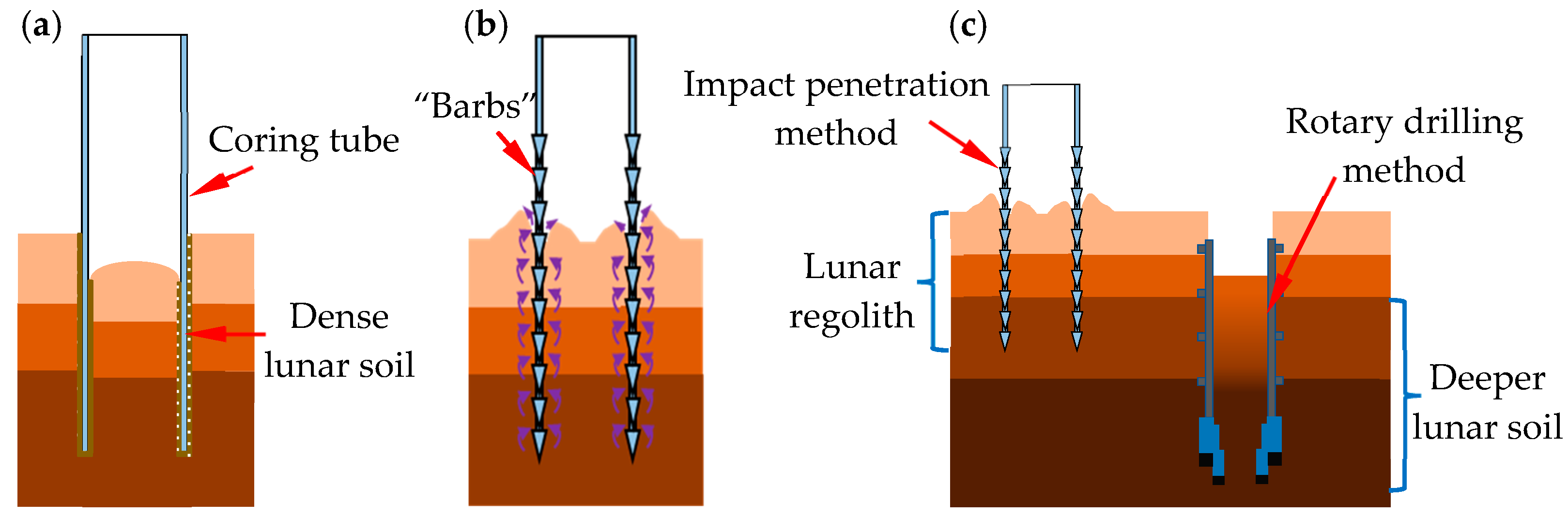
2. Process Analysis of Coring

Currently, there are two methods to obtain lunar regolith samples with stratigraphic information (information on the layering of soil or rock along the vertical direction): impact penetration and rotary drilling sampling. These two sampling methods have advantages and limitations in the lunar surface sampling process. Rotary drilling methods can be roughly divided into single-blade/double-blade spiral drill rod drilling, hollow drill tube drilling, and no-slippage double-tube soft bag drilling [7]. The single-blade/double-blade spiral drilling method (Figure 1a) has a solid rock-breaking ability and high drilling efficiency. However, this coring method completely loses the stratification of lunar regolith samples. The hollow drill tube drilling method (Figure 1b) has a solid rock-breaking ability and high sampling efficiency and can maintain a certain sample of stratigraphic information. However, the rotary motion of the drilling tube causes the sample particles near the inner wall of the drilling tube to mix up and cannot keep the in situ stratigraphic information well [29]. The no-slippage double-tube soft bag drilling method (Figure 1c) has a hollow drill tube with an embedded holding coring tube and an inward-flip soft bag. A soft bag can collect the sample without slippage during sampling, keeping the sample’s stratification [30]. Nevertheless, the mechanism is more complex, and flexible soft bag winding on the small diameter cylinder is bound to squash the force, thus affecting the laminarity of the sample. In addition, during the common drilling and sampling process, the friction between the drilling tool and the lunar regolith and rock generates a large amount of heat, which affects the life of the drilling tool and the quality of the sample [27,31,32]. An in-depth study on the optimal design of drilling tools is needed.
Compared with the rotary drilling sampling method, impact penetration coring has better retention of sample stratigraphic information. The impact penetration method is generally used to obtain lunar regolith samples by manually striking the thin-walled coring tube and making the tube penetrate downward continuously [33]. However, the frequency of manual striking is low, and the squeezing of lunar soil particles near the coring tube generates enormous contact stress. This leads to increased friction between the lunar soil particles and the surface of the coring tube, which increases energy consumption and hinders sample collection, as shown in Figure 2a. It is found that high-frequency dynamic impact can reduce the contact stress between the coring tube and lunar soil particles and drive the lunar soil particles on the surface of the coring tube to move toward the lunar surface. The use of coring tubes with an anisotropic frictional surface profile can further enhance the transport effect of lunar soil particles and thus improve the coring rate [34,35]. The coring tube has wedge-shaped “barbs” on the inner and outer surfaces so that the lunar soil particles near the outer wall of the coring tube are discharged from the lunar surface. In contrast, those near the inner wall of the coring tube are transported upward, keeping the length of the sample consistent with the penetration length of the coring tube, as shown in Figure 2b.
These two sampling methods have their respective advantages and limitations in the process of lunar surface sampling. This study combines impact penetration and rotary drilling to ensure a stable sampling process. When working on the lunar surface, the astronaut or lander provides the feed force for the coring device. Impact penetration sampling is used to maximize the original lunar soil stratigraphy information for sampling the lunar regolith layers. When sampling deeper layers or encountering hard lunar rocks, the astronaut can start the impact penetration module and the rotary module at the same time. The coring tube can be replaced by an auger drilling tube to realize the cutting and drilling action of lunar regolith or lunar rocks to achieve the purpose of deep coring, as shown in Figure 2c.

3. Man-Machine Synergic Lunar Coring Device Scheme Design

3.1. Design Requirements for Coring Devices

Coring devices working on the lunar surface are subject to many limitations of the lunar surface environment. For example, overly complex devices are prone to malfunction during work, so coring devices, especially handheld coring devices, should be simple in structure and easy to operate. In the sampling process, the energy required for sampling the lunar regolith at different depths differs, so the coring device should adjust the impact frequency in real time to improve the sampling efficiency. The sampling methods applicable to lunar soil and lunar rockare different, and suitable sampling methods need to be selected for the sampling environment to improve the sampling success rate. When collecting deep samples, the length of the coring tubes needs to be increased. However, too-long coring tubes are not easily transported and operated by astronauts, which requires multiple sections of coring tubes to be interconnected. In particular, it should be noted that the lunar surface environment is very harsh and unsuitable for astronauts to work outside the landing module for long periods. Therefore, the coring device can be hand-held by the astronaut and quickly installed on the lander or rover for the autonomous operation of the coring.
The man-machine synergic coring device should have the following characteristics:
(1)
Astronauts’ handheld coring device structure should be simple, easy to operate, and low power consumption.
(2)
The coring device should have extremely high stability to ensure that the coring missions are carried out safely and stably.
(3)
The coring device’s impact frequency and energy can be adjusted according to the sampling depth.
(4)
The sampling method of the coring device (impact penetration and rotary drilling) can be changed according to the sampling environment.
(5)
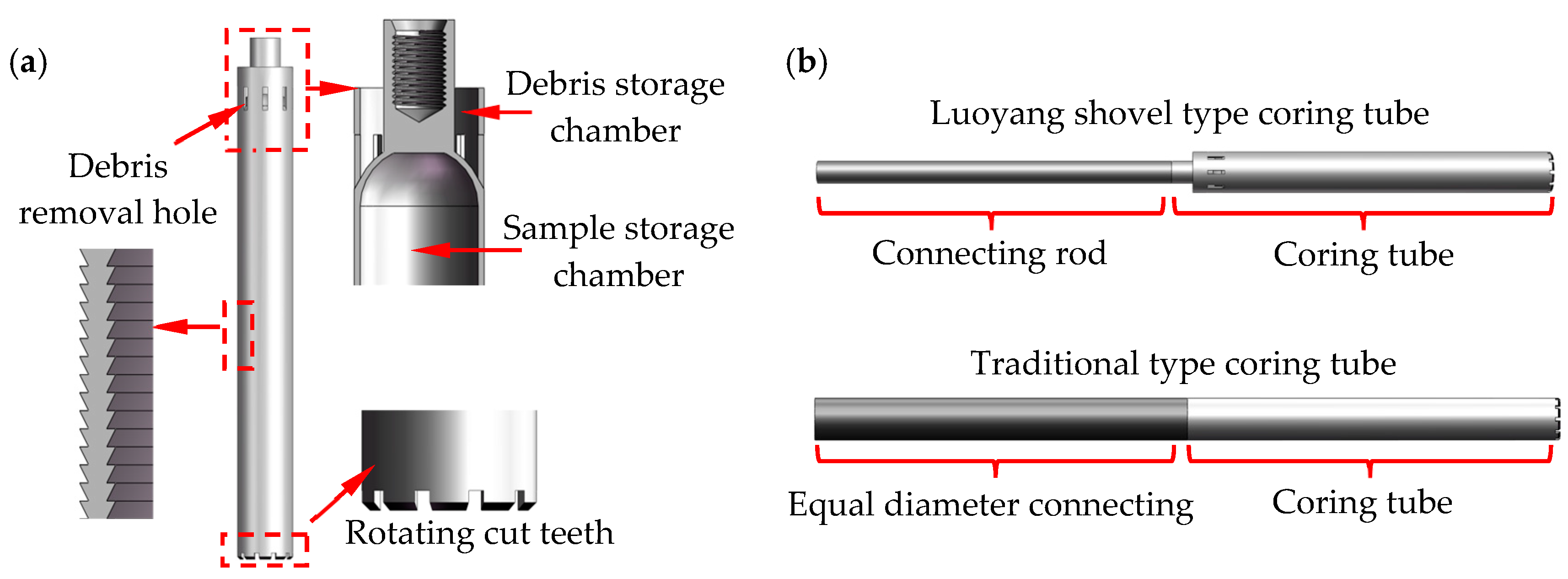
The coring or drilling tube can be assembled freely to achieve depth sampling.
(6)
The handheld coring device is easy to assemble and disassemble and can be mounted on the lander or rover for autonomous operation.
The design parameters of the man-machine synergic coring device were determined by considering the above design requirements and referring to the design parameters of ALSD, as shown in Table 1.

3.2. Structure Design of the Coring Device

3.2.1. Handheld Dual-Mode Coring Device

The dual-mode coring device mainly includes two methods of coring: impact penetration method and rotary drilling method, and its structural composition is shown in Figure 3a,b.
In the process of sampling the loose lunar regolith layer, to ensure the stratification of the lunar regolith sample to the maximum extent, the impact penetration method sampling is selected, which mainly relies on the high-frequency impact mechanism to realize the coring function. The high-frequency impact mechanism consists of a drive motor, drive shaft, cylindrical cam, energy storage spring, cam roller, impact hammer, and stop-rotation slider, as shown in Figure 4a. The cylindrical cam and the impact hammer are connected, and the impact hammer can only move axially along the limit groove under the restriction of the stop-rotation slider. The rotation of the drive shaft drives the impact hammer to continuously apply high-frequency impact energy on the coring connection body to realize the downward impact penetration action of the coring tube. Adjusting the speed of the drive shaft can change the impact frequency of the impact hammer.
When encountering dense layers of lunar soil or hard lunar rocks that cannot be penetrated, the astronauts can activate the rotating mechanism, relying mainly on gearing. The rotation of the gear drives the movement of the rotating barrel, and the coring connector cooperates with the rotating barrel through the slide key, which does not affect its axial movement along the limit slot while rotating with the rotating barrel. The coring connector further drives the coring tube to cut and drill into the denser lunar soil layer, as shown in Figure 4b. If hard lunar rocks are encountered, and the impact penetration method cannot penetrate, the drive motors of the impact mechanism and rotary mechanism are started at the same time. The coring device is converted into rotary-impact drilling and can achieve excellent drilling results by replacing the bottom penetration coring tube with a spiral drilling tube. The working schematic of the astronaut using the handheld dual-mode coring device is shown in Figure 4c.
The coring tube mainly comprises the sample storage chamber and the debris storage chamber. The sample storage chamber keeps the acquired lunar soil samples in the chamber with stratification. In contrast, the debris storage chamber collects the debris generated during sampling to prevent debris from accumulating in the upper part of the coring tube, which affects the downward penetration of the coring tube and recovery of samples. Therefore, it can effectively reduce the power consumption during the sampling process and improve the sampling efficiency. The inner and outer surfaces of the coring tube are treated to produce a serrated shape, and the rotating cutting teeth set at the bottom can realize the rotating penetration action of the dense lunar soil layer. When a single coring operation is completed and the coring tube is lifted out of the borehole, the debris in the chamber will be discharged out of the tube through the debris removal hole. A schematic diagram of the internal structure of the coring tube is shown in Figure 5a. Unlike the traditional equal-diameter coring tube and connecting tube, the diameter of the connecting rod in this design is smaller than that of the coring tube. The coring structure is similar to the Luoyang shovel (a coring tool, the shovel body is semi-cylindrical and can penetrate more than ten meters of stratum, commonly used in archaeology and prospecting and other fields), as shown in Figure 5b. During the coring process, only the coring tube of the whole coring device is subjected to the frictional force of the lunar soil, which reduces the frictional power consumption and improves the sampling efficiency.

3.2.2. Man-Machine Synergic Coring Device

During a manned lunar mission, astronauts face many limitations and hazards [25]. Therefore, to improve the mobility of the sampling mission, this design is based on the handheld coring device, and the man-machine synergic coring device is designed, as shown in Figure 6a. The astronaut attaches the handheld coring device to the lifting device via a quick interface, and the lifting device provides the feed force for the coring process instead of the astronaut. The drive motor controls the rotation of the chassis rotation device where the coring tube and connecting rod are placed and turns the coring tube and connecting rod to the fixed clamping port, as shown in Figure 6b. The movable clamping device transfers the coring tube or connecting rod to the coring port, and the fixed clamping device assists, and the two work together to realize the assembling and disassembling of the coring tube and connecting rod, as shown in Figure 6c.
A comparison of the dimensions and performance of the handheld and man-machine synergic coring devices is shown in Table 2. The man-machine synergic coring device can be used as a landing module for independent coring on the lunar surface. It can also be installed on the lander or rover for remotely operated coring, as shown in Figure 7.

4. Dynamic Analysis and Verification of the Coring Device

The schematic diagram of the impact mechanism is shown in Figure 8a. The cam roller compresses the spring under the action of the contour line of the cylindrical cam and accumulates elastic potential energy. When the cam roller moves to the position of the crest of the cylindrical convex contour line, the elastic potential energy of the spring is released, as shown in Figure 9a. It pushes the follower (cylindrical cam and impact hammer) toward the coring tube at high speed. In turn, the impact sampling of lunar soil or rock is realized.
Since the cylindrical cam moves at high speed, the design should pay special attention to the impact of the cam roller when cutting into and out of the convex profile line. Therefore, the convex profile line is selected as a modified sine curve, which means that the profile equation before and after the cam is a sine acceleration motion curve, and the curve in the middle part is an isokinetic motion curve, as shown in Figure 9b. This ensures that the follower maintains a uniform motion for most of its travel and avoids shocks in the start and end phases of the cam.
To analyze the dynamic and further optimize the structure, a mechanical model between the motor, the cylindrical cam, and the impact hammer was established, and the boundaries of the structural parameters were determined accordingly. Since the impact module achieves energy storage and releases through the cam mechanism, the simplified cam curve is expanded along a straight line for dynamic analysis. The cylindrical cam radius R, spring preload length l0, cam stroke height h, energy storage spring stiffness kc, cam loading section ratio α, and cam roller radius r are all impact module structural parameters in Figure 8b. These partial structural parameters need to be optimized and designed before the prototype is made, resulting in the maximum single-impact work under limited conditions.
The relationship between motor torque and cam shape during energy storage of the cylindrical cam can be obtained from Figure 8b:
M d [ G + k c ( l 0 + l ) ] h π α
where: Md is the rated torque of the motor; l is the current axial displacement of the roller; G is the gravity of the impact hammer.
For the impact hammer drop process, if the friction between the impact hammer and the guide wall is neglected, the equation of state of the impact hammer during release is:
l = g l u n a r + k ( l 0 + l ) m
Since the equation of the profile line before and after the cylindrical cam is a sinusoidal acceleration motion curve, the initial velocity of the impact hammer in the initial motion condition is 0.
l ( 0 ) = l m a x l ˙ ( 0 ) = 0 l ¨ ( 0 ) = g l u n a r + k ( l 0 + l m a x ) m
The differential equation of the state of motion of the impact hammer is obtained from Equations (2) and (3):
l = l m a x + m g l u n a r k + l 0 cos k m t m g l u n a r k l 0
When the cylindrical cam reaches the bottom, i.e., l = 0, the time from release to contact of the impact hammer is obtained as:
t = m k arccos ( 1 l m a x m g l u n a r k + l 0 + l m a x )
To ensure that the impact energy of the impact hammer is effectively released to the coring tube, a certain length of the gentle section is set on the cylindrical cam for the release of the impact energy. If the impact energy is fully released at time t2, the required length of the gentle section of the cam to ensure that the impact energy is fully released before loading is:
l α = π R ( 1 α ) π R λ ( t 1 + t 2 ) + 2 r
At present, the rated torque of the impact module motor is 10 Nm, and the speed is 0~1000 rpm, while the estimated mass is 0.9 kg based on the 3D model of the impact hammer and the cylindrical cam. If 5 ms is reserved for the impact hammer impact energy release process, the boundary conditions for the cam height, spring stiffness, and spring preload length can be obtained from Equations (1) and (4), as shown in Figure 10a,b.
By limiting the size of the structural dimensions under the boundary conditions, the structural design parameters that can achieve the maximum impact energy under the boundary conditions can be found, as shown in Figure 10b. The optimized structural parameters of the impact mechanism are shown in Table 3. After optimization, the theoretical maximum single impact energy can reach 14.9 J, which can realize the impact coring effect well.
Simulation of the impact process of the simulated lunar rock was carried out in ANSYS Workbench according to the optimized in-structure parameters. The coring and drilling tube materials are chosen as steel material, and the simulated lunar rock is taken as sandstone material. The lunar regolith will not be an entirely loose lunar soil, which can be intermixed with fragmented lunar rocks. If coring tools cannot penetrate the lunar rocks, the coring mission will fail. Therefore, the coring device should perform experiments on the coring performance of simulated lunar rocks to ensure the feasibility of the schemes. According to the lunar rock samples obtained at present, the structure and genesis of lunar rocks can be divided into three categories, namely crystalline igneous rocks, breccias, and lunar soils or moon dust. The simulated lunar rocks have similar mineral composition and chemical composition, similar density, shear modulus, mechanical strength, and Poisson’s ratio as the replica of the experimental properties of the lunar samples. The parameter settings of the simulated lunar rock part are shown in Table 4.
According to the current international research on lunar coring devices, it is found that the coring process for lunar surface regolith is relatively simple, requiring only 2~4 J of impact energy, and both the coring tube and the drilling tube can achieve the coring work well. However, in the case of hard lunar rocks, the choice of the coring method is significant for the success of the coring process. Therefore, the focus was on coring simulation experiments for simulated lunar rocks. After setting the material parameters of the model, the coring/drilling tube and the simulated lunar rock have meshed, as shown in Figure 11. For the simulated lunar rocks with fixed constraints around the perimeter, the coring and drilling tubes are subjected to the pressure exerted by the coring device regardless of the coring method used (about 200 N, not considering the pressure exerted by the astronauts). When using the coring tube impact penetration method, a certain amount of impact energy (about 14.9 J) is applied to the coring tube. If the coring tube impact rotary penetration method is used, a certain additional rotational speed (300 rpm) is applied to the coring tube, as shown in Figure 11a. When using rotary drilling for coring, only a certain amount of rotational speed is applied to the drilling tube. The sampling method is converted to impact-drilling, as shown in Figure 11b, where additional impact energy is applied to the drill tube to achieve a more significant impact-crushing effect. After setting various parameters, the simulation analysis was performed for different coring methods.
In the simulation, the impact energy (14.9 J) released by the impact hammer was applied to the coring tube with a loading time assumed to be 5 ms. During the process of impact energy loading, the coring tube has a certain impact effect on the simulated lunar rocks. However, the impact energy alone could not induce significant deformation of the simulated lunar rocks, with a maximum plastic deformation of only 0.029 mm and without the desired impact-crushing effect (Figure 12a). Even if a certain rotation speed is applied based on impact penetration, the crushing effect of the coring tube on the simulated lunar rocks is not very obvious, and the maximum plastic deformation is only 0.042 mm (Figure 12b). The actual geology of the moon is very complex, and the impact penetration method simply cannot penetrate the rock for sampling. Therefore, the coring device must replace the coring tube with an auger tube when facing hard lunar rocks. Compared with the coring tube, the drilling tube has a significant crushing effect on the simulated lunar rocks during rotational drilling, and the maximum plastic deformation of the rocks can reach 0.35 mm within a loading time of 5 ms (Figure 12c). When a certain amount of impact energy (14.9 J) is added to the rotation drilling process, the sampling method will be converted to impact drilling type, and the crushing effect on the simulated lunar rocks will be significantly increased. The maximum plastic deformation of the simulated lunar rocks can be increased to 0.47 mm during the loading period (Figure 12d). Therefore, according to the sampling environment, choosing the appropriate sampling method can improve sampling efficiency, ensuring the work is safe and stable.
In summary, the magnitude of the impact energy (5~15 J) is closely related to the structural parameters of the impact module and the impact frequency. In addition, the impact frequency also affects the response speed of the impact energy. The impact frequency can be adjusted within 0~20 Hz, and the increase in the impact frequency can effectively destroy the formation of internal stress in the coring tube and improve the coring rate. Although the coring tube under the action of impact energy can achieve the sampling of lunar regolith, the simulation results show that the coring tube cannot penetrate the rock. Therefore, only with the combined effect of impact energy and rotation speed can the drilling tube achieve a significant crushing effect on the lunar rock. In addition, the impact frequency and rotation speed are adjustable to suit different sampling environments.

5. Conclusions

In this paper, a scheme is designed for a synergic coring device in a manned lunar landing sampling mission. It can be handheld by astronauts and mounted on a lander or rover to collect deeper lunar soil samples in their original state. The main work and conclusions are as follows:
(1)
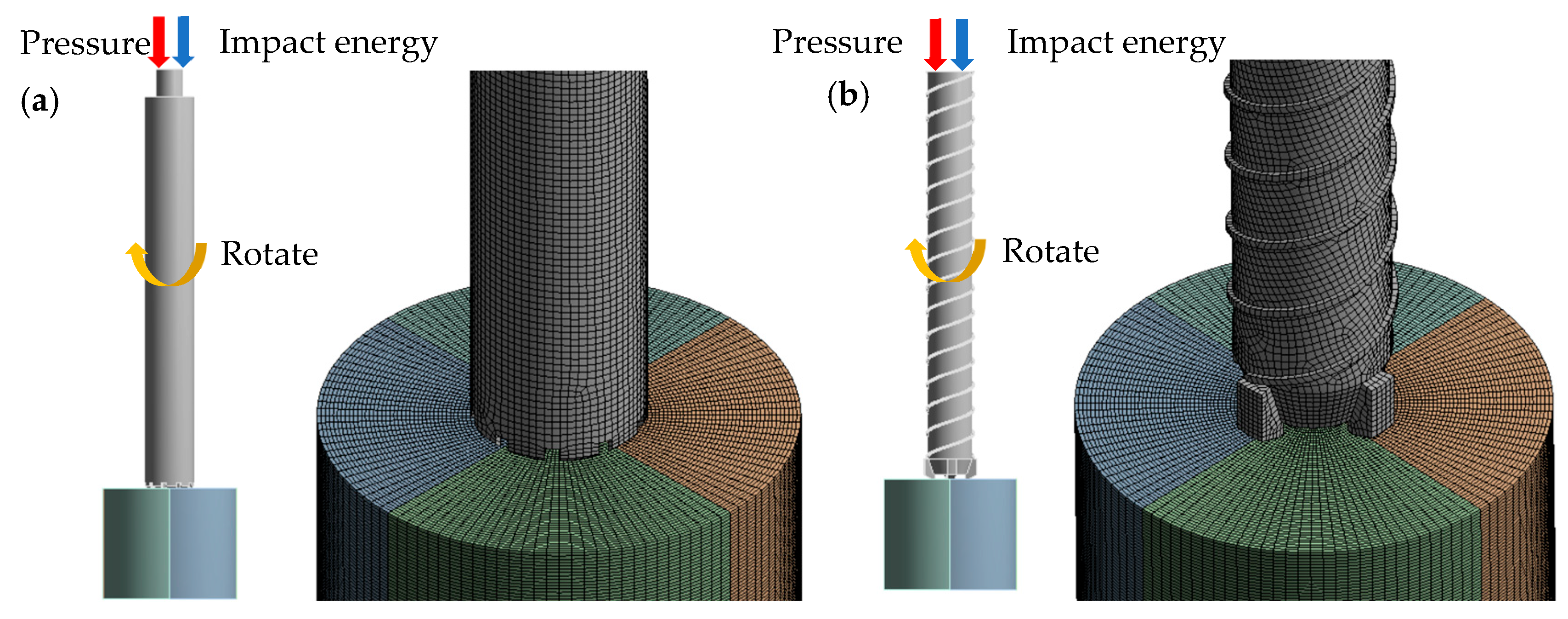
In response to the problem of the low coring rate of the static impact penetration method, a composite coring method of high-frequency impact penetration and rotary drilling coring is proposed. According to the simulation analysis, the impact-rotary drilling method is the more effective way to achieve rock crushing and coring in the lunar regolith.
(2)
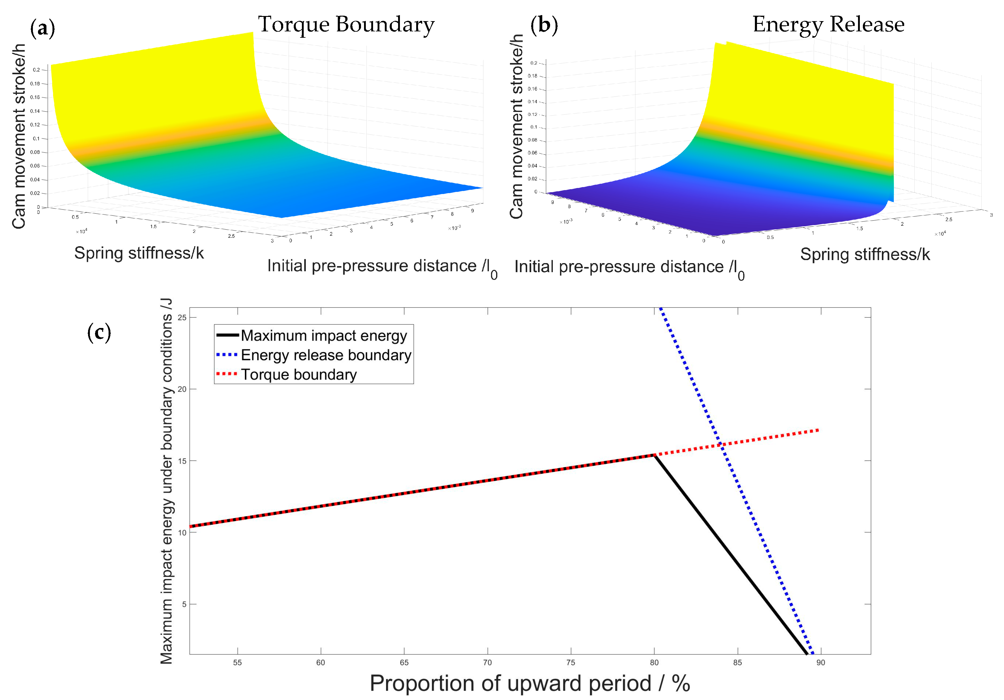
The coring device for astronauts’ handheld operation was designed according to the requirements of coring exploration for the manned lunar landing. The coring device can change the impact frequency (0~20 Hz), impact energy (5~15 J), and rotation speed (0~300 rpm) to adapt to different working environments during the operation. The coring tube and connecting rod can be interconnected to obtain deep lunar soil samples.
(3)
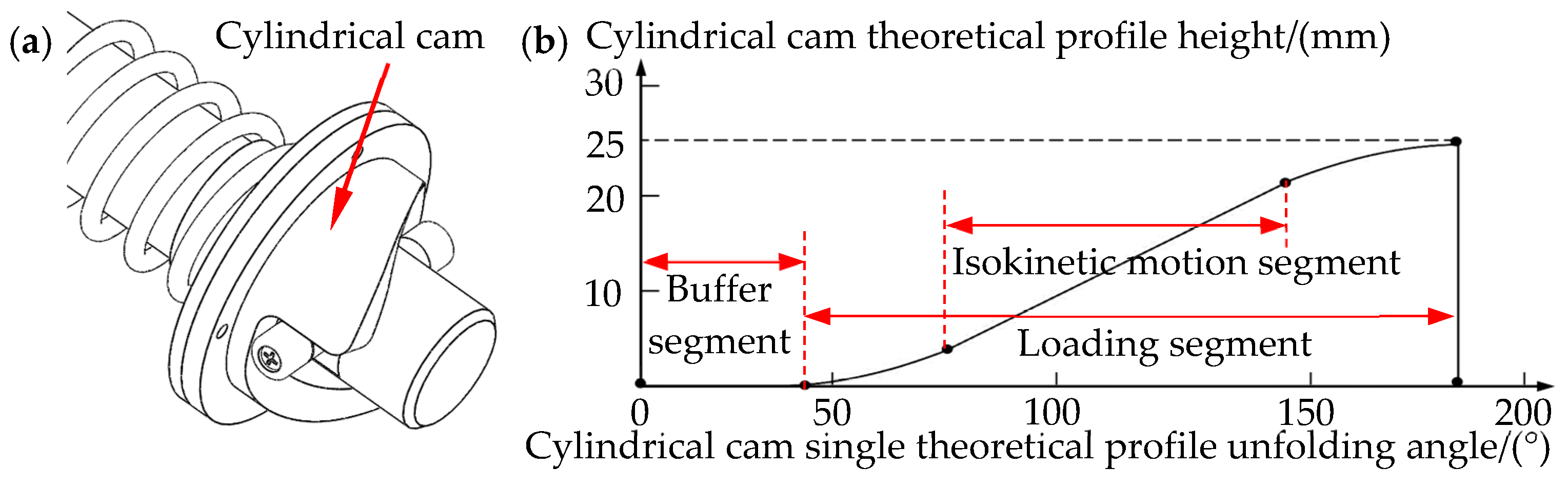
The impact module of the coring device was simulated and analyzed for its ability to crush rocks in the lunar regolith, and the optimal impact structure based on the spring energy storage scheme was determined. Additionally, the impact process is simulated by ANSYS explicit dynamics to determine the impact-crushing effect of the coring device on the lunar rocks. Under the action of the maximum impact energy (14.9 J), it can produce a plastic deformation effect of 0.47 mm on the lunar rocks within a time period of 5 ms.
(4)
Based on the handheld coring device, a man-machine synergic coring device was designed that can be carried on the lander or rover to address the many constraints of astronauts sampling on the lunar surface. This coring device provides more significant drilling pressure and counter torque, significantly reducing the work effort of the astronauts and increasing the sampling depth.
The man-machine synergic coring device has a broad application prospect in the manned lunar landing sampling mission. In future research, the optimized design of a coring device will be carried out to further improve the synergy between the astronaut and man-machine synergic coring devices and achieve the goals of low power consumption, lightweight, and high coring rate.

Author Contributions

X.Z. and G.Z. completed the main research tasks and wrote the manuscript. G.Z. revised the whole manuscript. M.G. proposed the initial ideas and finished deriving the theory related to soil mechanics. Y.W. (Yufeng Wen) and Y.W. (Yaohui Wang) assisted in the design of the mechanical structure. All authors have read and agreed to the published version of the manuscript.

Funding

The work described in this paper was supported by the National Natural Science Foundation of China (Grant Nos. U2013603, 51827901) and the Shenzhen Natural Science Foundation (Grant Nos. JCYJ20220531103614032, 20200826160002001, JCYJ20220818102409021).

Institutional Review Board Statement

Not applicable.

Informed Consent Statement

Not applicable.

Data Availability Statement

Not applicable.

Conflicts of Interest

The authors declare no conflict of interest.

References

  1. Halliday, A.N. Terrestrial accretion rates and the origin of the Moon. Earth Planet. Sci. Lett. 2000, 176, 17–30. [Google Scholar] [CrossRef]
  2. Kenyo, U.; Hasumi, H.; Ogawa, M. Effects of magma-generation and migration on the expansion and contraction history of the Moon. Earth Planets Space 2022, 74, 78. [Google Scholar] [CrossRef]
  3. Kereszturi, A. Polar Ice on the Moon. In Encyclopedia of Lunar Science; Cudnik, B., Ed.; Springer International Publishing: Cham, Switzerland, 2020; pp. 1–9. [Google Scholar]
  4. Spudis, P.D.; Bussey, D.B.J.; Baloga, S.M.; Cahill, J.T.S.; Glaze, L.S.; Patterson, G.W.; Raney, R.K.; Thompson, T.W.; Thomson, B.J.; Ustinov, E.A. Evidence for water ice on the Moon: Results for anomalous polar craters from the LRO Mini-RF imaging radar. J. Geophys. Res. Planets 2013, 118, 2016–2029. [Google Scholar] [CrossRef]
  5. Boazman, S.; Kereszturi, A.; Heather, D.; Sefton-Nash, E.; Orgel, C.; Tomka, R.; Houdou, B.; Lefort, X. Analysis of the Lunar South Polar Region for PROSPECT, NASA/CLPS; Copernicus Meetings: Palacio de Congresos de Granada, Spain, 2022. [Google Scholar]
  6. Slyuta, E. The Luna program. In Sample Return Missions; Elsevier: Amsterdam, The Netherlands, 2021; pp. 37–78. [Google Scholar]
  7. Zhang, T.; Xu, K.; Yao, Z.; Ding, X.; Zhao, Z.; Hou, X.; Pang, Y.; Lai, X.; Zhang, W.; Liu, S.; et al. The progress of extraterrestrial regolith-sampling robots. Nat. Astron. 2019, 3, 487–497. [Google Scholar] [CrossRef]
  8. Wen, Y.; Zhang, G.; Xie, H.; Gao, M.; Zhang, X.; Wang, Y.; Li, C. Design and Dynamic Analysis of the Wire-Line Coring Robot for Deep Lunar Rocks. Appl. Sci. 2023, 13, 1722. [Google Scholar] [CrossRef]
  9. Sun, W.; Wang, Z.; Zhao, Q. Lunar Exploration and Development Vision. Aerosp. China 2020, 21, 28–34. [Google Scholar]
  10. Guardabasso, P.; Paternostro, S.; Bedialauneta, P.; Fonteyne, R. Lunar landing necessary building blocks and good practices for a sustainable development of human lunar activities. Acta Astronaut. 2023, 202, 782–790. [Google Scholar] [CrossRef]
  11. Scherer, L. The Apollo Missions. Highlights Astron. 1971, 2, 125–141. [Google Scholar] [CrossRef] [Green Version]
  12. MacIsaac, D. NASA Returns to the Moon: The Artemis Missions. Phys. Teach. 2023, 61, 239. [Google Scholar] [CrossRef]
  13. Crane, L. A Different Kind of Space Race. New Sci. 2022, 255, 39–41. [Google Scholar] [CrossRef]
  14. Gross, J. From Apollo to Artemis and beyond: How the Apollo Next Generation Sample Analyses (ANGSA) program helps to prepare for future sample missions to the Moon and beyond. In Proceedings of the AAS/Division for Planetary Sciences Meeting Abstracts, London, ON, Canada, 2–7 October 2022; p. 110.103. [Google Scholar]
  15. Xu, L.; Li, H.; Pei, Z.; Zou, Y.; Wang, C. A Brief Introduction to the International Lunar Research Station Program and the Interstellar Express Mission. Chin. J. Space Sci. 2022, 42, 511–513. [Google Scholar] [CrossRef]
  16. Biswal, M.; Malaya, K.; Gomez-Fernandez, D.; Das, N.B.; Kumar V, R. Design Study and Validation of Mars Underground Habitat for Human Settlement on Mars. In Proceedings of the AIAA Propulsion and Energy 2021 Forum, Virtual Event, 9–11 August 2021; p. 3725. [Google Scholar]
  17. Kereszturi, A.; Bradak, B.; Chatzitheodoridis, E.; Ujvari, G. Indicators and Methods to Understand Past Environments from ExoMars Rover Drills. Orig. Life Evol. Biosph. 2016, 46, 435–454. [Google Scholar] [CrossRef] [Green Version]
  18. Yang, H.; Yang, R.; Wang, Q. Laboratory construction and curation scheme for returned samples of the chang’e-5 mission. Geosci. Lett. 2022, 9, 19. [Google Scholar] [CrossRef]
  19. Zhang, T.; Wang, B.; Wei, H.; Zhang, Y.; Chao, C.; Xu, K.; Ding, X.; Hou, X.; Zhao, Z. Review on planetary regolith-sampling technology. Prog. Aerosp. Sci. 2021, 127, 100760. [Google Scholar] [CrossRef]
  20. Zhang, X.; Zhang, G.; Xie, H.; Gao, M.; Wen, Y. A Review of Sampling Exploration and Devices for Extraterrestrial Celestial Bodies. Space Sci. Rev. 2022, 218, 59. [Google Scholar] [CrossRef]
  21. Chen, H.; Li, L.; Cui, Y.; Jiang, S. A novel lunar soil coring approach based on particle unidirectional flow effect to reduce drag and increase efficiency. Adv. Space Res. 2021, 68, 117–133. [Google Scholar] [CrossRef]
  22. Chen, H.; Liu, R.; Ma, C.; Jiang, S. Design of handheld corer for lunar regolith based on particle directional flow method. J. Deep Space Explor. 2020, 7, 164–170. [Google Scholar] [CrossRef]
  23. Sun, F.; Huo, X.; Mao, M.; Zhao, H.; Xu, F.; Zhang, W.; Chen, H.; Tang, J.; Zhang, X.; Liu, Y. Design of Double-Body Vibration Penetration Lunar Soil Sampler by Magnetic Driven. J. Deep Space Explor. 2022, 9, 157–164. [Google Scholar] [CrossRef]
  24. Delp, M.D.; Charvat, J.M.; Limoli, C.L.; Globus, R.K.; Ghosh, P. Apollo Lunar Astronauts Show Higher Cardiovascular Disease Mortality: Possible Deep Space Radiation Effects on the Vascular Endothelium. Sci. Rep. 2016, 6, 29901. [Google Scholar] [CrossRef] [Green Version]
  25. Braddock, M. Hazards of Lunar Regolith for Respiratory, Central Nervous System, Cardiovascular and Ocular Function. Hum. Factor Settl. Moon Interdiscip. Approach 2021, 9, 141–157. [Google Scholar] [CrossRef]
  26. Zacny, K.; Bar-Cohen, Y.; Brennan, M.; Briggs, G.; Cooper, G.; Davis, K.; Dolgin, B.; Glaser, D.; Glass, B.; Gorevan, S.; et al. Drilling systems for extraterrestrial subsurface exploration. Astrobiology 2008, 8, 665–706. [Google Scholar] [CrossRef] [PubMed] [Green Version]
  27. Zhao, D.; Cheng, Z.; Zhang, W.; Cui, J.; Wang, H. Numerical Modeling of Thermal Behavior during Lunar Soil Drilling. Aerospace 2023, 10, 472. [Google Scholar] [CrossRef]
  28. Korotev, R.L.; Haskin, L.A. Some lessons from Apollo for a sampling strategy on Mars for understanding the origin of the ancient igneous crust and the composition of the mantle. In Proceedings of the Lunar and Planetary Institute, Workshop on Mars Sample Return Science, Houston, TX, USA, 16–18 November 1987. [Google Scholar]
  29. Kereszturi, Á.; Duvet, L.; Gróf, G.; Gyenis, Á.; Gyenis, T.; Kapui, Z.; Kovács, B.; Maros, G. Characterization and first results of the planetary borehole-wall imager—Methods to develop for in-situ exploration. Open Astron. 2019, 28, 13–31. [Google Scholar] [CrossRef]
  30. Liang, J.; Tao, L.; Zhang, W.; Tang, J.; Pang, Y.; Jiang, S. Analysis of the lunar regolith sample obstruction in the Chang’E-5 drill and its improvement. Adv. Space Res. 2022, 69, 2248–2258. [Google Scholar] [CrossRef]
  31. Tian, Y.; Zhang, J.; Zhang, W.; Xu, B.; Duan, Z. Drill-soil penetration model and its application to lunar exploration. Adv. Space Res. 2022, 70, 3436–3449. [Google Scholar] [CrossRef]
  32. Xu, J.; Yuan, X.; Zhang, Y.; Yu, S.; Pang, Y.; Zhang, T.; Xu, K.; Ding, X. Real-time prediction of drilling forces inside lunar regolith based on recurrent neural networks. Acta Astronaut. 2022, 201, 259–273. [Google Scholar] [CrossRef]
  33. Zhao, D.; Cheng, Z.; Zeng, K.; Hu, M.; Gao, X. Optimized design of high-efficiency lunar soil sampling tube structure based on stress–strain law. Adv. Space Res. 2023, 71, 2128–2139. [Google Scholar] [CrossRef]
  34. Gao, Y.; Ellery, A.; Jaddou, M.; Vincent, J. Deployable wood wasp drill for planetary subsurface sampling. In Proceedings of the 2006 IEEE Aerospace Conference, Big Sky, MT, USA, 4–11 March 2006; p. 8. [Google Scholar]
  35. Gao, Y.; Ellery, A.; Jaddou, M.; Vincent, J.; Eckersley, S. Planetary micro-penetrator concept study with biomimetric drill and sampler design. IEEE Trans. Aerosp. Electron. Syst. 2007, 43, 875–885. [Google Scholar] [CrossRef]
Figure 1. Rotary drilling method diagrams. (a) Single-blade/ double-blade spiral drill rod drilling; (b) Hollow drill tube drilling; (c) No-slippage double-tube soft bag drilling.
Applsci 13 07961 g001
Figure 2. Impact penetration method diagrams. (a) Impact penetration coring; (b) Impact penetration coring after morphologic treatment; (c) Schematic diagram of the dual-mode coring method.
Applsci 13 07961 g002
Figure 3. (a) Schematic diagram of the handheld dual-mode lunar coring device; (b) Handheld coring device module composition diagram.
Applsci 13 07961 g003
Figure 4. (a) Schematic diagram of the structure of the high-frequency impact module; (b) Schematic diagram of the structure of the rotating module; (c) Schematic diagram of the coring process of the handheld coring device.
Applsci 13 07961 g004
Figure 5. (a) Schematic diagram of the structure of the coring tube; (b) Comparison of Luoyang shovel-type coring tube and traditional coring tube.
Applsci 13 07961 g005
Figure 6. (a) Overall structure of the man-machine synergic coring device; (b) Internal diagram of the man-machine synergic coring device; (c) Clamping device of the man-machine synergic coring device.
Applsci 13 07961 g006
Figure 7. Schematic diagram of the sampling pattern of the coring device. (a) Man-machine synergic coring; (b) Astronaut handheld coring; (c) Coring device mounted on the lander; (d) Coring device mounted on rover.
Applsci 13 07961 g007
Figure 8. (a) Schematic diagram of the impact mechanism; (b) Force analysis diagram of the cylindrical cam.
Applsci 13 07961 g008
Figure 9. (a) Schematic diagram of cylindrical cam; (b) Cylindrical cam curve expansion diagram.
Applsci 13 07961 g009
Figure 10. (a) Torque boundary conditions for structural parameters of the impact module; (b) Energy release boundary conditions for structural parameters of the impact module; (c) Maximum impact energy under boundary constraints.
Applsci 13 07961 g010
Figure 11. Parameter setting and meshing of the coring model (a) Impact penetration method; (b) Rotary drilling method.
Applsci 13 07961 g011
Figure 12. Crushing effects on simulated lunar rocks under different conditions (Strain, mm) (a) Coring tube under impact; (b) Coring tube under impact and rotation; (c) Drilling tube under rotation; (d) Drilling tube under impact and rotation.
Applsci 13 07961 g012
Table 1. Design parameters of the coring device.
ItemsImpact FrequencyImpact EnergyRotational SpeedSingle Tube LengthInner Diameter of Coring TubeCoring Rate
Parameters0~20 Hz5–15 J0~300 rpm350 mm40 mm 85%
Table 2. Performance comparison of the handheld coring device and man-machine synergic coring device.
Outline   Dimension / mm   ( L   ×   W   ×   H Weight/kgMaximum Input Power/kwEffective Sampling Depth/m
Handheld coring device400 × 210 × 380 25 1.5 2
Synergic coring device820 × 800 × 1400 150 4 3
Table 3. Relevant parameters of the optimized impact structure.
Motor Torque Md (Nm)Impact Frequency
λ (Hz)
Cam Height
h (mm)
Preload Height l0 (mm)Spring Elastic Stiffness
k (N/m)
Impact Mass
m (kg)
1020251030,0000.9
Table 4. Basic physical and mechanical parameters of simulated lunar rock.
Density
ρ (kg/m3)
Shear Modulus
G (GPa)
Tensile Strength
T (MPa)
Compressive Strength
fc (MPa)
Modulus of Elasticity
E (GPa)
Poisson’s Ratio
ν
21644.4371.10770.2712.270.38
Disclaimer/Publisher’s Note: The statements, opinions and data contained in all publications are solely those of the individual author(s) and contributor(s) and not of MDPI and/or the editor(s). MDPI and/or the editor(s) disclaim responsibility for any injury to people or property resulting from any ideas, methods, instructions or products referred to in the content.

