1. Introduction
One of the critical issues related to a EUROfusion R&D DEMO strategy is to find an innovative solution for the breeder blanket layouts that are capable of fulfilling main system requirements on (a) tritium breeding capacity, (b) energy deposition, (c) safety, and (d) reliability [
1]. The first one implies tritium generation per one plasma source neutron exceeding unity, i.e., tritium breeding ratio (TBR), with a margin sufficient to account for tritium losses in the fuel cycle and to assure arrangement in a DEMO tokamak of all auxiliary systems and cut-outs such as limiters, plasma heating systems diagnostic equipment, etc., decreasing blankets first wall area. To address this issue, the “required TBR”, TBR
req, was introduced, assuming a full coverage of the first wall with breeder blankets without any cut-outs in the first wall. Depending on the technology adopted for the tritium fuel cycle, the TBR
req can significantly vary, TBR
req = 1.13 ÷ 1.16 [
2], the TBR
req = 1.16 being the most conservative estimation. The second option assumes achieving sufficient energy generation in the blankets to demonstrate the feasibility of the DEMO reactor as a reliable and safe energy source. Regarding safety issues, the blanket design should ensure the secure integrity of its structure during routine operation and transition processes and also prevent infiltration of radioactive substances (tritium, radioactive products, etc.) in a primary cooling system. As for reliability, the blanket should be simple enough in order to be built with the minimum number of elements, including welds acting against leakage of pressurized fluids, to minimize its failure rate.
As accepted in the EUROfusion DEMO project, the breeder blanket design development follows a strategy that aims at achieving the maximum TBR for a geometry layout under elaboration. The achievement of the TBR ≥ TBRreq is a prerequisite to ensure the tritium sustainability of the DEMO fuel cycle that, in the end, could make the whole project more economically and publicly acceptant. This assumes intensive optimization work of the design to adjust the blanket performances, such as TBR, material temperatures, and thermal stresses in the constructions, to the project limitations and requirements. Within this frame, the modifications that can be applied to the geometry layout become the most important to find an optimal blanket configuration. The optimization procedure may also include a variation of the materials used for the design. These two options are the main tools to achieve the robust blanket geometry layout that satisfies the system requirements.
Two different concepts are now in progress and selected to be a driver blanket for the DEMO fusion reactor: WCLL (Water-Cooled Lithium Lead) [
3] and HCPB (Helium-Cooled Pebble Bed) [
4]. Because of the different reactor technologies and materials utilized, these two concepts have their own cons and pros affecting EUROfusion R&D activity, respectively. Pressurized water (155 bar) assumed in the cooling system of the WCLL DEMO, even in spite of complex chemistry, seems to have some advantages compared to helium gas coolant: the technology is cheap, well-established, and robust. Liquid lead being used as a neutron multiplier is widespread and not expensive. Weak points in the WCLL blanket concept are corrosion between PbLi eutectic and steel structure, a tritium permeation from PbLi through steel walls in the water coolant, and an immature tritium extraction technology. These technological issues are out of the scope of this work, and they are not addressed in the paper. A solid breeder used in the HCPB blanket provides efficient tritium generation, and its extraction from the helium purge gas is technologically feasible and industrially scalable. The main disadvantages of the HCPB blanket are the cost of the neutron multiplier (Be
12Ti) and a high-pressure (80 bar) helium primary cooling loop that assumes a ramified pipe system and big heat exchangers.
The research efforts in the WCLL blanket developments are concentrated on alternative solutions to improve its efficiency, safety, and reliability. This assumes the development of new schemes of the blankets layouts using basically the same materials but leading to more efficient tritium generation and also to the higher energy deposition in the blankets. To this end, an alternative and promising design was proposed and elaborated for the WCLL concept enabling it to meet the requirements for the efficient blanket design discussed above. This concept, WCLL-db (WCLL-double bundle) [
5], can potentially provide a more rational use of the blanket volume for tritium generation compared to the reference WCLL design.
A promising solution for the blanket design could also be potentially gained as a combination of the benefits of the driver blankets concepts: (1) the use of the solid breeder for the tritium generation, (2) the liquid lead neutron multiplier, and (3) pressurized water coolant. This WLCB (Water-cooled liquid Lead Ceramic Breeder) concept represents a trial to replace a very expensive Be12Ti neutron multiplier used in the HCPB breeder blanket concept with the less effective but much cheaper Pb one to solve a problem with a Be supply for DEMO needs. Such breeder blankets would have the potential to operate in two modes: with and without liquid lead circulation. The former is similar to the operation scenario of the reference WCLL DEMO blanket, and the latter assumes the blanket without liquid metal circulation in the external loop. The second option is much more attractive from the DEMO design point of view: it saves reactor space and makes the whole project significantly cheaper. However, a choice between these options could be made only after detailed nuclear, thermal, and safety analyses.
This paper presents an assessment of the main nuclear responses of the WCLL-db and WLCB breeder blankets necessary to support R&D work aimed at a consolidated blanket design. Such activity assumes the implementation of several work steps with a final goal of developing a suitable geometry model of the DEMO with breeder blankets arranged in the plasma chamber and carrying out numerical simulations. This procedure is well-established and implies a logical sequence of the developments and research activities providing robust geometry models that ensure high-fidelity results of the neutronic simulations. The workflow has several milestones: development of the CAD geometry model for the blankets, conversion of these models into an MCNP geometry representation, elaboration of the MCNP input deck, MCNP simulations, and analysis of the results.
2. WCLL-db Blanket Study
2.1. CAD Geometry Models for WCLL-db Blankets
2.1.1. WCLL-db Blanket Layout
A preliminary CAD design elaborated for one WCLL-db blanket,
Figure 1, serves as a basis for the neutronic model’s development. The WCLL-db blanket was developed to have a Single-Module-Segment casing composed of a U-shaped first wall (FW) and a manifold or a collector with a 50 mm thick back supporting wall (BSW). The 12 mm thick vertical stiffening plates connecting the BSW and the FW secure the integrity of the blanket. A liquid PbLi eutectic (Pb15.7Li, 90%
6Li enrichment) is fed through a chimney attached to the back supporting wall; it passes the manifold and then goes up to an upper spreader. A breeder zone (BZ) of the WCLL-db is cooled similarly to the reference design [
3] by the pressurized water (155 bar) with 290 °C and ~320 °C temperature in the inlet and the outlet channels, respectively. Water pipes in the BZ are made of Eurofer steel, and they are combined in several poloidal blocks with separate inlet and outlet feeding pipes. The water pipes have a double bundle structure with central water and outer presser tubes. A gap between the central and the pressure tube helps to avoid contact between the water and the PbLi in case of rupture of the inner water tube. The gap is filled with PbBi in order to ensure heat transfer from the PbLi to the water chamber. Such a double bundle structure also serves to minimize the tritium permeation from the PbLi eutectic into the water coolant. The FW is made of Eurofer, and it is supposed to have three layers: an 18 mm thick plasma-faced layer with cooling channels, a 2 mm PbBi separating safety layer similar to the double bundle water tubes, and a 5 mm back layer. Thus, the plasma-facing part of the FW has a 25 mm thickness in total. The side walls of the FW are planned to be thicker to ensure the blanket integrity: the first layer facing the gap between blankets is 43 mm thick, followed by the 2 mm PbBi layer and 5 mm steel back layer to make up 50 mm thickness in total. The plasma-faced surface of the FW is covered with 2 mm tungsten armor. The manifold made of Eurofer steel has three radial chambers filled with pressurized water. It has 220 mm radial thickness on both the inboard (IB) and outboard (OB) sides. Two front 30 mm thick walls form the 5 mm thick camera filled with PbBi eutectic. The BZ radial thickness in the reactor mid-plane is 440 mm and 645 mm on the IB and OB sides, respectively.
2.1.2. CAD Model for the Neutronic Simulations
The CAD geometry model of the WCLL-db blanket suitable for the neutronic calculations should include all essential elements affecting particle transport simulations and providing finally high fidelity nuclear responses that can be directly compared to those obtained within the WCLL blanket R&D project. Therefore, this CAD geometry model includes simplifications of the same degree that were adopted in the WCLL CAD blanket model, and it also encloses enough heterogeneity in the geometry resulting in such representation of the layout that adequately reflects the original WCLL-db blanket design.
The approach adopted in this work assumes a decomposition of the original CAD blanket model in several main parts: the first wall, the cooling pipes with the stiffening plates, and the manifold,
Figure 1. Initially, all geometry parts include some complexities preventing their direct use for the model’s conversions into the MCNP geometry representations: the CAD models enclose spline geometry surfaces, geometry cells are not grouped according to materials assignments, and these models appeared to be not free from geometry errors, for example, overlapping of the cells. Therefore, significant efforts were spent on replacing all spline surfaces found in the models with surfaces of the first and the second order, such as plane, cylinder, sphere, cone, and torus. Special attention was paid to the precise fitting of the original surfaces with the new ones.
As mentioned above, specific simplifications were introduced in the CAD models to make possible the elaboration of the geometry for the neutronic calculations. Excessive fine geometry details left in the CAD blanket models could result in a complex input deck that significantly increases the probability of failure during geometry conversion and then in the particle transport calculations. Shown in
Figure 2 is the simplification of the FW introduced in the CAD models of the WCLL-db blankets. Similar to the WCLL model for neutronic simulations, the modified FW does not include chamfers in the corners. This simplification slightly increases the BZ volume and the TBR, respectively. This effect is addressed in
Section 2.3.1. The double-bundle tubes having originally long free-body shapes were replaced with cylinders following very closely the original cooling tube shapes,
Figure 2.
The original CAD model provided for the current work did not include definitions of the materials or the substances filling various pipes, the manifolds, and the BZ itself. In the approach assumed in the original CAD models, the filler of these channels or big cells should be defined during geometry modeling for the neutronic simulations. To this end, these geometry cells filling all pipes, tubes, channels, etc., were newly introduced in the CAD models. The geometry cells that belong to the same material are grouped together separately in the models.
The DEMO baseline 2017 [
6] includes 16 toroidal segments (22.5°); each segment contains two IB blankets, two lateral and one central OB blanket. Initially provided for the current work was the CAD model for the OB lateral blanket. The CAD geometry models for the IB and OB central blankets were developed using patterns, i.e., the same geometry solutions implemented in the OB lateral blanket model.
The U-shaped first wall of the WCLL-db blanket,
Figure 3, holds water cooling channels of 7 × 7 mm size with 13.5 mm pitch. This layout was accepted from the reference WCLL design. Because such a dense arrangement of the cooling channels was already proven excessive [
3], the layout with the six channels per 135 mm height was adopted in the WCLL-db project, similar to the WCLL-db one.
2.2. Development of the WCLL-db MCNP Geometry Model
2.2.1. CAD to MCNP Geometry Model Conversion
The CAD to MCNP geometry model conversion for particle transport calculations was performed with SuperMC code [
7]. To ensure reliable conversion, the CAD models for WCLL-db blankets were developed to avoid, if possible, tori surfaces. Although torus can be successfully used in the MCNP geometry models, the model of the WCLL-db blanket originally includes hundreds of tori, which very likely leads to numerous geometry errors in the converted models.
The most crucial procedure in the model conversion is the generation of the void cells. In the MCNP code used in the fusion-related tasks, geometry cells must be complemented with the void cells describing a space around them. Void cells are generated in the SuperMC, making use of Boolean operations that are less robust compared to direct processing of the solid surfaces from the CAD model. In the case of numerous tori available in the geometry model, the probability of the malfunction of the code drastically increases. As a result, the model can include geometry errors disabling calculations. A manual post-correction of the geometry model is not possible due to its complexity. This happens because void cells can be too complex, and their boundaries could be formed by many tori surfaces.
To avoid errors in the MCNP geometry, the CAD models are divided into several (smaller) parts, for example, the first wall, the collectors, and the pipes bundles. This approach was described above. Such treatment has two main advantages: (1) the smaller models, even with tori included, can be reliably converted, and (2) to modify the design, it is enough to modify the small constituent part rather than a whole blanket model. For each blanket, three stand-alone MCNP geometry models were generated representing the FW, the manifold, and the BZ with the bundles of the water cooling tubes. Each model was checked against geometry errors by making use of the MCNP cell volumes calculations. A few insignificant and tiny geometry errors were detected in the models, the number of lost particles not exceeding a few (<5) per 107 source neutrons. If a deviation from this criterion has been found, the location of the geometry errors was fixed, and the initial CAD model was corrected accordingly.
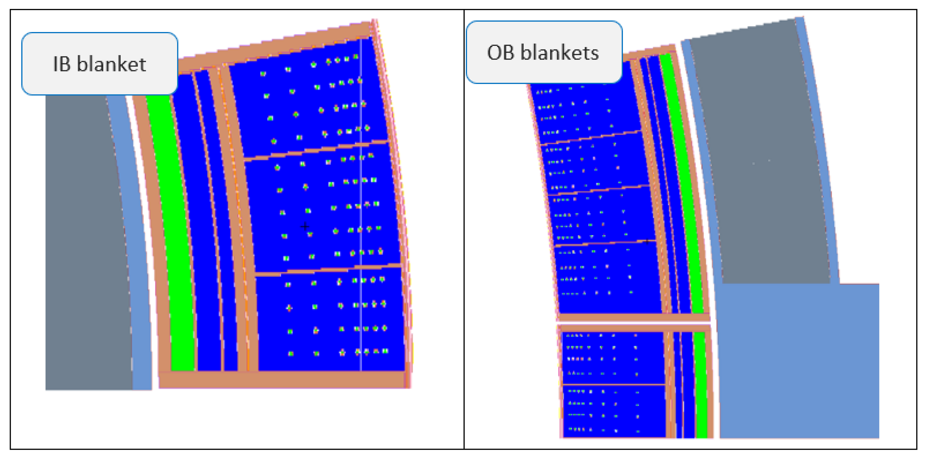
2.2.2. MCNP Geometry Model
The WCLL-db MCNP geometry models were built on the basis of the DEMO 2017 baseline model with an empty breeder blanket space [
8]. Half of the 22.5° (11.25°) toroidal segment was used to accommodate the newly elaborated MCNP geometry models of IB and OB blankets. To simulate DEMO, 360° torus reflecting boundary surfaces were assigned to the segment. The WCLL-db MCNP model has a modular structure that follows hierarchy rules for different parts of the whole blanket model. A unique universe number was assigned to each local MCNP module. The MCNP model of the blanket,
Figure 4, is built in sequential order of the modules filling the whole blanket space. This assumes a strict hierarchy of universes: (1) empty breeder blanket space from DEMO baseline model → (2) first wall → (3) collectors and breeder zone → (4) pipes bundles. Such a modular system enables quick modifications of the design without destroying the whole geometry because each universe is originally the independent MCNP model of the different blanket components. Nevertheless, prompt modifications of the model are limited to the very simple ones: global materials replacement and local geometry variations. Any global geometry change requires repetition of the whole procedure of the MCNP model generation, and thus they are considered unreasonable and meant to be avoided. The MCNP geometry model of the WCLL-db DEMO includes all necessary heterogeneous details,
Figure 4, to perform high-fidelity particle transport simulations. Before starting the calculations, the MCNP model was well-tested against geometry errors. The lost particles were detected far away from the plasma outside the vacuum vessel, and their number did not exceed 1 per 10
6. Additionally, all these geometry errors come from the generic model used for the modeling rather than the new blanket descriptions.
Materials assignments for PbLi, Eurofer, and tungsten were already performed in the MCNP input deck using standard definitions adopted within the EUROfusion DEMO project [
9]. For PbBi, a liquid eutectic with a material density of 10.5 g/cm
3 and a 44.5 at%/55.5 at% percentage of Pb and Bi in the mixture were adopted for calculations. The breeder zone volume filled with PbLi has a very complex cell structure due to the presence of numerous water-cooling pipes. The hundreds of geometry cells making up this volume were generated in the SuperMC originally as void cells, and during the preparation of the MCNP input deck, they got the proper material assignment reflecting PbLi properties.
2.3. Results of the Neutronic Simulations for the WCLL-db DEMO
2.3.1. The Main Nuclear Responses
The particle transport simulations were carried out using the geometry model discussed above and MCNP6.2 [
10] code with nuclear data from the JEFF-3.3 library [
11]. The plasma neutron source was simulated within a subroutine [
12] linked to the MCNP during its compilation. Statistical uncertainty of the MCNP nuclear responses does not exceed 0.01% for the TBR and less than 0.1% for other nuclear responses. The most essential nuclear response, TBR, was assessed for the new WCLL-db DEMO concept with a view to examining the tritium breeding performance of the promising layout of the PbLi-based blanket to compare the results with those from the reference WCLL design. The TBR was found to be TBR = 1.16, which is higher compared to the reference WCLL TBR = 1.14 [
3], and it fits the DEMO TBR requirement. Optionally, the water manifold in the WCLL-db blanket could be further squeezed by 20 mm more, increasing the BZ and the TBR, respectively. This possibility was not studied because it should be first checked in the thermal-hydraulic calculations. The PbBi separating layer used in the blanket design in the cooling bundles and the first wall could be alternatively filled with noble gases such as helium, neon, etc. The choice of helium is technologically preferable due to its well-developed technology. In this case, no noticeable TBR reduction was found. As it was discussed above, the level of the simplifications applied to the CAD model of the WLCB-db blanket conforms to those adopted in the WCLL design project. The square edges of the FW used in the model instead of the round shape could reduce TBR not more than ΔTBR < −0.005; this result was obtained in a specially addressed study. This estimation is valid for both WCLL and WCLL-db blankets. All particle transport calculations presented in this work were performed by default with the nuclear data from JEFF-3.3 prepared for 0 °C. The WCLL blanket will operate at higher temperatures, for example, ~310 °C for PbLi or water coolant. The steel structure in the blanket (especially the FW) has even higher temperatures. To simulate rough temperature distributions in the blanket and assess the temperature effect on the nuclear responses, two sets of the JEFF-3.3 nuclear data were used for such calculations: 900 K for the FW and 600 K for the rest of the blanket. The material densities in different geometry cells were adjusted respectively. A slight reduction of the TBR was found by accounting for the temperature effects in the nuclear data, δTBR < −0.5%.
Thermal-hydraulic simulations performed to get a first-guess layout of the WCLL-db blanket were based on the results of the neutronic simulations performed for the reference WCLL blanket [
3,
13]. For the new WCLL-db design, the updated results for integral power generation in the blankets and radial profiles of the nuclear power densities are necessary to confirm or update the blanket layout. To this end, this information was provided for the midplane of the OB blanket, where the energy deposition achieves its maximum. Using these data and an FW neutron load profile [
14], the energy depositions can be restored in all poloidal positions in the IB and OB blankets. The results for the nuclear power generation in different materials of the OB blanket are shown in
Figure 5. An increase in the power densities in the manifold region comes from neutron moderation and absorption in water resulting in an increase of gamma irradiation there. Presented in
Table 1 are the results for the nuclear energy generated in the WCLL-db blankets compared to the data obtained for the reference WCLL DEMO [
13].
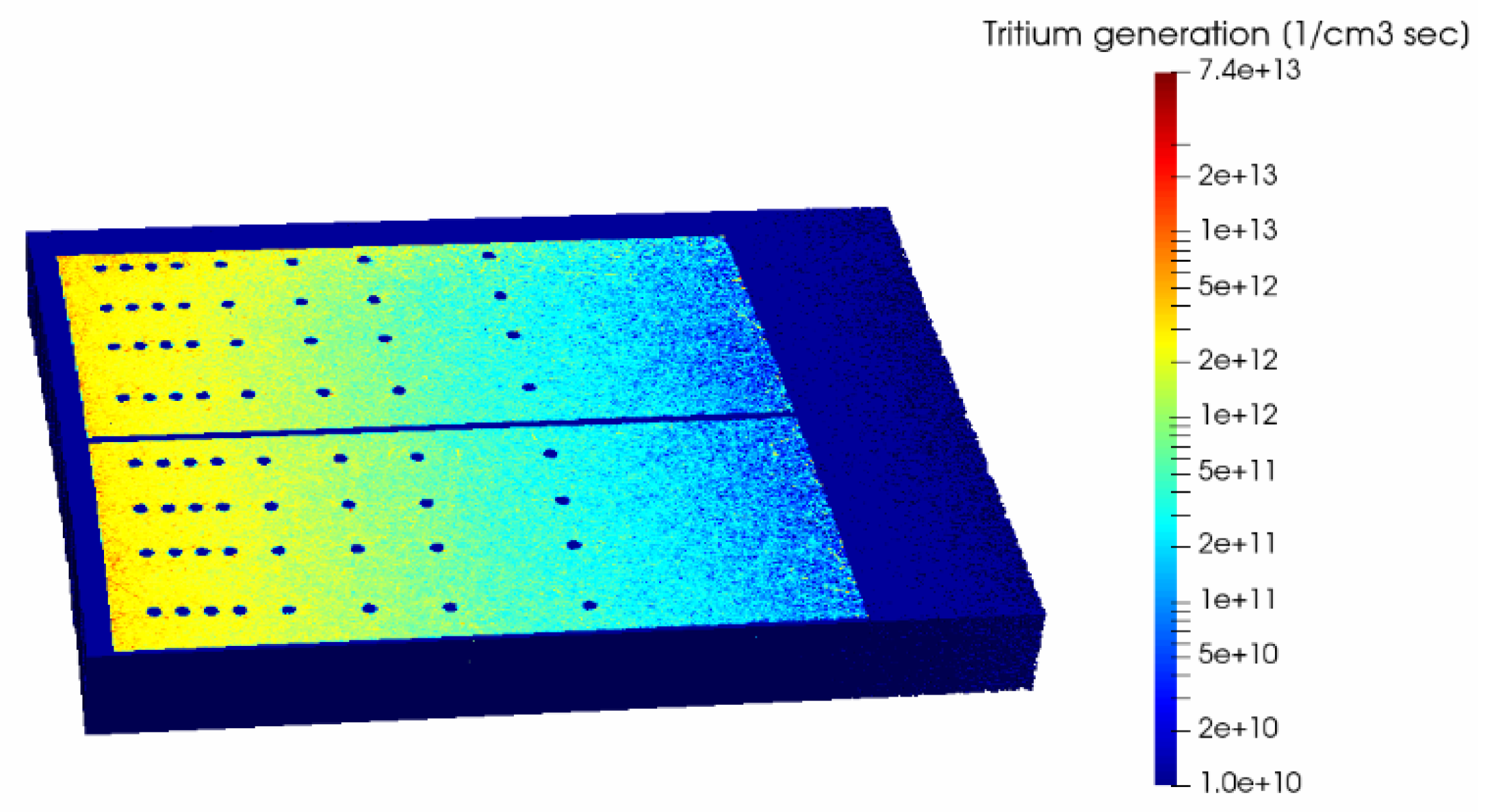
Shown in
Figure 6 is a (n,t) reaction rate calculated on the OB side in the mid-plane of the reactor. Tritium generation in the WCLL-db blanket decreases in the BZ by almost two orders of magnitude in the radial direction. Therefore, the rear part of the BZ contributes only marginally to the TBR. The further radial increase of the BZ by a few centimeters up to 80 cm radial depth could contribute only marginally, i.e., 1 ÷ 2% in the TBR.
2.3.2. Safety Aspects of the PbBi Use in the WCLL-db Blanket
The PbBi (
Tmelt = 123.5 °C) eutectic implemented as a separating layer between water and PbLi in the double-bundle cooling tubes has an inherent safety risk for the environment because of
210Po generation in Bi under neutron irradiation.
210Po is a result of neutron capture reaction on
209Bi (100% in natural Bi) with the production of
210Bi (T
1/2 = 5.01 days) that then decays to α-radioactive
210Po (T
1/2 = 138.38 days). Polonium is highly volatile and readily evaporates from the PbBi eutectic inducing significant surface contamination of the primary cooling loop [
15].
210Po is extremely toxic; this and other polonium isotopes are some of the most radiotoxic substances to humans. With one microgram being more than enough to kill the average adult,
210Po is 250,000 times more toxic than hydrogen cyanide by weight. It is also thought that one gram of
210Po is enough to kill 50 million people and sicken another 50 million [
16]. Therefore, a special study was carried out within this work in order: (1) to demonstrate the potential environmental risk of the PbBi use in the WCLL-db blanket in the case of, nevertheless, acceptance of this material in its design and (2) to indicate alternative compounds that could replace PbBi without a loss of the blanket functionality.
A number of additional calculations were done to demonstrate the alternatives to the use of PbBi eutectic in the WCLL-db blanket. The results of the TBR simulations with the replacement of PbBi in the WCLL-db blanket with various Pb-based compounds [
17] are given in
Table 2. The replacement of the PbBi with the compounds listed in
Table 2 does not result in the reduction of the TBR compared to the layout case with a 220 mm radial thick manifold. All these compounds have a melting temperature much higher compared to the one of PbBi (123.5 °C), which could be a design safety issue in case of their prompt solidification. Therefore, these results obviously cannot be directly used for the design changes because technological aspects of the use of these compounds in the blanket must be investigated first. In spite of this, the main message of these results is to demonstrate the replicability of PbBi in the WCLL-db without loss of its tritium breeding performance. In case of the need, such analyses could be continued.
In the case of the WCLL-db design will be accepted without the PbBi replacement, the accumulation of
210Po in the blanket must be assessed and compared with some safety limits available so far for
210Po contamination. For this purpose, an activation analysis of the irradiated WCLL-db blanket was performed using the automated procedure [
18].
The activations calculations were performed only for the irradiated PbBi eutectic in the IB and OB blankets. Neutron flux intensities and spectra presented with CCFE 709-group structure for activation analysis [
19] were computed with MCNP6.2 utilizing JEFF-3.3 transport data. A mapping of the neutron spectra was done in different geometry cells containing PbBi inside the blanket structure. The statistical uncertainty in all calculations of the total neutron flux does not exceed 1%. For some low energy bins, for instance, 1·10
−7~1·10
−4 MeV, the relative error was found to be as high as ~10%. Normalization of the nuclear responses was done to the DEMO fusion nuclear power of 1998 MW that resulted in 7.094 × 10
20 n/s plasma neutron source intensity. To facilitate the analyses, a code interface was applied for numerous activation calculations. This computer interface is based on MCNP code for particle transport simulations and FISPACT II code for activation inventory analysis of the irradiated materials. FISPACT II code makes use of the TENDL activation data library, and the TENDL-2019 [
20] was used for the current simulations. The inventory results of the FISPACT outputs are collected by a multi-faceted post-processing code.
For the activation calculations, the following irradiation scenario is assumed: during the first 5.2 years minus 10 days, the DEMO is supposed to operate at an average level of 30% total fusion power in the last 10 days 48 pulses of 4 h at 100% fusion power and 1 h dwell time are considered [
21].
The total accumulation of
210Po in all WCLL-db blankets of the DEMO tokamak appeared to reach ~500 g after the shutdown of the reactor, and this amount remained almost unchanged for 30 days afterward. Available human data [
22] define occupational
210Po limits as follow: 680 pg (picograms) with oral ingestion and 130 pg with inhalation. The amount of the accumulated
210Po permits to assess roughly the risks for its intake (in case of even minimal impurity) by personnel during manipulations with equipment or maintenance as potentially extremely high. Obviously, not all accumulated in the loops
210Po might be simultaneously somehow released, but even its tiny, microscopic amount could cause dramatic consequences for personnel and result in a severe environmental accident.
3. WLCB Blanket Study
3.1. WLCB Breeder Blanket Layout
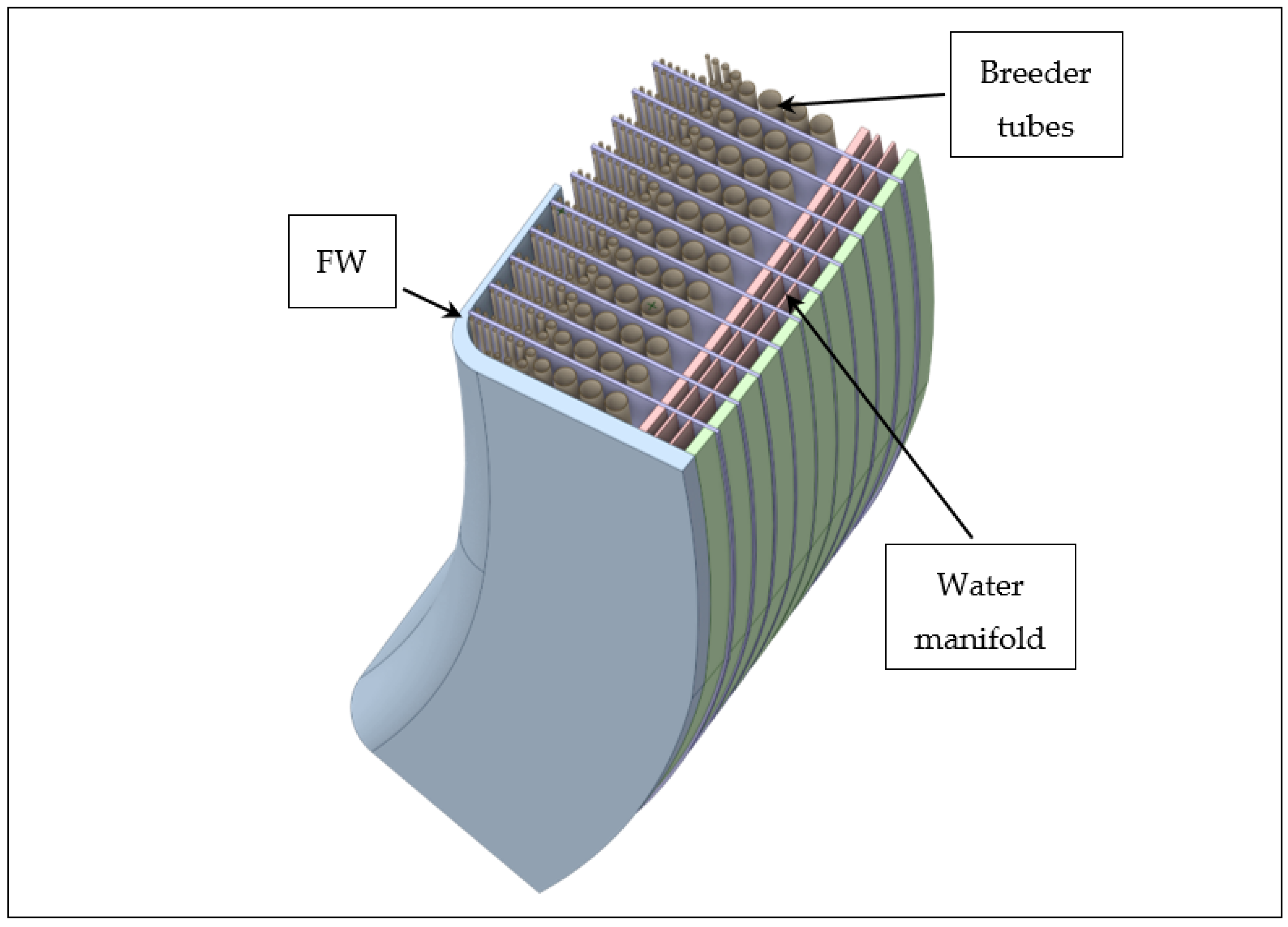
The WLCB blanket casing is formed by the U-shaped FW and the back supporting wall of 50 mm thickness,
Figure 7. The WLCB CAD design shown in
Figure 7 represents a part of the central outboard module. This thickness of the back supporting wall was proven to be sufficient to provide blanket stability. The FW is additionally reinforced to safely ensure the blanket integrity against LOCA: the plasma-faced FW part is 25 mm thick, and the side parts of the FW are 70 mm thick. The 180 mm thick water manifold includes a 30 mm back wall of the BZ and three feeding water channels separated by the steel walls. The BZ is formed with repeating vertical chambers separated by 13 mm thick steel cooling plates. The toroidal thickness of each chamber is 110 mm. The breeder ceramic (Li
4SiO
4 + 35% mol. Li
2TiO
3) as pebbles (64% vol. fraction) is placed in vertical tubes passing in a poloidal direction parallel to the FW arranged in a complex structure as it is shown in
Figure 6. These tubes have different radii varying from 6 mm (plus 1 mm thick wall) to 36 mm (plus 1.5 mm thick wall). The space around tubes is filled with molten Pb. The
6Li enrichment in the breeder ceramic is set to 90% as it is adopted in all breeder blanket designs based on the PbLi liquid metal technology. The first wall contains water (155 bar) cooling channels similar to the WLCB design with six channels per 135 mm vertical height (
Figure 3). The 7 mm thick cooling plates in the BZ have water-cooling channels. The shape and dimensions of these channels are not yet fixed, and they should be defined in a parametric study. As an initial option, a 50% steel/50% water mixture was used in the model. The inlet water temperature is assumed to be ~290 °C, and the outlet one is ~320 °C. All structural elements in the WLCB blanket are made of Eurofer steel.
3.2. MCNP Geometry Models of the WLCB Blankets
The MCNP geometry models for the WLCB blankets were elaborated using a hybrid modeling technology. This assumes both the development of the model on the CAD and MCNP platforms. Such an approach makes the MCNP model generation very flexible that enables quick changes and adjustments of the models to optimize the layout. To this end, the model of the blanket casing, including the FW, the manifolds, and the BZ volume, was developed with CAD software (CATIA v.5) similar to the WCLL-db blanket model preparation. The breeder zone in this model is just filled with a Pb neutron multiplier. The detailed BZ structure was modeled with MCNP geometry development tools; namely, the repeated structure feature was used to reproduce repeated chambers in the WLCB blanket layout. Respectively, an independent, standing-alone MCNP model was elaborated to represent only one chamber with the cooling plates and the poloidal tubes containing breeder ceramic. The tubes were modeled in the original CAD design,
Figure 7, with spline surfaces that exclude direct takeover of the dimensions into the MCNP geometry. To solve this problem, the “broken tube” composed of cylinders is adopted to fit every original one; the poloidal segmentation of the breeder blanket volume and the tubes are shown in
Figure 8. Such geometry artifacts are considered as a kind of a tradeoff adopted for the modeling of the complex geometry that allows generating quite adequate breeder blanket layouts closely reflecting the original design. The MCNP geometry model developed in this way has a big advantage compared to the one for the WCLL-db blanket because it makes possible a rapid creation of numerous geometry modifications for various analyses. The horizontal cuts of the WLCB MCNP geometry model in the mid-plane of the reactor are shown in
Figure 9.
3.3. Results of the Neutronic Simulations for the WLCB DEMO
The MCNP calculations were carried out for the WLCB DEMO in the same way as for the WCLL-db one. Because the WLCB blanket project development is at an early beginning step, the first nuclear response required for the design maturity assessment is its tritium breeding performance, TBR. For the initial blanket configuration,
Figure 9, the very low TBR was calculated, TBR = 1.05. To find the direction for further geometry modifications, the size of the smallest tubes with the breeder ceramic in the front part of the breeder zone was increased from R = 6 mm to R = 16 mm,
Figure 10. For this modification, the tritium breeding performance of the WLCB blanket is still low compared to the TBR
req, TBR = 1.08. The arrangement of the additional poloidal breeder tubes in the rear part of the breeder zone does not contribute noticeably to the TBR.
The insufficient tritium breeding capability of the WLCB blanket can be improved within the optimization procedure used to achieve a reasonable TBR value. The variation technique can be applied not only to the geometry dimensions but also to the general layout of the breeder zone, assuming either the poloidal or radial arrangement of the breeder-containing cells. The former one is suitable for the vertical Pb flow stimulated by gravitational force, and the latter one provides similar irradiation conditions for the breeder ceramic enclosed in the cells from the same toroidal row. Presented in
Table 3 are the horizontal and, when necessary, vertical cuts of the outboard blanket for different BZ layouts: two WLCB geometry layouts with poloidal, two ones with radial arrangements of the breeder tubes, and the one case with the breeder ceramic enclosed in the vertical plates. In all cases, pressurized water with 155 bar is used for the FW and breeder zone cooling. Case #1 assumes three rows of the small poloidal tubes (Ø18 mm) in the front region of the BZ and 11 rows of the bigger tubes (Ø26 mm) in the rear part of the BZ. A 3 cm thick stiffening plate behind the breeder tubes separates the BZ into two parts, and it ensures the integrity of the blanket. The rear part of the BZ behind the separating stiffening plate is filled with a 2 cm neutron graphite layer and massive breeder ceramic blocks. This structure is placed between two vertical cooling plates of 7 mm thickness (50% water/50% steel), and it is repeated in the toroidal direction with the 123 mm step. The vertical disposition of the breeder tubes is also adopted in case #2,
Table 3. For the same dimensions as the BZ unit, the breeder tubes have two annular regions: inner (Ø40 mm, 1 mm steel wall) with water coolant and outer (Ø83 mm, 1.5 mm steel wall) with breeder ceramic. The cooling plate is similar to case #1. In the rear part of the BZ (35 cm), liquid lead is replaced with graphite filler. The tritium breeding capability of the WLCB in the #1 and #2 cases TBR
90 = 1.12 and 1.11, respectively. An index of 90 in the TBR
90 indicates 90% enrichment of
6Li in the breeder ceramic.
The radial integration of the breeder pins in the BZ is presented in cases #3 and #4,
Table 3. For these variants, both radial and vertical cuts of the OB blanket are shown in the table. The BZ units have the same toroidal size, 123 mm, similar to cases #1 and #2. The breeder pins are arranged in horizontal rows with a pitch of 31 and 38 mm in cases #3 and #4, respectively. The pins have the central He purge gas channel (Ø4 mm in case #3 and Ø8 mm in case #4) and the annular breeder ceramic layer (Ø26 mm in case #3 and Ø38 mm in case #4). The 7 mm thick steel/water stiffening plate protects a toroidal deformation of the FW. The tritium generation capability of the WLCB blanket is TBR
90 = 1.11 and 1.12, respectively, in cases #3 and #4. The radial pins arrangement in the WLCB blanket requires an additional strengthening of the whole structure to prevent its destruction due to the hydrostatic pressure of the liquid lead. This issue is out of the scope of this study.
The vertical arrangement of the breeder containing cells in the blanket is more preferably due to the natural liquid lead flow from the upper chimney to the collector at the bottom of the blanket. Case #5 follows the same strategy, similar to cases #1 and #2, but it assumes the arrangement of the ceramic breeder in vertical plates (beds) with the cooling plates attached to them, forming repeated toroidal units. In this case, the toroidal distance between repeated plates is 130 mm, the thickness of the breeder ceramic bed is 30 mm, and the 6 mm thick cooling plates were considered to have a 4 mm water channel with 1 mm thick steel walls. The layout for case #5 was found within the framework of the geometry optimization efforts, and it provides TBR90 = 1.13. No liquid lead circulation in the toroidal direction (between units) is assumed in case #5.
The data on nuclear power densities in the blanket materials required for the stress and thermal-hydraulic analyses are shown in
Figure 11. The results correspond to case #4 (
Table 3). The water manifold effectively moderates and reflects neutrons which lead to the rise of the nuclear power densities there.
As mentioned above, the WLCB blanket could be theoretically operated with and without the circulation of the lead in the outer circuit. The second option requires more justifications addressing the safety issues of the blanket. A generation of various gases in the liquid lead inherently accompanies blanket operation, and in the second mode, it could require the inclusion of additional gas evacuation and control systems to ensure the blanket integrity, prevent any gas leakage into surrounding space, and avoid gaseous diffusion into the steel structures. An inherent accumulation of various light gases such as hydrogen, deuterium, tritium, and helium is expected in the liquid lead due to neutron irradiation. The data presented in
Table 4 provides information for the generation of hydrogen isotopes (H,
2H,
3H) and helium in the WLCB blanket (case #4) during 1 FPY (Full Power Year) without the lead circulation in the outer circuit. The generation of helium in the WLCB blankets is not significant, and it should not be a complex engineering issue in the project. Accumulation of hydrogen with a small admixture of deuterium and tritium should be controlled: it can be dissolved in the lead and taken away into the external loop (in case of circulation), or it can be accumulated in the blanket causing stagnation zones (in case of no circulation). The presence of tritium dissolved in the liquid lead could result in its permeation into the water-cooling system of the blanket.
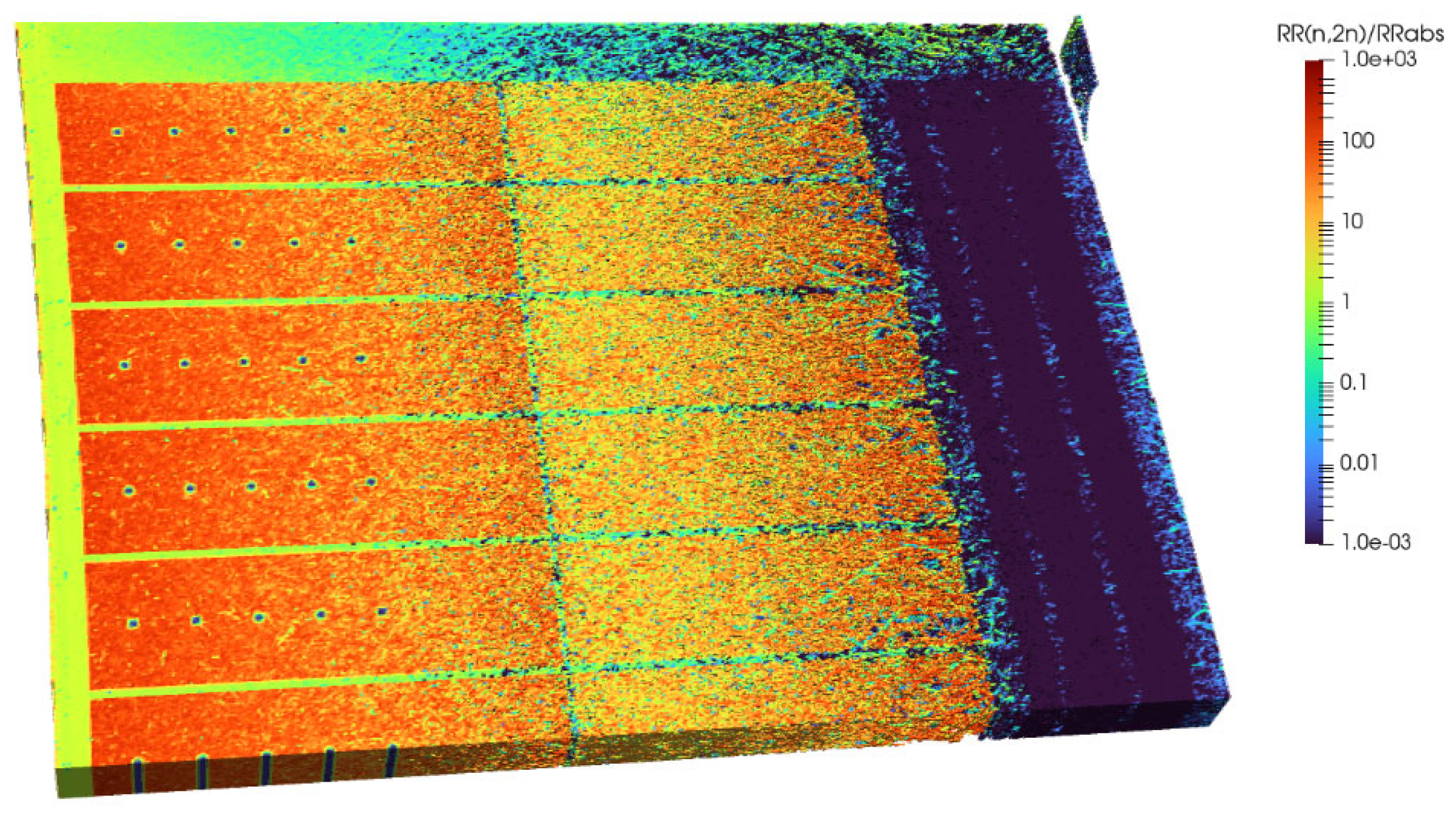
The efficient tritium generation in the breeder ceramic is affected by the neutron multiplication processes in the liquid lead. The relevant for the neutron balance there is an (n,2n) and the neutron absorption nuclear reactions, and the relation between them defines the neutron multiplication. Shown in
Figure 12 is the spatial distribution of the ratio between (n,2n) and neutron absorption reaction rates in the blanket materials, RR
(n,2n)/RR
abs, calculated in the horizontal layer of the central OB blanket between two radial pins in the reactor midplane. The most efficient part of the neutron multiplication in the breeder zone is the volume close to the first wall, and the rear part of the BZ contributes a little to the neutron multiplication process.
3.4. Enhancement of the Tritium Breeding Capability in the WLCB Blanket
The data presented in
Table 3 were obtained due to the comprehensive optimizations of the WLCB blanket geometry layout. The insufficient tritium breeding performance of the blanket, TBR
90 < TBR
req in all cases, indicates a deficiency of the blanket physics: the not sufficient neutron multiplication and the excessive neutron absorption in the blanket materials. No geometry modifications made resulted in the TBR exceeding 1.13. The next level of the WLCB design optimization used to increase the TBR is the choice of alternative materials.
The most evident modifications were adopted to the breeder ceramic. To this end, the
6Li enrichment was increased up to 98%. The gain in the TBR was found in all cases ΔTBR = 0.01, and therefore TBR
98 does not exceed 1.14 in all cases. Another theoretical opportunity to enhance the TBR is the increase of the packing factor of the breeder ceramic pebbles. The simulation performed to study this effect showed almost no effect on the TBR gain, while the packing factor increased from 64% to 80%. The same effect was reported for the HCPB DEMO blankets [
17], where TBR achieved the maximum with the packing factor around ~64%. The tritium generation increases in the small radial layer in the front region of the BZ with the increase of the packing factor of the breeder ceramic, and the rear part of the BZ contributes respectively significantly less to the total result. The next modification applied to the breeder ceramic was the choice of another, more efficient material providing higher tritium release under neutron irradiation compared to the standard lithium ortho-silicate. An octa-lithium plumbate Li
8PbO
6 (melting point > 800 °C) and Li
8ZrO
6 (melting point 1336 °C) [
17,
22,
23] were chosen as the most advanced breeder ceramics to substitute the Li
4SiO
4 in the whole breeder zone. With the
6Li enrichment of 98% in lithium, the tritium breeding in the WLCB increased significantly up to TBR
adv = 1.18 (see the results for this option in
Table 3) and up to TBR
adv = 1.17 (case #5, not presented in
Table 3) with Li
8PbO
6 and Li
8ZrO
6 breeder ceramics respectively. Despite the very promising results, the technology of these ceramics must be well-established, validated, and certified for practical use in the DEMO project.
The significant neutron absorption in the BZ of the WLCB blanket could be noticeably suppressed in the case of heavy water use for blanket cooling. The change of the coolant substance is a substantial alteration of the WLCB blanket layout that requires additional studies to prove its feasibility in the DEMO project. The appropriate modifications were implemented to account for the heavy water cooling: the descriptions of the FW, cooling plates, and cooling tubes were modified in the MCNP geometry model accordingly. The gain of the tritium generation was found to be significant: ΔTBR
D2O = 0.02 relative to the TBR
98 in all cases of the WLCB geometry layouts shown in
Table 3. Thus, TBR = TBR
98 + ΔTBR
D2O = 1.16 (case #5,
Table 3) could be achieved by switching to the heavy water coolant. The crucial disadvantage of this coolant is the parasitic tritium generation due to the
2H(n,γ)
3H nuclear reaction. The accumulation of tritium in the heavy water coolant of the WLCB blanket within the 1 FPY was assessed for case #3 (as an example) and presented in
Table 5. Assuming that the different coolant flows specified in
Table 5 will be mixed together in the outlet channels of the blankets, the average specific tritium generation during the reactor full power year could achieve ~7.5 × 10
8 Bq/kg. This specific activity appeared to be lower compared to the one accumulated in the CANDU reactors [
24,
25]. Nevertheless, any additional parasitic tritium generation in the DEMO coolant leads to additional environmental risks and potential problems with the reactor licensing. Additionally, this approach to enhance the blanket’s tritium breeding performance could drastically increase the capital and operational costs and likely prevent a DEMO public acceptance.
4. Discussion
Starting from the CATIA models of the WCLL and WLCB outboard blankets, the CAD models of the 11.25° DEMO toroidal segment suitable for the neutronic simulations were elaborated for both blanket concepts. The models are well-detailed, and they include all essential geometry cells to represent the original blanket design.
The models are built on a modular basis that enables replacing the different parts without destroying the whole structure. The DEMO generic model serves as the basis for the integration of all separate CAD models representing the blanket design (FW, manifolds, BZ). These separate CAD models were converted into the MCNP geometry representation and included in the DEMO MCNP generic model using the modular hierarchy. The main nuclear responses were calculated using the MCNP-6.2 code and the JEFF-3.3 nuclear data.
The new design of the WCLL blanket, WCLL-db, provides better use of the blanket space for tritium breeding and the achieved TBR = 1.16 is sufficient to enable the sustainable tritium fuel cycle. There is the potential to increase the TBR with optimized FW (water content). A steel content in the breeder zone is a crucial factor for the TBR. Further reinforcement of the blanket structure will result in significant losses of the TBR. The temperature effects in the blanket materials should be accounted for in the TBR assessment.
The use of the PbBi eutectic in the WCLL-db blanket has potential environmental risk due to the accumulation of 210Po. The activation analyses performed to assess the amount of the 210Po production in the WCLL-db DEMO reveals the significant total mass of this isotope in the reactor that could reach ~500 g during the first phase of the DEMO operation. Considering the very low occupational limits for the DEMO personnel, this could be a potential show-stopper for the use of PbBi and as well for the WCLL-db in the DEMO. As the solution to this safety problem, the replacement of the PiBi with other Pb-based compounds was proposed. The use of such compounds could provide the same tritium breeding performances of the WCLL-db blanket similar to the one obtained with the initial design.
The geometry modeling and the particle transport calculations for the WLCB breeder blanket concept were performed utilizing the hybrid procedure leading to the very flexible blanket layout. The combination of the modular structure of the geometry model and the repeated structure feature of the MCNP allows the comprehensive optimization simulations to outline and establish the most efficient blanket layout. Several geometry configurations of the WLCB blanket breeder zone were studied and found to be potentially capable of providing reasonable tritium breeding performance with the arrangement of the breeder ceramic: (a) in the poloidal tubes, (b) in the radial breeder pins, and (c) in the vertical beds. In all investigated variants with standard 90% 6Li enrichment, TBR does not exceed TBR90 ≤ 1.13, and therefore, it is below the required value TBR90 < TBRreq. In the case of the 98% 6Li enrichment in the breeder ceramic, the gain of the TBR is ΔTBR = +0.01, which does not significantly improve tritium breeding capability.
The modifications applied to the blanket layout provided for the WLCB blanket the TBR98 ≤ 1.14. Another way to increase the TBR is the utilization of advanced materials in the breeder zone. The following two options were studied: the alternative breeder ceramic composition with the higher Li content and the use of heavy water as the coolant. Within the former choice, two breeder ceramics for the WLCB blanket were investigated: Li8PbO6 and Li8ZrO6. Both have a high Li content in the mixture, but the first one is stable below 800 °C, and the second one has a melting point above 1300 °C. By making use of these compounds, the tritium breeding capability of the WLCB blanket can be increased by up to 3%, and therefore the TBRadv ≥ TBRreq can be achieved. The relatively low melting point in the case of the Li8PbO6 ceramic should not be a big technological issue because water can provide more efficient cooling compared to the HCPB conditions with the helium coolant. Before the implementation of this option, the technical aspects of the pebbles production from these ceramics on the industrial scale should be investigated, and the appropriate technology should be established, as well as their characterization, long-term stability at high temperatures and behavior under irradiation (especially with respect to tritium dynamics).
The heavy water coolant in nuclear technology is well studied, and it is in routine usage in the CANDU types of nuclear reactors. Therefore, its application in fusion technology might be quite feasible. Due to the significantly low parasitic neutron absorption, the TBR gain in the WLCB blanket could reach δTBR ≈ 2%. The essential drawback of the heavy water coolant is the inherent tritium accumulation due to the neutron irradiation and hence, certain risk for the facility because of the possible lithium leakage in the pipelines and additional gamma irradiation to the environment. The simulations done to study this option applied to the DEMO reactor confirmed tritium production in the WLCB DEMO but the amount of the accumulated tritium is less compared to the conventional heavy water reactors. This fact, nevertheless, does not imply a priori this option is potentially feasible in fusion technology. The safety issues associated with heavy water coolant usage in the DEMO blanket have to be examined first. Both options for the tritium generation enhancement being applied separately or together could result in the promising WLCB breeder blanket layout.
5. Conclusions
Within the framework of the EUROfusion breeder blanket R&D activity, numerical simulations were performed to provide the principal nuclear responses requested for the blanket design work. The main efforts are concentrated on (1) the increase of the breeder blanket functionality and (2) the search for hybrid solutions combining the advantages of the currently developed WCLL and HCPB concepts. To this end, very detailed geometry models of the WCLL-db and WLCB breeder blankets were developed and integrated into the DEMO generic model to perform high-fidelity neutronic simulations and to provide the nuclear responses addressing the blanket design needs.
The most basic system response, TBR, was assessed to demonstrate the tritium breeding capabilities of the new blankets and to demonstrate the prospects of the sustainable tritium fuel cycle. The newly elaborated WCLL-db breeder blanket layout enables more rational usage of the blanket space and demonstrates high enough tritium breeding performance to provide a sustainable tritium supply for the reactor needs. The continuation of the design activity, i.e., a comprehensive study of different technological, safety, and economic aspects, could lead to the integration of the WCLL-db breeder blanket in the EUROfusion project. The WLCB breeder blanket development is in the early phase, where the most basic parameters have to be defined first as a prerequisite. The tritium breeding capabilities of this concept are moderate, and TBR does not exceed TBRreq unless serious appropriate solutions addressing changes in the materials used are implemented. If the technological and safety issues associated with the alternative materials in this concept are clarified and solved, the tritium breeding performance of the WLCB blanket could be significantly improved to match the system requirements.
Author Contributions
Conceptualization, P.P., F.A.H. and I.M.; Methodology, P.P., I.M. and J.H.P.; Software, P.P. and J.H.P.; Validation, P.P. and J.H.P.; Formal analysis, P.P.; Investigation, P.P.; Resources, F.A.H.; Data curation, P.P. and F.A.H.; Writing—review & editing, P.P. and F.A.H.; Visualization, P.P. and J.H.P.; Project administration, F.A.H. and I.M.; Funding acquisition, F.A.H. and I.M. All authors have read and agreed to the published version of the manuscript.
Funding
This research received no external funding.
Institutional Review Board Statement
Not applicable.
Informed Consent Statement
Not applicable.
Data Availability Statement
Data is unavailable due to privacy restrictions.
Acknowledgments
This work has been carried out within the framework of the EUROfusion Consortium, funded by the European Union via the Euratom Research and Training Programme (Grant Agreement No 101052200—EUROfusion). Views and opinions expressed are, however, those of the author(s) only and do not necessarily reflect those of the European Union or the European Commission. Neither the European Union nor the European Commission can be held responsible for them. We also acknowledge support from the KIT-Publication Fund of the Karlsruhe Institute of Technology.
Conflicts of Interest
The authors declare no conflict of interest.
References
- Federici, G.; Boccaccini, L.; Cismondi, F.; Gasparotto, M.; Poitevin, Y.; Ricapito, I. An overview of the EU breeding blanket design strategy as an integral part of the DEMO design effort. Fusion Eng. Des. 2019, 141, 30–42. [Google Scholar] [CrossRef]
- Pereslavtsev, P.; Bachmann, C.; Park, J.H. DEMO tritium breeding performances with different in-vessel components configurations. Fusion Eng. Des. 2021, 166, 112319. [Google Scholar] [CrossRef]
- Arena, P.; Del Nevo, A.; Moro, F.; Noce, S.; Mozzillo, R.; Imbriani, V.; Giannetti, F.; Edemetti, F.; Froio, A.; Savoldi, L.; et al. The DEMO Water-Cooled Lead–Lithium Breeding Blanket: Design Status at the End of the Pre-Conceptual Design Phase. Appl. Sci. 2021, 11, 11592. [Google Scholar] [CrossRef]
- Hernández, F.A.; Pereslavtsev, P.; Zhou, G.; Kang, Q.; D’Amico, S.; Neuberger, H.; Boccaccini, L.V.; Kiss, B.; Nádasi, G.; Maqueda, L.; et al. Consolidated design of the HCPB Breeding Blanket for the pre-Conceptual Design Phase of the EU DEMO and harmonization with the ITER HCPB TBM program. Fusion Eng. Des. 2020, 156, 111614. [Google Scholar] [CrossRef]
- Ilenia, C. Thermal-Structural Investigation of a Breeder Zone Region of the WCLL “Double Bundle”. Available online: http://idm.euro-fusion.org/?uid=2NCWRV (accessed on 20 June 2023).
- Gliss, C.; Ciattaglia, S.; Korn, W.; Moscato, I. Initial layout of DEMO buildings and configuration of the main plant systems. Fusion Eng. Des. 2018, 136 Pt A, 534–539. [Google Scholar] [CrossRef]
- Wu, Y. Multi-functional Neutronics Calculation Methodology and Program for Nuclear Design and Radiation Safety Evaluation. Fusion Sci. Technol. 2018, 74, 321–329. [Google Scholar] [CrossRef]
- Pereslavtsev, P.; Cismondi, F.; Hernandez, F. Analyses of the shielding options for HCPB DEMO blanket. Fusion Eng. Des. 2020, 156, 111605. [Google Scholar] [CrossRef]
- Fischer, U. Material Compositions for PPPT Neutronics and Activation Analyses. Available online: http://idm.euro-fusion.org/?uid=2MM3A6 (accessed on 20 June 2023).
- Werner, C.J.; Bull, J.S.; Solomon, C.J.; Brown, F.B.; McKinney, G.W.; Rising, M.E.; Dixon, D.A.; Martz, R.L.; Hughes, H.G.; Cox, L.J.; et al. MCNP User’s Manual Code, version 6.2; Tech. Rep. LA-UR-17-29981; Los Alamos National Laboratory: Los Alamos, NM, USA, 2017. [Google Scholar]
- Plompen, A.J.; Cabellos, O.; De Saint Jean, C.; Fleming, M.; Algora, A.; Angelone, M.; Archier, P.; Bauge, E.; Bersillon, O.; Blokhin, A.; et al. The joint evaluated fission and fusion nuclear data library, JEFF-3.3. Eur. Phys. J. A 2020, 56, 181. [Google Scholar] [CrossRef]
- Fausser, C.; Puma, A.L.; Gabriel, F.; Villari, R. Tokamak D-T neutron source models for different plasma physics confinement modes. Fusion Eng. Des. 2012, 87, 787–792. [Google Scholar] [CrossRef]
- Moro, F.; Del Nevo, A.; Flammini, D.; Martelli, E.; Mozzillo, R.; Noce, S.; Villari, R. Neutronic analyses in support of the WCLL DEMO design development. Fusion Eng. Des. 2018, 136 Pt B, 1260–1264. [Google Scholar] [CrossRef]
- Pereslavtsev, P.; Hernandez, F.; Zhou, G.; Lu, L.; Wegmann, C.; Fischer, U. Nuclear analyses of solid breeder blanket options for DEMO: Status, challenges and outlook. Fusion Eng. Des. 2019, 146, 563–567. [Google Scholar] [CrossRef] [Green Version]
- Ohno, S.; Kurata, Y.; Miyahara, S.; Katsura, R.; Yoshida, S. Equilibrium Evaporation Behavior of Polonium and Its Homologue Tellurium in Liquid Lead-Bismuth Eutectic. J. Nucl. Sci. Technol. 2006, 43, 1359–1369. [Google Scholar] [CrossRef]
- McFee, R.B.; Leikin, J.B. Death by polonium-210: Lessons learned from the murder of former Soviet spy Alexander Litvinenko. Semin. Diagn. Pathol. 2009, 26, 61–67. [Google Scholar] [CrossRef] [PubMed]
- Hernandez, F.; Pereslavtsev, P. First principles review of options for tritium breederand neutron multiplier materials for breeding blankets in fusion reactors. Fusion Eng. Des. 2018, 137, 243–256. [Google Scholar] [CrossRef]
- Park, J.H.; Pereslavtsev, P. Comparative activation analyses for the HCPB breeding blanket in DEMO. Fusion Eng. Des. 2021, 167, 112338. [Google Scholar] [CrossRef]
- Fleming, M.; Stainer, T.; Gilbert, M. The FISPACT II User Manual; UKAEA-R(18)001; UK Atomic Energy Authority, Culham Science Center: Abingdon, UK, 2018. [Google Scholar]
- Koning, A.J.; Rochman, D.; Sublet, J.C.; Dzysiuk, N.; Fleming, M.; Van der Marck, S. TENDL: Complete Nuclear Data Library for Innovative Nuclear Science and Technology. Nucl. Data Sheets 2019, 155, 1–55. [Google Scholar] [CrossRef]
- Eade, T.; Garcia, M.; Garcia, R.; Ogando, F.; Pereslavtsev, P.; Sanz, J.; Stankuna, G.; Travleev, A. Activation and decay heat analysis of the European DEMO blanket concepts. Fusion Eng. Des. 2017, 124, 1241–1245. [Google Scholar] [CrossRef]
- Hayashi, T.; Konishi, S.; Okuno, K. Tritium release behavior from neutron irradiated Li8PbO6. J. Nucl. Mater. 1990, 170, 60–65. [Google Scholar] [CrossRef]
- Wyers, G.P.; Cordfunke, E.H. Phase relations in the system Li2O-ZrO2. J. Nucl. Mater. 1989, 168, 24–30. [Google Scholar] [CrossRef]
- Park, T.-K.; Kim, S.-K. Tritium: Its generation and pathways to the environment at CANDU 6 generating stations. Nucl. Eng. Des. 1996, 163, 405–411. [Google Scholar] [CrossRef]
- Song, K.M.; Sohn, S.H.; Kang, D.W.; Chung, H.S. Introduction to Wolsong Tritium Removal Facility (WTRF). In Proceedings of the Transactions of the Korean Nuclear Society Autumn Meeting, Busan, Republic of Korea, 27–28 October 2005. [Google Scholar]
| Disclaimer/Publisher’s Note: The statements, opinions and data contained in all publications are solely those of the individual author(s) and contributor(s) and not of MDPI and/or the editor(s). MDPI and/or the editor(s) disclaim responsibility for any injury to people or property resulting from any ideas, methods, instructions or products referred to in the content. |
© 2023 by the authors. Licensee MDPI, Basel, Switzerland. This article is an open access article distributed under the terms and conditions of the Creative Commons Attribution (CC BY) license (https://creativecommons.org/licenses/by/4.0/).


