Article

Research on Mechanism Design and Kinematic Characteristics of Self-Propelled Photovoltaic Cleaning Robot

1
Hebei Provincial Key Laboratory of Heavy Machinery Fluid Power Transmission and Control, Yanshan University, Qinhuangdao 066004, China
2
Key Laboratory of Advanced Forging & Stamping Technology and Science, Yanshan University, Qinhuangdao 066004, China
3
Hebei Key Laboratory of Special Delivery Equipment, Yanshan University, Qinhuangdao 066004, China
*
Author to whom correspondence should be addressed.
Appl. Sci. 2023, 13(12), 6967; https://doi.org/10.3390/app13126967
Submission received: 8 May 2023 / Revised: 28 May 2023 / Accepted: 5 June 2023 / Published: 9 June 2023
(This article belongs to the Special Issue Machine Automation: System Design, Analysis and Control)

Abstract

:
A hydraulic drive-based self-propelled photovoltaic panel cleaning robot was developed to tackle the challenges of harsh environmental conditions, difficult roads, and incomplete cleaning of dust particles on the photovoltaic panel surface in photovoltaic power plants. The robot has the characteristics of the crawler wheel drive, rear-wheel-independent turning and three-point-independent suspension design, which makes it adhere to the walking requirements of complex environmental terrains, more flexible in turning and automatically levelling so that the stability of the boom mechanism during walking can be ensured. The kinematics model of the upper arm structure equipped with the end cleaning device was built, and the optimized Circle chaotic map and nonlinear weight factor were introduced to enhance the search ability and convergence speed of the sparrow algorithm. Furthermore, the boom running track was optimized in combination with the seven-order non-uniform B-spline curve. Through optimization, the running time of the boom was reduced by 18.7%, and the cleaning efficiency of photovoltaic panel surface was increased. The effectiveness of self-propelled photovoltaic panel cleaning robot cleaning and the reliability of time-optimal trajectory planning were confirmed through simulation and experiment.

1. Introduction

Energy lays a solid material foundation for the existence and development of human society while significantly stimulating economic growth. However, with the continuous growth of energy demand in society and the reduction in conventional fossil energy supply, green energy has become the focus of attention. Among a wide variety of green energy sources, solar energy has aroused a significant amount of attention toward its advantages, and its development prospects are also broader. Compared with other green energy types, solar energy has the following advantages: (1) it is universal; (2) the storage capacity of solar energy is large and inexhaustible; (3) it is convenient; (4) it is not restricted by space and geographical location; (5) it is environment-friendly. The technology of photovoltaic power generation using solar energy has been extensively employed in numerous countries, such that it has served as a pillar industry of green energy. However, photovoltaic power stations are generally located in desert and Gobi regions characterized by dry climate, high sandstorms, and low precipitation. Dust particles were deposited on the surface of photovoltaic panels under their gravity or under the effect of wind. The accumulated dust can trigger the following problems: (1) blocking of the photovoltaic panel reduces the area of solar radiation received by the photovoltaic panel, affecting power generation efficiency; (2) the rise in its temperature results in hot spots; (3) the corroded surface of photovoltaic panels poses permanent damage to the panels [1,2,3,4,5,6].
With the increasingly serious accumulation of dust particles on the surface of photovoltaic panels, it has seriously constrained the efficiency of photovoltaic power generation, and the dust particles on the surface of photovoltaic panels should be cleaned. The existing disposal methods for dust particles deposited on the surface of photovoltaic panels are elucidated as follows: (1) manual cleaning method: waste of water resources, high labor intensity of workers, high labor cost, long cleaning cycle time, and uncontrollable cleaning effect; (2) self-cleaning of photovoltaic panels: high cost, inability to adapt to relatively harsh environmental conditions and large-scale applications; (3) track-type cleaning robot: reciprocating cleaning operation is performed relying on the guide rail on the photovoltaic panel; the cost of track laying is up-regulated under the irregular arrangement of the photovoltaic panel group, which cannot meet the needs of field operation; (4) mobile vehicle-mounted photovoltaic cleaning robot: capable of automatically adjusting and cleaning photovoltaic panels at different states, effectively cleaning dirt with different adhesion and performing cross-photovoltaic group operations on power plants in different regions [7,8,9,10,11,12,13]. Moreover, the manual cleaning method cannot satisfy the actual needs due to the harsh environment of the photovoltaic power station and the preciousness of water resources; photovoltaic panel self-cleaning technology and track-type cleaning robots cannot conform to the low-cost and high-efficiency cleaning operations with the rising scale of photovoltaic power stations; the complexity of the road surface of the photovoltaic power station makes the vehicle-mounted photovoltaic cleaning robot unstable in the walking process, resulting in damage to the photovoltaic panel surface by the cleaning device. Based on the above analysis, it is of great significance to develop a novel type of self-propelled photovoltaic panel cleaning robot to efficiently clean the dust particles, snow and dust covers on the photovoltaic surface without water so that it has the characteristics of modular mechanical structure, intelligent control system and automatic walking.

1.1. Structural Design

Regarding structural design, Fan et al. [14] proposed a novel type of anhydrous photovoltaic panel cleaning robot, developed a negative pressure adsorption wheel walking system and a rolling brush negative pressure dust removal system to ensure the stability of the robot’s operation, and verified the effectiveness of its design through experiments. Antonelli et al. [15] investigated an unmanned photovoltaic cleaning robot without a guide rail. The robot walked autonomously in a half-track manner, employing alternating rotating independent spiral brushes to clean the photovoltaic panel surface while using ultrasonic sensors to detect the spatial position of the robot in real time. The reliability of its design was confirmed experimentally. Cai et al. [16] explored the structure of the dust removal port of the photovoltaic panel cleaning robot, theoretically analyzed the gas–solid two-phase flow equation, the correlation between the pressure distribution and the velocity of the dust particles during the dust removal, simulated and analyzed the flow field, and optimized the structural parameters of the dust removal port based on the orthogonal experimental method. Khan et al. [17] proposed an automatic self-cleaning photovoltaic panel device comprising installation structure, cleaning wipes and relevant mechanical components. The pulley mechanism was developed to drive the cleaning wipes to dust the photovoltaic panel and improve the power generation efficiency of the photovoltaic panel. Ölmez et al. [18] developed a novel type of autonomous path planning and anhydrous cleaning robot for photovoltaic panels. After a flexible photovoltaic panel was installed on the robot as a power source, a rubber wheel was adopted to achieve omnidirectional rotation, and the dust particles on the photovoltaic panel surface were integrated and then stored through vacuum suction. With the cross-arm structure of the photovoltaic panel cleaning robot as the research object, Hou et al. [19] adopted topology optimization for the lightweight design of the cross-arm structure based on the power correlation analysis, which increased the safety and practicality of the cross arm. Nguyen et al. [20] investigated the rubber tracked photovoltaic panel cleaning robot while exploring the problem of this type of robot slipping on wet photovoltaic panel surfaces in depth. They built a theoretical model and analyzed it. The accuracy of the theoretical model was verified through experiments. Jang et al. [21] proposed a walking cleaning robot attached to the surface of photovoltaic panels which uses a driving unit composed of three driving lines to clean the photovoltaic panel surface. The reliability of the developed cleaning robot was confirmed experimentally. Parrott et al. [22] developed a novel type of guide rail photovoltaic cleaning device using silicone rubber foam brush to clean the photovoltaic panel surface. On that basis, the damage to the photovoltaic panel surface could be reduced, and the cleaning performance could be enhanced.

1.2. Intelligent Control

Regarding control, Divyavani et al. [23] studied a novel photovoltaic panel cleaning system using FPGA and infrared sensors to identify the cleaning path and verified the effectiveness of the system through experiments. The power generation efficiency of the cleaned photovoltaic panel was increased by 35%. Amin et al. [24] developed an automated monitoring and cleaning system for photovoltaic panel surfaces. The developed system is capable of evaluating the degree of dust accumulation by monitoring the color of the photovoltaic panel surface so that the robot can be driven to clean the dust accumulation area. Al−Jarrah et al. [25] developed a speed control strategy for the photovoltaic panel cleaning robot to increase the corresponding rapidity and stability. It was ensured that the swing arm can move up and down along the photovoltaic panel surface. Morando et al. [26] adopted UAV to inspect and maintain photovoltaic power plants and proposed a strategy of segmentation and visual servo tracking of photovoltaic modules to monitor the dust accumulation on photovoltaic panels and elevate the intelligence level of photovoltaic power plants. Rehman et al. [27] developed a control system for unmanned aerial vehicles (UAVs) to clean photovoltaic panels which employed downward thrust during cruise to remove the dust on the panels. The effectiveness of the system was verified experimentally. Gupta et al. [28] proposed a self-cleaning photovoltaic sliding system which was validated experimentally to increase the efficiency of photovoltaic power generation and protect it from damage from the natural environment.
With the continuous development of photovoltaic panel cleaning technology, the guide rail and panel self-cleaning technology cannot conform to the cleaning needs, and the cost is too high. The novel self-propelled photovoltaic panel cleaning robot will be more extensively employed. Due to the complexity of the road environment of photovoltaic power plants, the design of their vehicle chassis requires suspension and drive systems. The distance limitation of the photovoltaic panel array space enables the vehicle to have a steering system. As the end effector, the cleaning device needs a degree of freedom to control its working attitude. In order to place the cleaning device on the photovoltaic module, at least two degrees of freedom are needed to control at the plane level. In the non-working posture, the cleaning device needs to be retracted, and a rotational degree of freedom is needed to ensure its spatial activity; therefore, the boom mechanism adopts a four-degree-of-freedom series structure.
Based on the requirements of cleaning the dust particles on the photovoltaic panel surface, this study proposes a novel self-propelled photovoltaic panel cleaning robot structure, establishes the kinematics model of the boom system, uses the optimized sparrow algorithm combined with the seventh order non-uniform B-spline curve to optimize the trajectory time of the boom, reduces the trajectory time of the boom, and improves the boom response speed and cleaning efficiency.
Thus, the main contributions of this study can be summarized as follows:
(1)
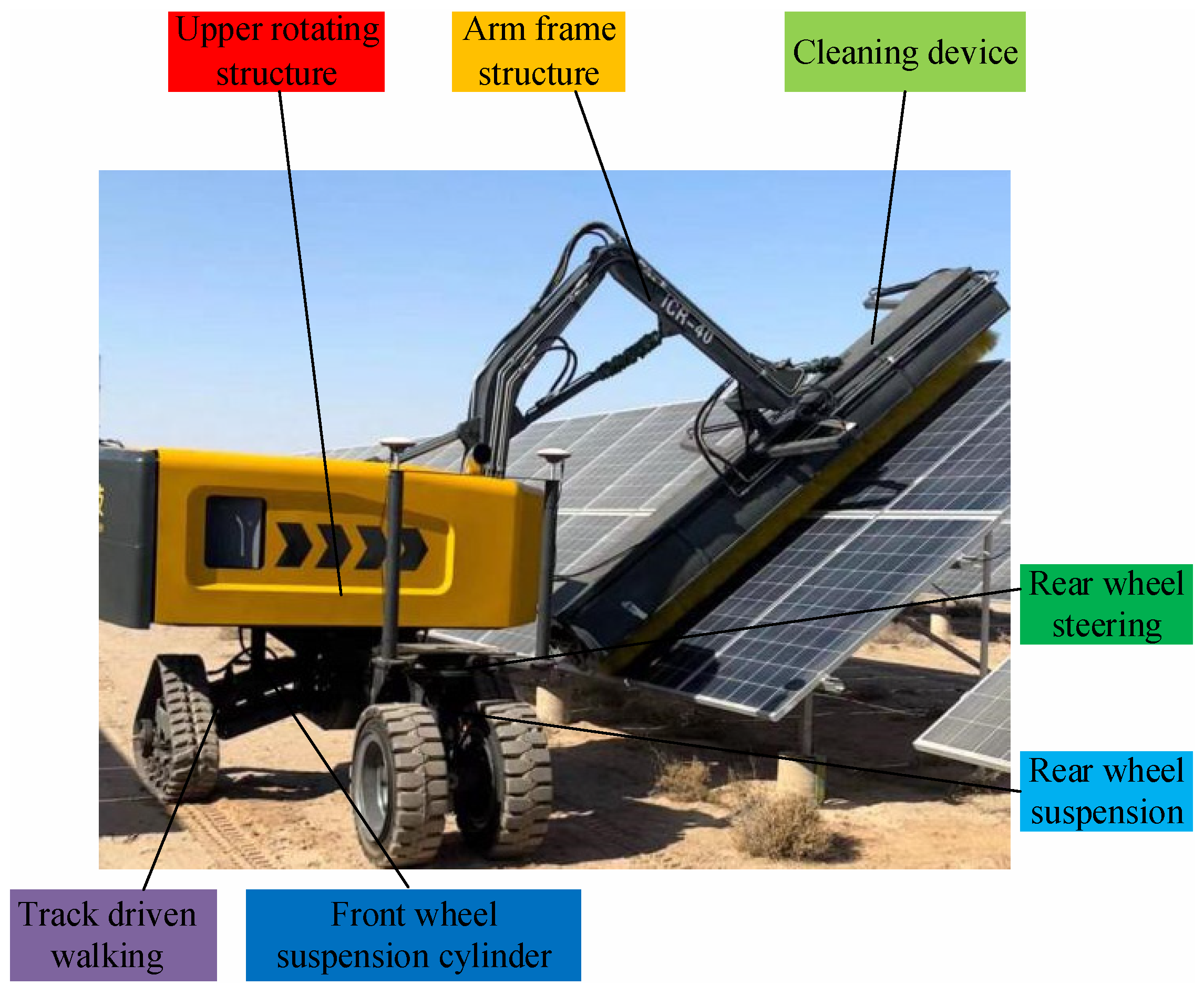
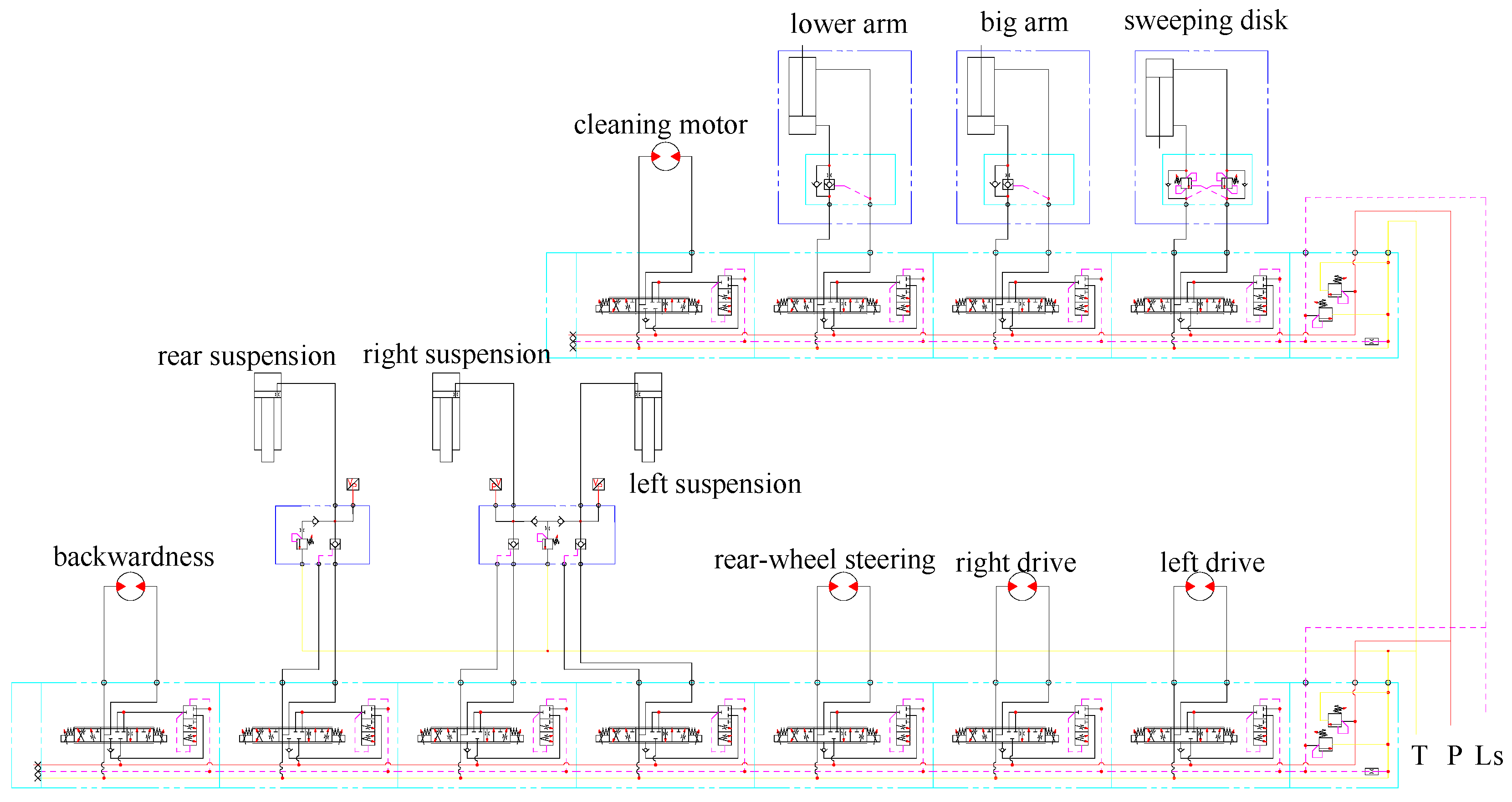
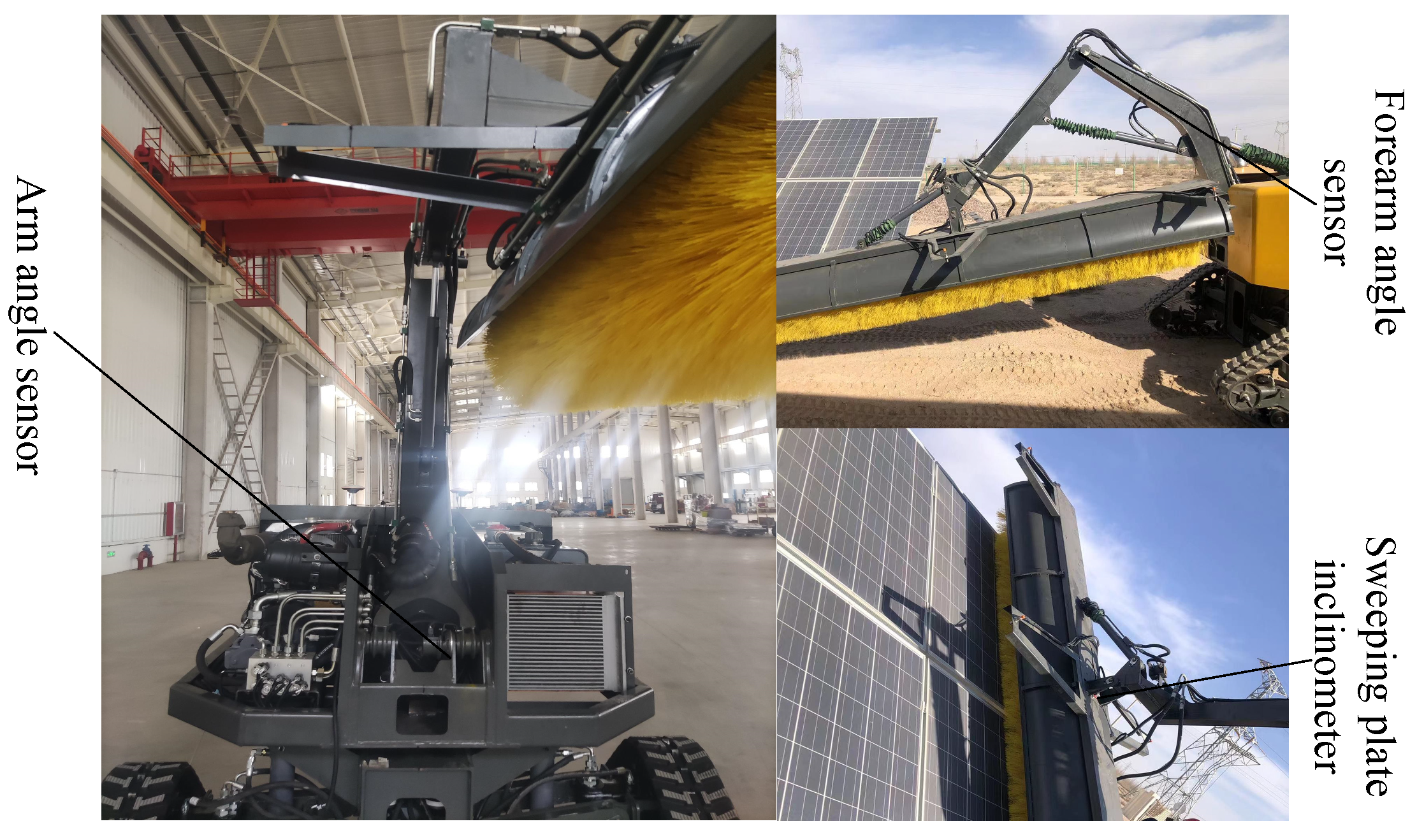
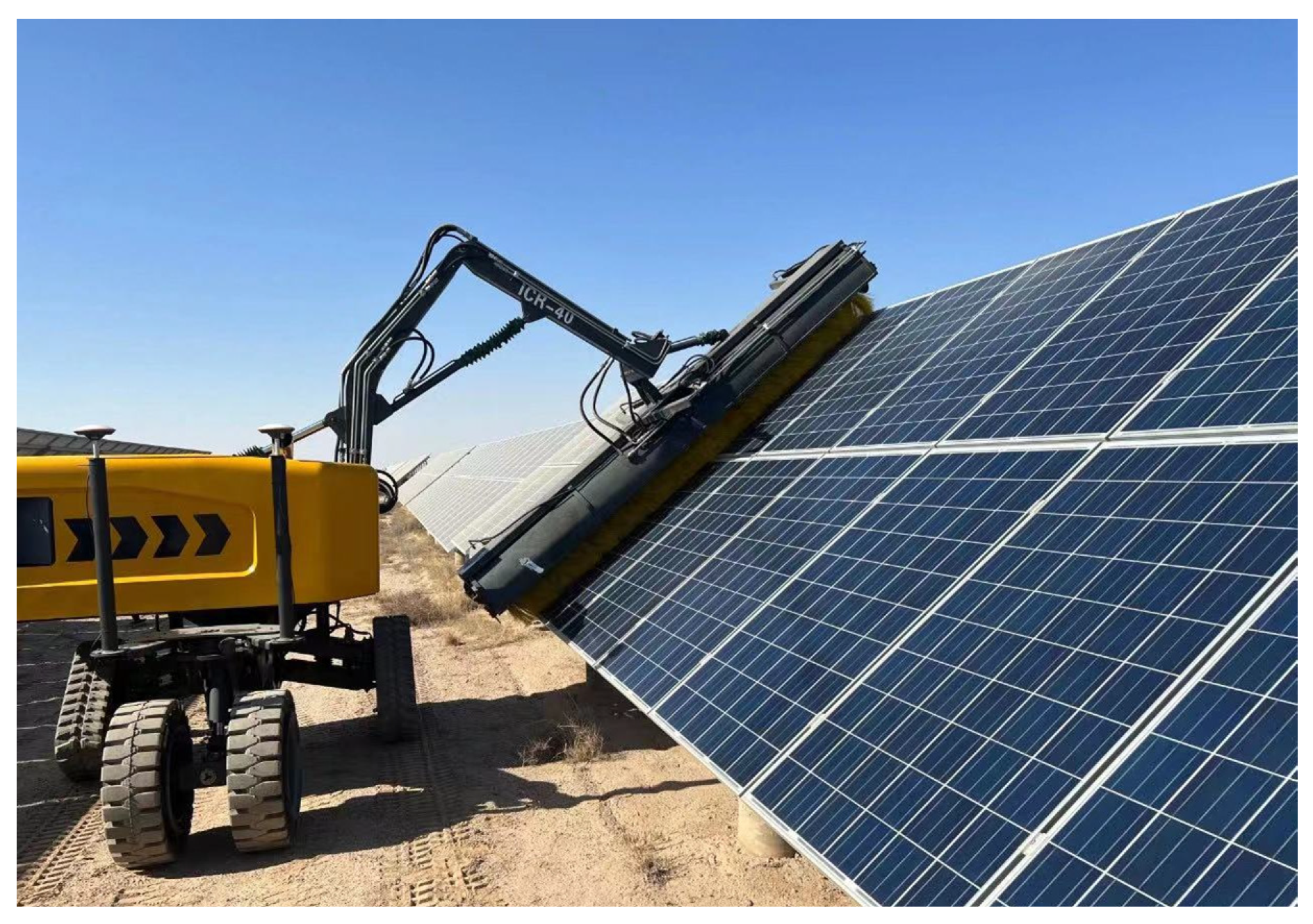
A novel self-propelled hydraulic driven photovoltaic panel cleaning robot was proposed in accordance with the environmental factors for photovoltaic power plants and the arrangement of photovoltaic panels. Tracked wheel drive was adopted to increase the contact surface with the ground and improve road adaptability, capable of completing walking functions under harsh environmental conditions. The three-point independent suspension design enabled the robot to level automatically during walking so that the stability of the upper frame mechanism during walking could be ensured. Independent rear-wheel steering is capable of increasing the turning radius of the robot, thus making its steering more flexible. The design of a three-joint-series arm structure on the vehicle was equipped with an end-cleaning device, and multiple detection components (e.g., angle sensors and inclinometers) were installed to conform to the unmanned and intelligent cleaning requirements for the photovoltaic panel surface.
(2)
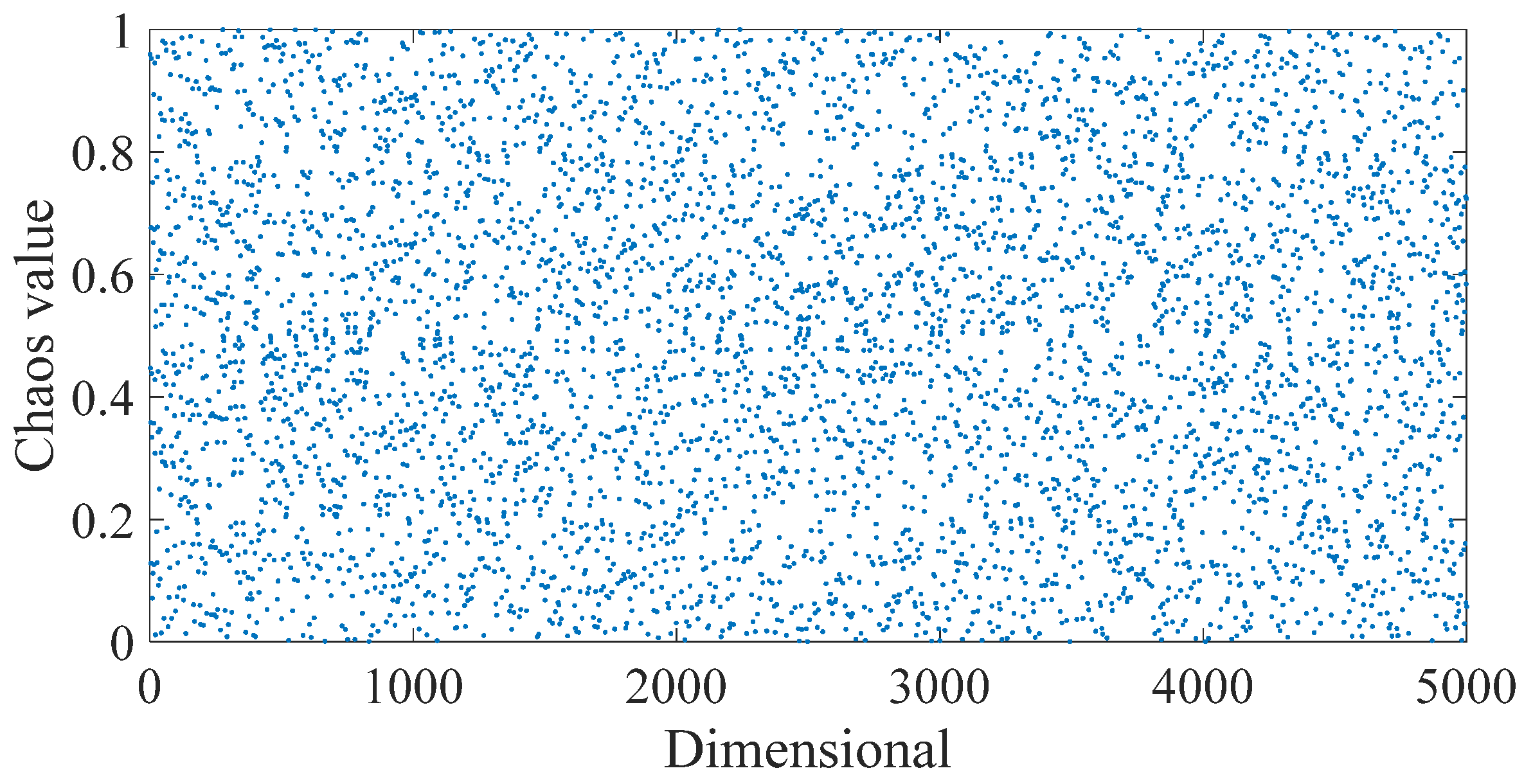
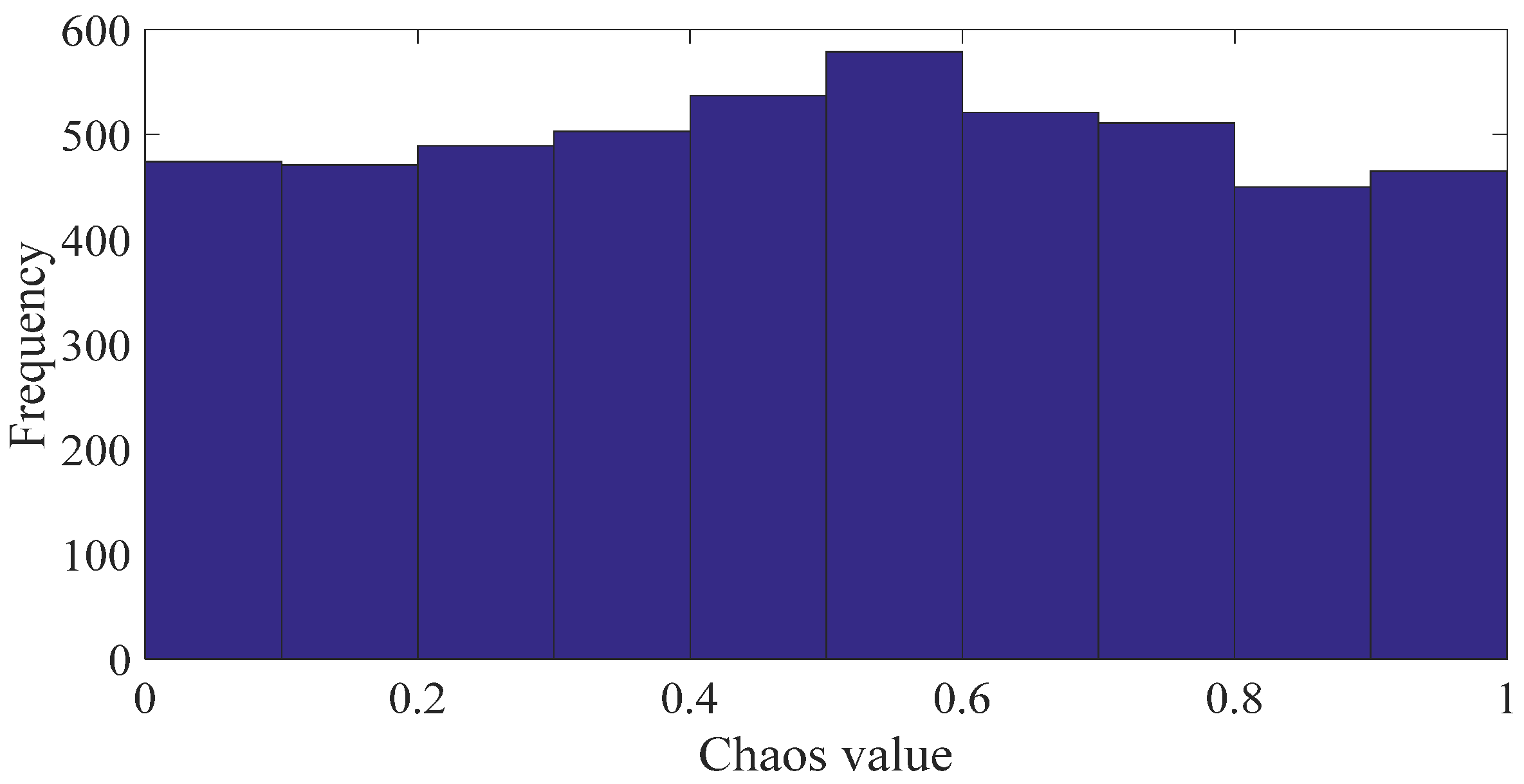
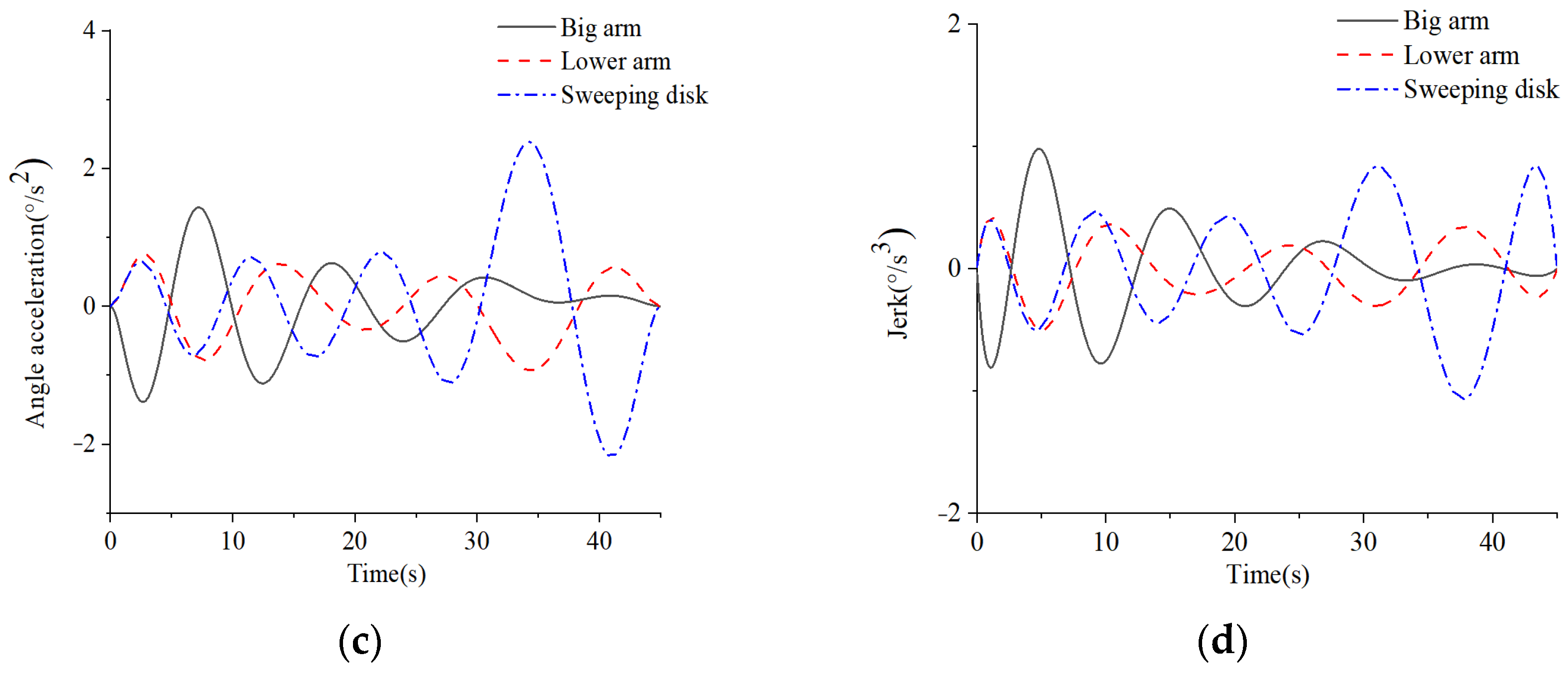
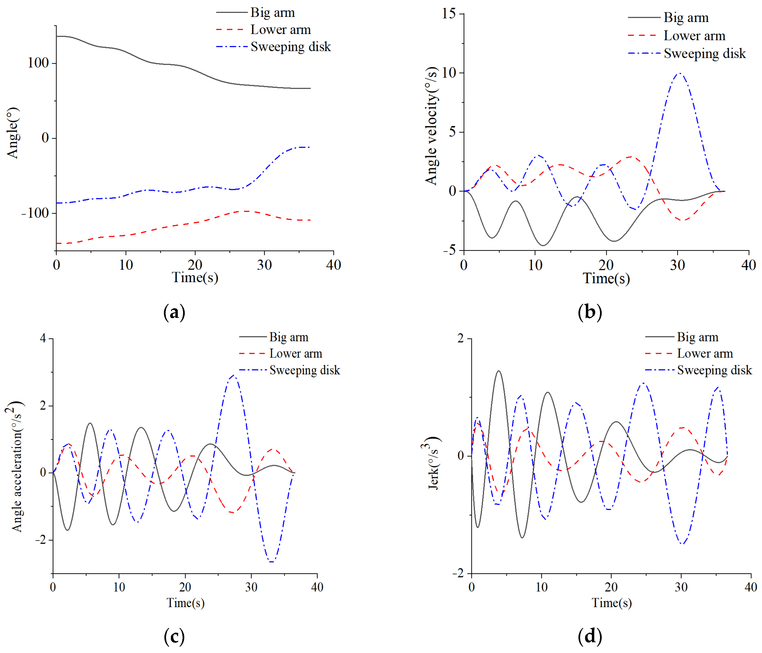
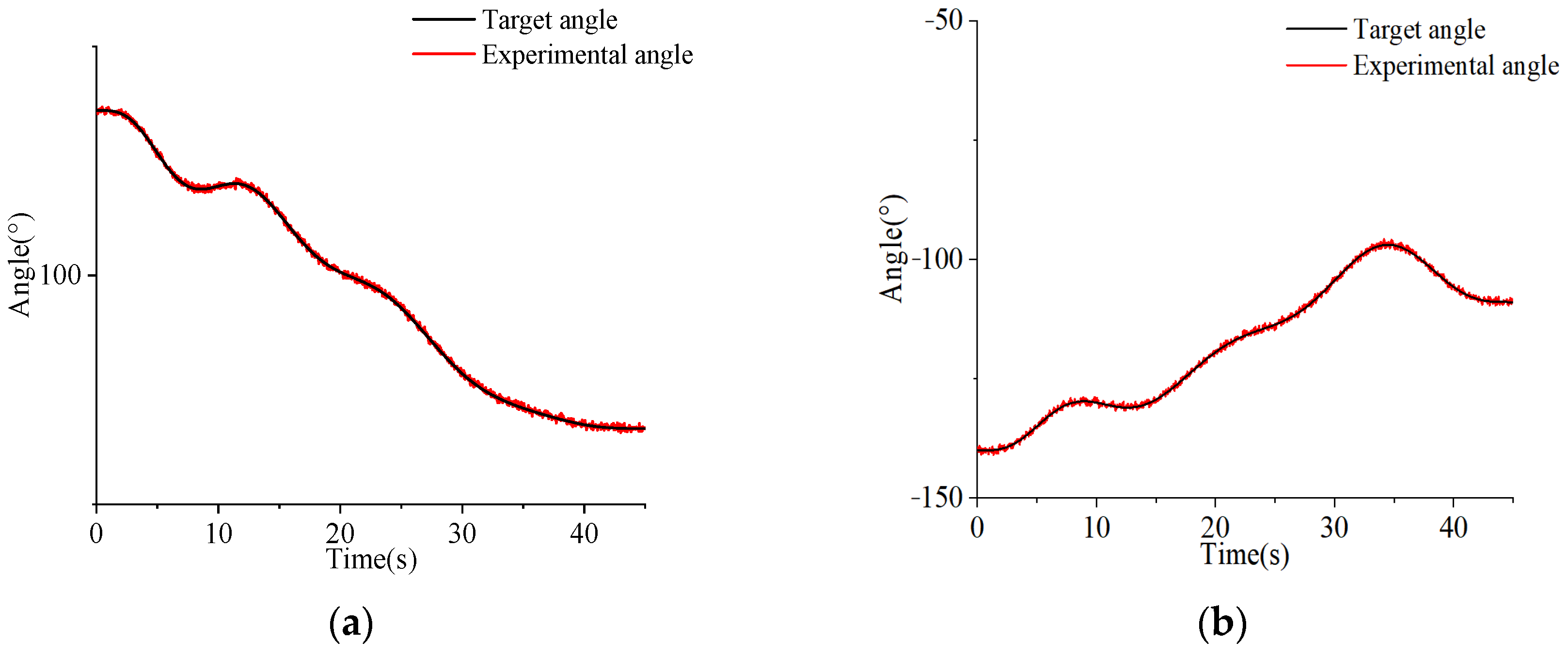
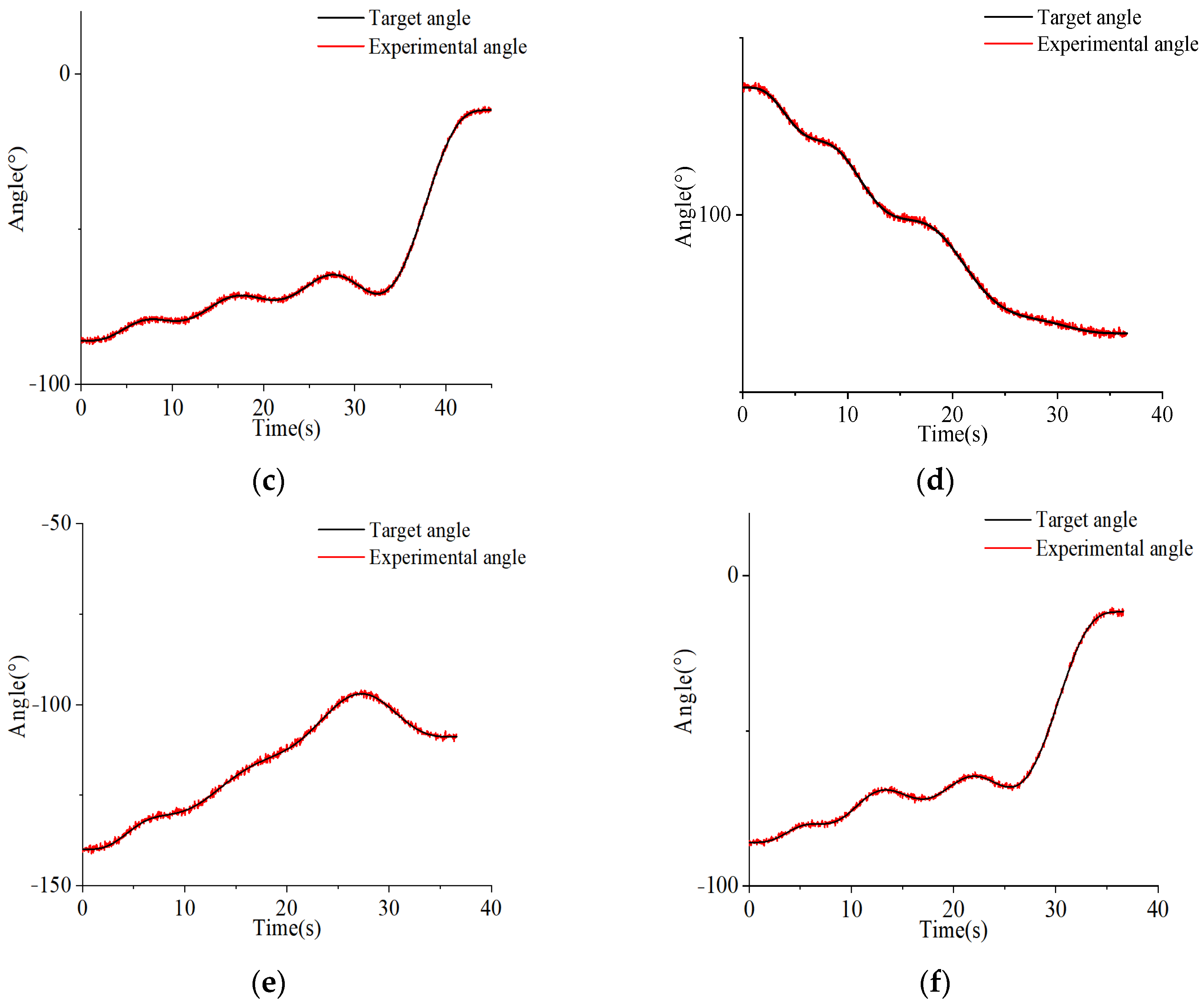
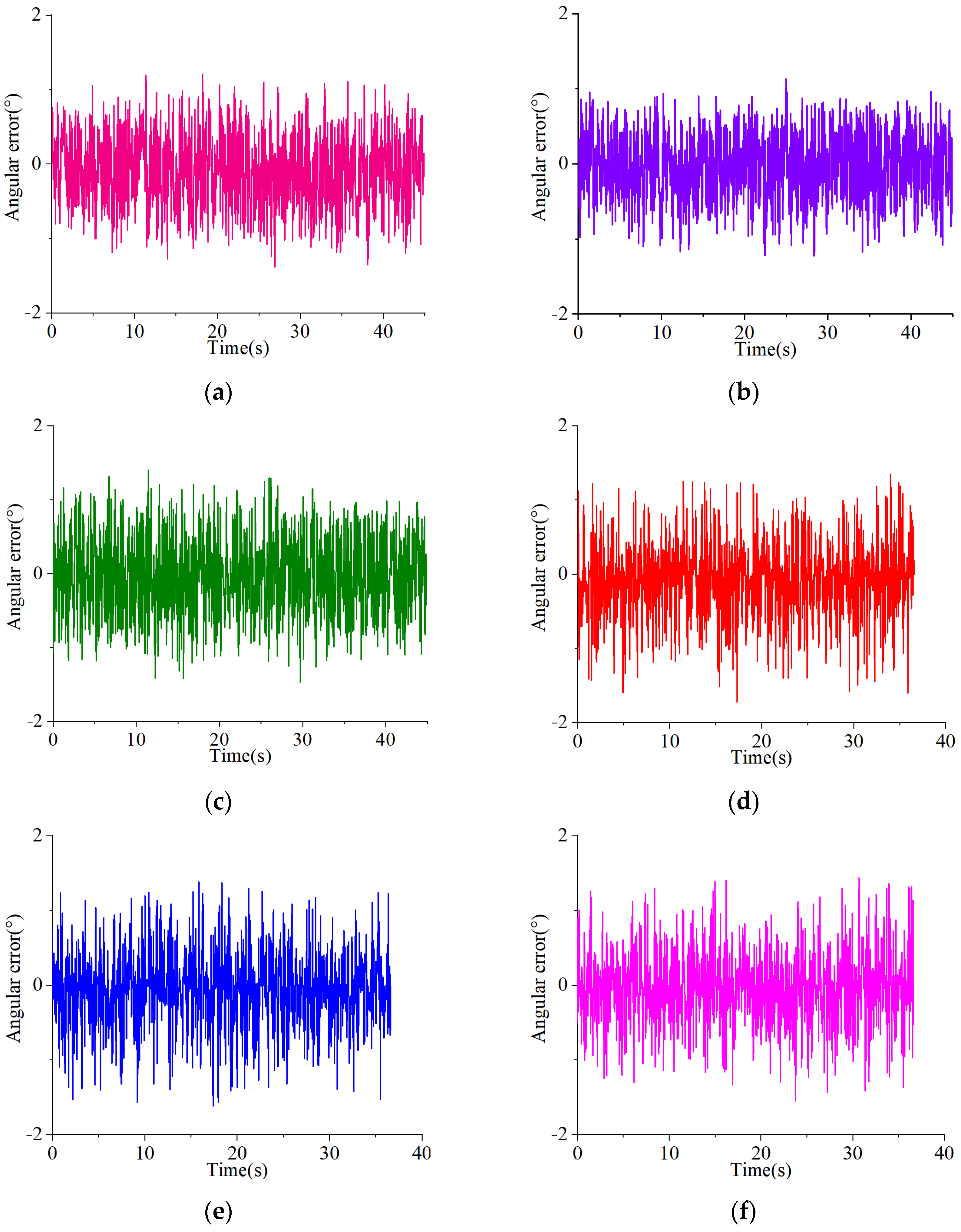
The kinematics model of the boom cleaning device was built, and the optimized Circle chaotic map and nonlinear weight factor were introduced to increase the initial population diversity, search ability and convergence speed of the sparrow algorithm. The optimized sparrow algorithm and non-uniform B-spline curve were employed to optimize the time planning of the boom trajectory, and the speed of cleaning was increased. The reliability of the cleaning effect of the developed photovoltaic panel cleaning robot and the effectiveness of the optimal time were verified through the combination of simulation and experiment.
The rest of this study is organized as follows. In Section 2, the three-dimensional (3D) structure design and characteristics of the novel self-propelled photovoltaic panel cleaning robot are presented. In Section 3, the kinematics model of the boom cleaning system is built. In Section 4, the time-optimal trajectory planning of the seven-order non-uniform B-spline curve combined with the optimized sparrow algorithm is proposed. In Section 5, the effectiveness of the developed robot cleaning the photovoltaic panel surface and the reliability of the time-optimal planning are verified through experimental research and then summarized in Section 6.

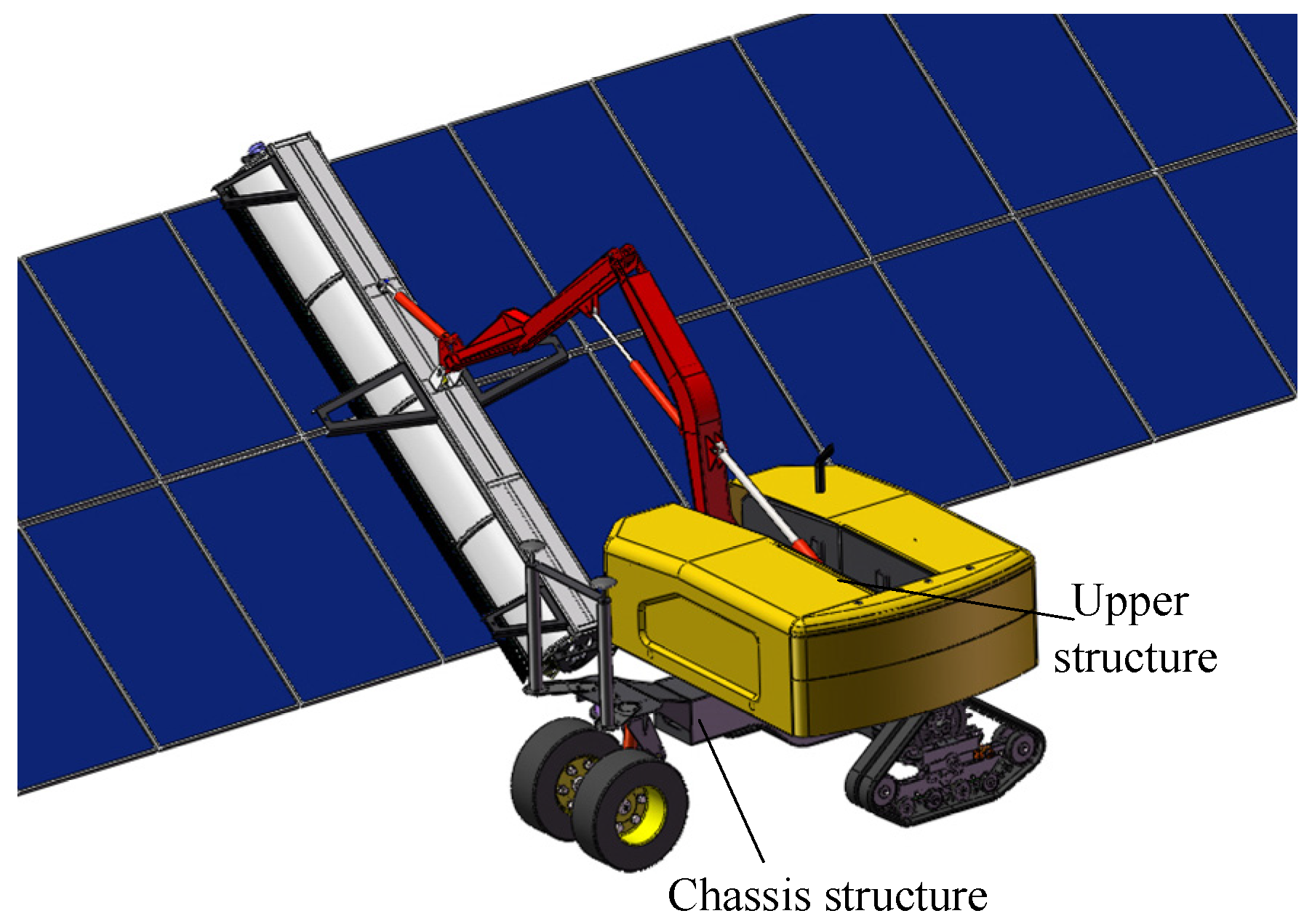
2. Structural Design of Photovoltaic Panel Cleaning Robot

A novel type of self-propelled photovoltaic panel cleaning robot structure was proposed in accordance with the height and arrangement of photovoltaic panels in photovoltaic power stations and the complexity of the road surface. In general, the composition of the robot comprised chassis structure and upper structure, which were connected to each other through rotary drive components. The design of the chassis structure primarily aimed to adapt to complex road environments, maintain the chassis level during the operation of the vehicle, and avoid the jitter phenomenon of the arm frame structure when cleaning the photovoltaic panel surface. The design of the boarding mechanism was constructed mainly to meet the height of the photovoltaic panel and the arrangement requirements of different forms so that intelligent control can be achieved in the cleaning process. Figure 1 and Figure 2 present the 3D design and physical cleaning operation of the self-propelled photovoltaic panel cleaning robot.
The design requirements of photovoltaic panel cleaning robot are shown in Table 1.
In the above table, the cleaning radius is the distance between the center of the end broom of the photovoltaic cleaning robot and the centerline of the vehicle’s wheelbase. The turning radius is the radius of the curve that the driving wheel group passes through at a certain speed during the entire vehicle’s turning process based on the angle of the steering wheel.

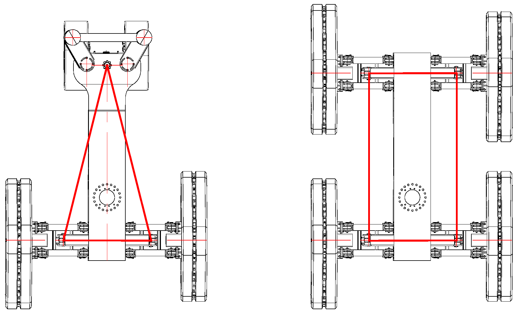
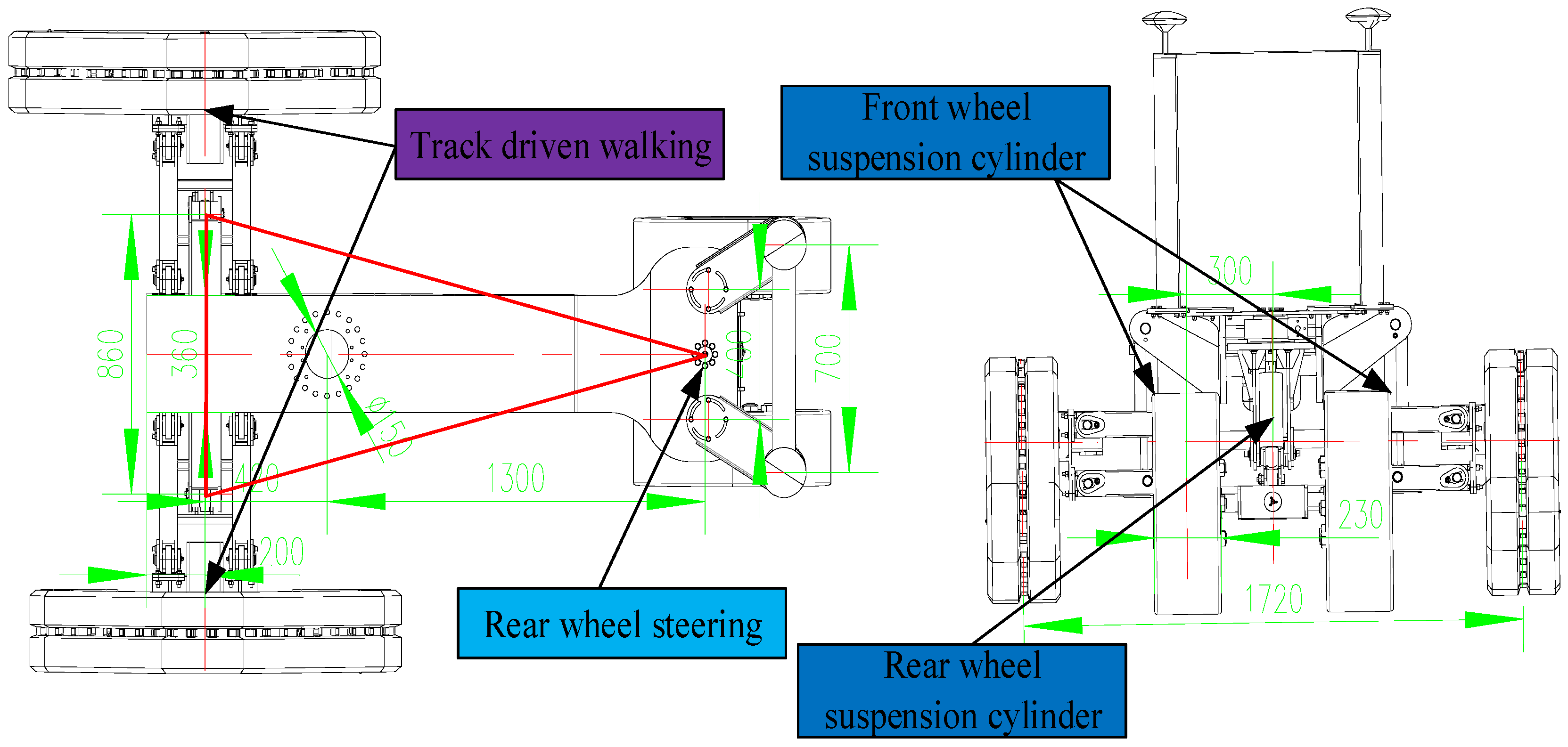
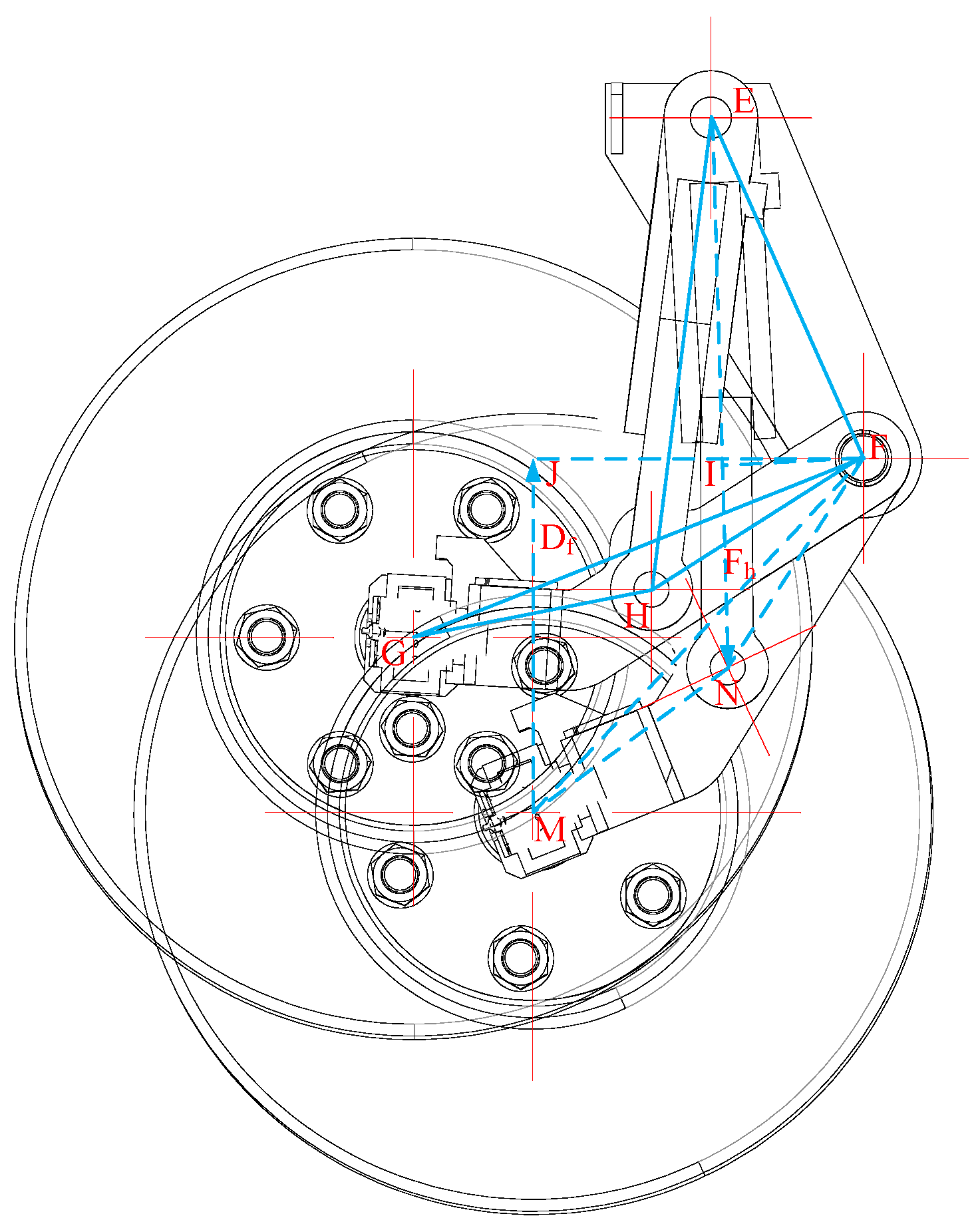
2.1. Chassis Structure

When designing the chassis structure of the photovoltaic panel cleaning robot, two different chassis layout methods of three wheels and four wheels were proposed from the perspective of road complexity, high drive and stability. The three-wheel type was driven by the wheel–track composite drive, and the four-wheel type was completely driven by the track. The layout is presented in Figure 3.
Through the comparison of three-wheel and four-wheel structures in different performance aspects in Table 2, it can be seen that the three-wheel structure reduces the weight of the whole machine by 30% and improves the lightweight of the whole machine. In terms of the turning radius, the three-wheel type uses rear-wheel steering, resulting in a small turning radius. The four-wheel type can only use differential steering, with a large turning radius and the possibility that the track may fall off during the steering process. In terms of leveling control strategy, the three-point leveling control strategy is simple and has fast response speed. The four-point leveling control strategy is relatively complex and the system response speed is slow.
In summary, the chassis of the photovoltaic panel cleaning robot adopts a three-wheel wheel–track composite drive form using rear-wheel steering to improve the adaptability of the vehicle in a complex environment.
The chassis structure was designed using Solidworks 2016 to adapt to complex road environments. The chassis structure design comprised three parts, i.e., track-driven walking device, front- and rear-wheel suspension device, and rear-wheel tire steering device. Each part was connected through the pin shaft structure. Using track wheels as the driving walking device can increase the contact area with the ground and improve traction force. The front- and rear-wheel suspension devices use three plunger cylinders to achieve adaptive leveling of the chassis. The rear tire steers independently, which can reduce the turning radius and improve the flexibility of the whole machine. The encoder was installed at its rotary center to achieve closed-loop control and improve the accuracy of control. As shown in Figure 4.
The three-point active suspension exhibits the advantages of simple structure and no over static problems. The leveling control strategy was simplified so that the response of the suspension system could be fast and stable. This ensured the capability of the robot to automatically level the road surface no matter how complex it is during walking so that the fast response of the active suspension and the stability of the upper arm during the cleaning process could be guaranteed.
The resistance change in the walking process of the photovoltaic panel cleaning machine affects the speed of the wheel-tracked vehicle. Only when the traction force generated by the vehicle is greater than or equal to the sum of all the resistance can the vehicle drive quickly. The resistance under the climbing road during vehicle driving is
{ F r = M g ( μ 1 + sin α ) F i = μ 2 ( F l 1 + F l 2 ) F a = 1 2 C ρ s v 2 F g = F r + F i + F a ,
where Fr denotes the rolling resistance, μ1 represents the rolling resistance coefficient, α expresses the slope; M is the overall weight, Fi is the resistance generated by the left and right track wheels, μ2 is the internal friction resistance coefficient, Fl1 and Fl2 are the internal resistance of the track, Fa is the air resistance, C is the air resistance coefficient; ρ expresses the density of air; s is the windward area of the object, v is the relative velocity of the object and air, Fg is the total resistance.
As depicted in Figure 5, as the vehicle speed and slope angle continued to increase, the resistance of the entire vehicle increased continuously. Combining the selected hydraulic drive motor parameters with the field environment, the slope angle was set between 0 and 10°, and the maximum speed was 0.7 m/s, conforming to the design requirements.
In the rear-wheel group of the photovoltaic panel cleaning robot, using track steering can lead to a large turning radius and easy occurrence of track detachment. The use of tire sets on the rear wheels can increase the ground-to-ground ratio and reduce the turning radius, thus improving the overall flexibility of the machine. When the whole machine was turning, the resistance torque of the rear tire group reached the maximum. The steering resistance torque was built using the Tablake recommended equation
T = 10 M h σ H m 2 8 + D 2 ,
where Mh is the load on the rear tire group, δ is the friction coefficient between the tire and the ground, Hm is the tire width, and D is the eccentricity; the width range and eccentricity range of the tire were set as well as the change in the steering resistance torque were analyzed.
As revealed by the analysis in Figure 6, with the rise in the tire width and eccentricity, the rear-wheel resistance torque increased continuously. In accordance with the selected rotary drive parameters, the solid tire with the tire width of 230 mm and an eccentricity of 300 mm was selected.
In the study of the turning radius of the photovoltaic panel cleaning robot, the three-wheel steering principle was built by combining the Ackerman steering principle because of the three-wheel steering method. The mapping relationship between the rear-wheel angle change and the turning radius was analyzed by a mathematical model.
In accordance with the three-wheel steering principle of Figure 7, the steering model was built as follows:
{ sin θ = L / R 1 R = H 2 + L 2 2 H = R 1 2 L 2 v l v r = L L + ( B / 2 ) tan θ ,
where R1 denotes the rear-wheel steering radius; R represents the chassis centroid steering radius; H expresses the front axle steering radius; L is the chassis wheelbase; L1 denotes the centroid distance from the rear axle distance; L2 is the centroid distance from the front axle distance, vl is the left track speed, vr is the left track speed; B expresses the front wheel track; θ represents the rear-wheel steering angle.
As indicated by the analysis in Figure 8, the turning radius of the front axle, center of mass, and rear axle was inversely proportional to the turning angle, and the turning radius was decreased with the increase in the turning angle. When the rear-wheel turning angle reached 45°, the maximum turning radius corresponding to the rear wheel exceeded 2 m, thus conforming to the design requirements. The speed ratio on the left and right sides of the track drive wheel was reduced with the rise in the turning angle of the rear wheel. At the turning angle of the rear wheel of 45°, the maximum speed ratio reached 0.71, conforming to the design requirements.
The rear-wheel suspension structure can be simplified into a planar slider–rocker mechanism as shown in Figure 9 [29]. EF is the suspension bracket connected with the rotary drive, and the rotary drive drives the whole rear-wheel suspension device to achieve steering. EH is the suspension hydraulic cylinder, and its telescopic length determines the lifting height of the rear wheel. FGH is the balance arm, which is connected to the suspension frame, the suspension hydraulic cylinder and the axle shaft through F, G and H three points, respectively.
When the suspension angle is ∠HFN and the displacement of the hydraulic cylinder is lEN, then
cos E F N = l E F 2 + l N F 2 l E N 2 2 l E F l N F .
EF is the suspension frame, which is connected with the rotary drive. The rotary drive drives the suspension mechanism to realize the steering. The force balance equation of the steering actuator is
F h l F I = D f l F M cos J F M .
In the formula, Fh is the output force of the hydraulic cylinder and Df is the rear-wheel suspension load force.
According to the triangle △EFN area formula,
l E F l H F sin ( E F H + H F N ) = l E N l F I .
According to Formulas (4)–(6), the relationship between the output force of the rear-wheel suspension cylinder and the load force can be solved.
F h D f = l F M cos J F M l E F 2 + l N F 2 2 l E F l F N cos E F N l E F l F H sin ( E F H + H F N ) .

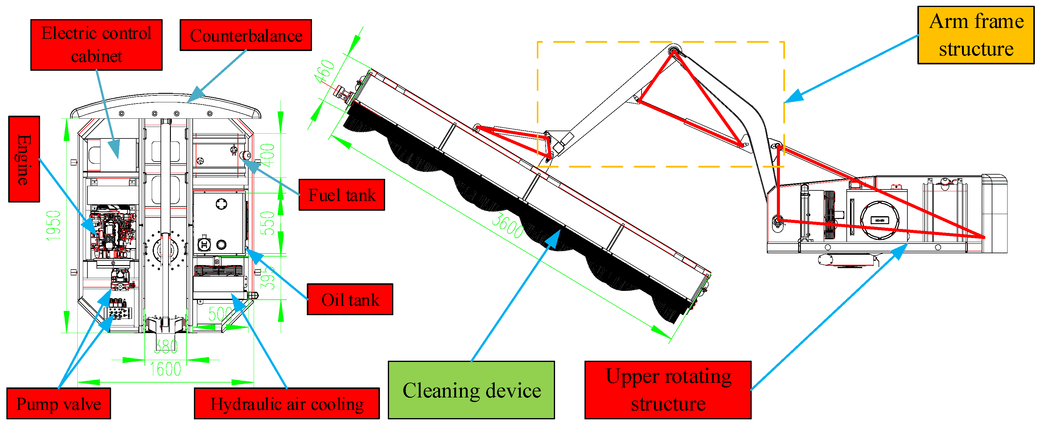
2.2. Upper Structure

In general, the composition of the upper structure comprised three parts, i.e., the upper rotating structure, the arm frame structure, and the cleaning device. The engine, load sensitive pump, multi-way valve group, electric control cabinet, fuel tank, etc., were installed in the upper turning structure of the vehicle to achieve the hydraulic drive of the entire vehicle. The triangular design of the boom structure was adopted to make the structure stable and ensure the stability of the cleaning device during operation. Three cylinders were used to drive the boom mechanism to rotate, and sensors were used to realize closed-loop control to improve the accuracy of control. The cleaning device was designed as a rolling brush structure which realizes the cleaning of dust particles on the smooth surface under the drive of the cleaning motor without hydration operation; in addition, this design reduces the cost of the device. All structures were connected and fixed by pins and bolts to ensure that the upper structure can meet the requirements of photovoltaic panel cleaning in harsh environments. As shown in Figure 10.
The cleaning device was designed with two sides of the scraper, and the brush was driven by the hydraulic motor to clean the dust particles on the photovoltaic panel surface. Both sides of the scraper can not only remove the dust particles on the plate surface, but also avoid the secondary pollution of the plate surface before and after cleaning.
In the design, it is necessary to study the mapping relationship between the hydraulic actuators of the boom and the joint angle and establish the coordinate system shown in Figure 11.
According to the coordinate system built by the above diagram, the mapping relationship between the displacement variation of the big arm, the small arm and the sweeper cylinder and the joint angle can be solved by geometric transformation, and the relationship is as follows:
{ L A B = L A C 2 + L B C 2 2 cos ( 180 ° B C D θ 2 ) L A C L B C θ 2 = 180 ° B C D a r cos ( L A C 2 + L B C 2 L A B 2 2 L A C L B C ) ,
{ L E F = L E D 2 + L D F 2 2 cos ( 180 ° E D H θ 3 ) L E D L D F θ 3 = 180 ° E D H a r cos ( L E D 2 + L D F 2 L E F 2 2 L E D L D F ) ,
{ L K G = L K H 2 + L H G 2 2 cos ( 180 ° + K H N G H D + θ 4 ) L K H L H G θ 4 = 180 ° + K H M G H D a r cos ( L K H 2 + L H G 2 L K G 2 2 L K H L H G ) ,
where LAB, LEF and LKG denote the displacement changes in the big arm cylinder, the small arm cylinder, and the sweeper cylinder, respectively; θ1, θ2 and θ3 represent the angle between the big arm and the upper frame, the angle between the small arm and the big arm, and the angle between the sweeping plates, respectively.
Combined with the established coordinate system and the angle variables of the boom mechanism, the Monte Carlo algorithm was used to solve the end trajectory space of the robot. The end space formed is described below.
As depicted in Figure 12, it can be seen that the end working space of the photovoltaic panel cleaning robot is similar to a hemispherical body; from the Y-Z working plane, it can be seen that the limit position that can be reached during forward and reverse cleaning is [−2.85 m, 2.85 m]; combined with the cleaning radius requirements of the photovoltaic panels, the effectiveness of the designed boom cleaning device was verified.
In general, the hydraulic system of the photovoltaic panel cleaning robot drove the entire machine through the load sensitive pump driven by the engine so that the normal operation requirements of the entire machine’s hydraulic system in low-temperature environments could be ensured. Following the different functional requirements of the entire machine, the upper control valve group and the chassis control valve group were designed. The upper control valve group mainly realizes the functions of upper rotation, arm posture adjustment, and front and back cleaning. The control valve group of the vehicle was mainly used to achieve the functions of front and rear travel of the track device, three-point leveling of the suspension system, and independent rear wheel drive. As shown in Figure 13.
In comparison with references [14,15,16,17,18,19,20,21,22], the self-propelled photovoltaic cleaning robot developed in this study showed the following advantages:
(1)
Intelligent and efficient: the boom device was adjusted adaptively with the height of the photovoltaic panel, the cleaning device completely covered the photovoltaic panel surface, and the fit and coverage were good.
(2)
Strong obstacle crossing and smooth operation: front-wheel track drive and rear-wheel tire steering resulted in high driving force and small turning radius. The chassis had independent active suspension, adaptive leveling, and adaptive adjustment of longitudinal and transverse slopes which can adapt to complex road conditions.
(3)
Unmanned and versatile: robots using RTK + GPS navigation system can achieve high-precision positioning and navigation operations, saving labor costs. According to the needs of photovoltaic power plants, robots can achieve a variety of purposes.
(4)
Anhydrous cleaning: to overcome the problems of large water resource consumption and poor cleaning effect in conventional cleaning methods, water resource consumption can be avoided and the cleaning cost of power plants can be reduced.

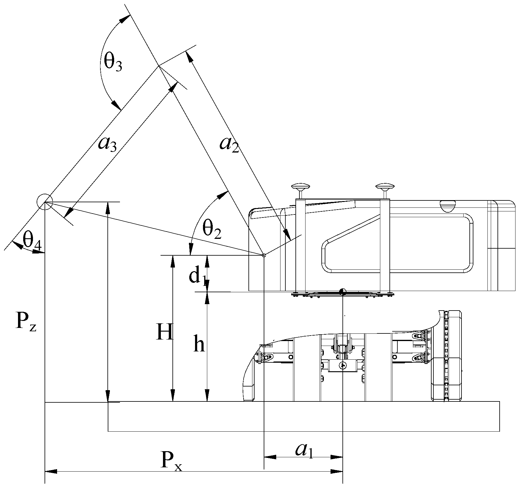
3. Robot Kinematics Model

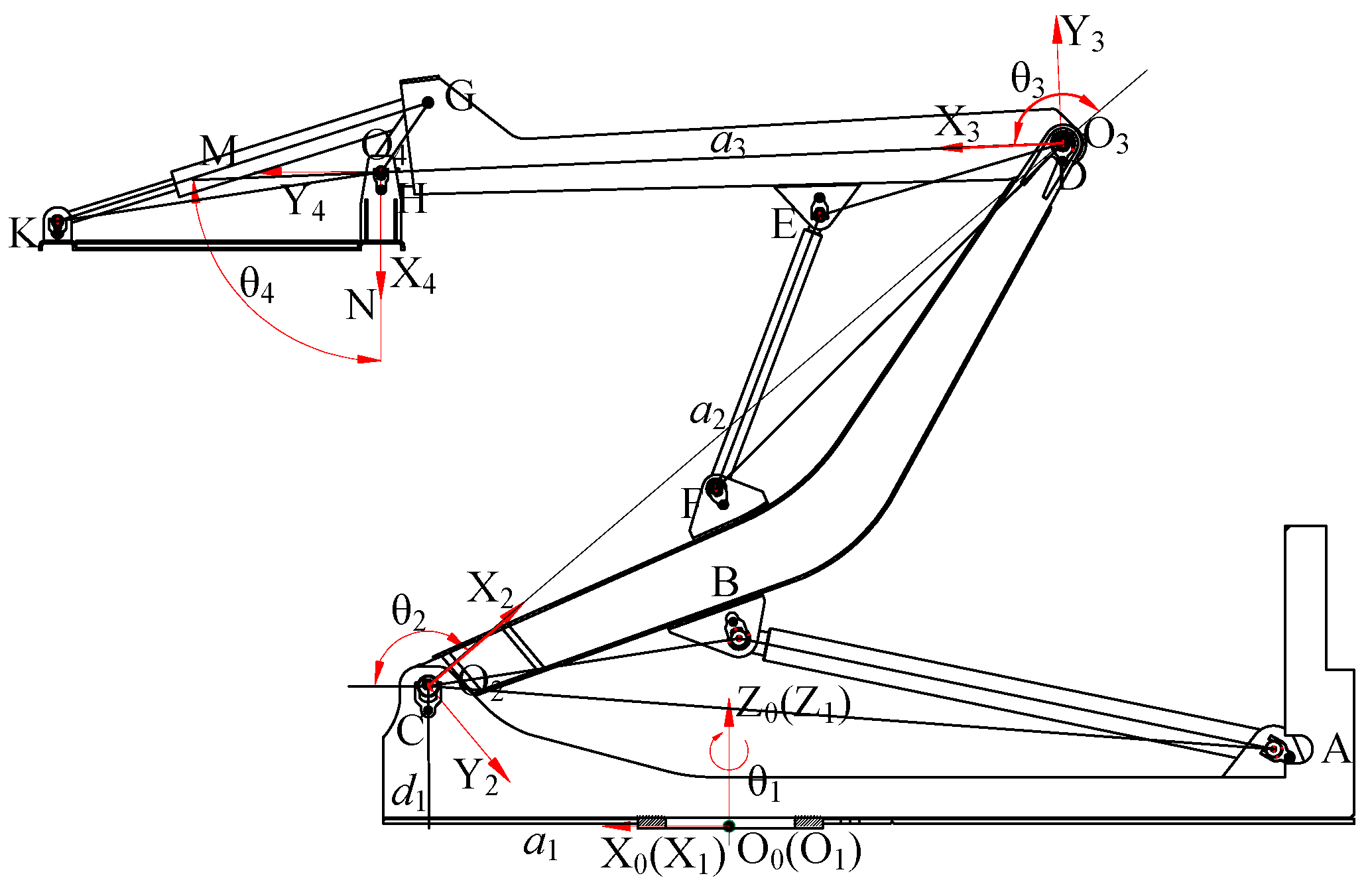
3.1. Kinematics Analysis

The parameters of the arm mechanism of the photovoltaic panel cleaning robot were determined based on the coordinates built in Figure 11. The parameter table is presented below (Table 3).
The kinematics equation of the end cleaning device relative to the base coordinate system was solved according to the forward kinematics solution to provide a theoretical basis for trajectory planning. The kinematics equation of the end cleaning device trajectory is
M 04 = M 01 M 12 M 23 M 34 = [ c 1 c 234 c 1 s 234 s 1 c 1 ( a 1 + a 2 c 2 + a 3 c 23 ) + d 4 s 1 s 1 c 234 s 1 s 234 c 1 s 1 ( a 1 + a 2 c 2 + a 3 c 23 ) d 4 c 1 s 234 c 234 0 a 2 s 2 + a 3 s 23 + d 1 0 0 0 1 ] .
The 3D space coordinate equation of the end trajectory of the cleaning device was determined using the forward solution of the kinematics equation of Equation (11):
{ p x = c 1 ( a 1 + a 2 c 2 + a 3 c 23 ) + d 4 s 1 p y = s 1 ( a 1 + a 2 c 2 + a 3 c 23 ) d 4 c 1 p z = a 2 s 2 + a 3 s 23 + d ξ = θ 2 + θ 3 + θ 4 .
The geometric relationship of the inverse kinematics of the photovoltaic panel cleaning robot is shown below (Figure 14).
According to the above geometric relationship and the end-pose matrix of the photovoltaic panel cleaning robot, the inverse kinematics of the joint variables of the robot arm frame mechanism can be solved. The inverse kinematics results are as follows:
{ θ 1 = arctan ( p x / p y ) θ 2 = arctan ( p z H p x a 1 ) + arcsin ( a 3 × sin ( θ 3 + 180 ° ) ( p x a 1 ) 2 + ( p z H ) 2 θ 3 = arccos ( a 2 2 + a 3 2 ( p x a 1 ) 2 ( p z H ) 2 2 × a 2 × a 3 ) 180 ° θ 4 = ζ θ 2 θ 3 .

3.2. Jacobian Matrix Solution for Arm Frame

The transformation between the Cartesian space motion velocity and the joint space motion velocity of a robotic arm is called the Jacobian matrix. The methods for constructing Jacobian matrices include vector product method and differential transformation method. In this paper, the differential transformation method was used to calculate the Jacobian matrix of the robot. The solution for the ith column of the Jacobian matrix is
J i = [ ( p × n ) z , ( p × o ) z , ( p × a ) z , n z , o z , a z ] T .
In the above equation, the n, o, and a vectors form the rotation transformation matrix for the transformation from the ith link coordinate system to the robot end coordinate system, while p is the position vector for the transformation from the ith link coordinate system to the robot-end coordinate system.
M 34 = [ cos ( θ 4 ) sin ( θ 4 ) 0 a 3 sin ( θ 4 ) cos ( θ 4 ) 0 0 0 0 1 d 4 0 0 0 1 ]
M 24 = M 23 M 34 = [ cos ( θ 3 + θ 4 ) sin ( θ 3 + θ 4 ) 0 a 3 × cos ( θ 3 ) + a 2 sin ( θ 3 + θ 4 ) cos ( θ 3 + θ 4 ) 0 a 3 × sin ( θ 3 ) 0 0 1 d 4 0 0 0 1 ]
M 14 = [ cos ( θ 2 + θ 3 + θ 4 ) sin ( θ 2 + θ 3 + θ 4 ) 0 a 3 × cos ( θ 2 + θ 3 ) + a 2 × cos ( θ 2 ) + a 1 0 0 1 d 4 sin ( θ 2 + θ 3 + θ 4 ) cos ( θ 2 + θ 3 + θ 4 ) 0 a 3 × sin ( θ 2 + θ 3 ) + a 2 × sin ( θ 2 ) 0 0 0 1 ]
For the fourth joint, Equation (15) is the transformation matrix from the connecting rod coordinate system to the end coordinate system of the joint. Values n, o, a, and p in Equation (15) were substituted for Equation (14) to obtain the Jacobian column vector J4.
J 4 = [ 0 , 0 , d 4 , 0 , 0 , 1 ] T .
For the third joint, Equation (16) is the transformation matrix from the connecting rod coordinate system to the end coordinate system of the joint. Values n, o, a, and p in Equation (16) were substituted for Equation (14) to obtain the Jacobian column vector J3.
J 3 = [ 0 , 0 , d 4 , 0 , 0 , 1 ] T .
For the second joint, Equation (17) is the transformation matrix from the connecting rod coordinate system to the end coordinate system of the joint. Values n, o, a, and p in Equation (17) were substituted for Equation (14) to obtain the Jacobian column vector J2.
J 2 = [ s 234 ( a 3 s 23 + a 3 s 2 ) , c 234 ( a 3 s 23 + a 3 s 2 ) , 0 , s 234 , c 234 , 0 ] T .
For the first joint, Equation (11) is the transformation matrix from the connecting rod coordinate system to the end coordinate system of the joint. Values n, o, i, and p in Equation (11) were substituted for Equation (14) to obtain the Jacobian column vector J1.
J 1 = [ s 234 ( a 3 s 23 + a 2 s 2 + d 1 ) , c 234 ( a 3 s 23 + a 2 s 2 + d 1 ) , 0 , s 234 , c 234 , 0 ] T .
The corresponding Jacobian matrix velocity solution is
J = [ J 1 , J 2 , J 3 , J 4 ] = [ s 234 ( a 3 s 23 + a 2 s 2 + d 1 ) s 234 ( a 3 s 23 + a 3 s 2 ) 0 0 c 234 ( a 3 s 23 + a 2 s 2 + d 1 ) c 234 ( a 3 s 23 + a 3 s 2 ) 0 0 0 0 d 4 d 4 s 234 s 234 0 0 c 234 c 234 0 0 0 0 1 1 ] .

4. Cleaning Plan for Photovoltaic Robot Arm

To improve the cleaning efficiency, smooth operation and reduce the probability of mechanical damage of the photovoltaic robot, the trajectory of the robot was planned to achieve autonomous operation of the trajectory.

4.1. Trajectory Discretization

When setting the target trajectory of the end cleaning device of the photovoltaic cleaning robot, the hydraulic system was used to drive the rotation center of the upper vehicle to rotate 90°, and the upper arm mechanism was extended to the maximum state, and then the arm mechanism was controlled to fall slowly so that the cleaning device would be in contact with the photovoltaic panel surface, achieving the cleaning operation of the photovoltaic panel surface.
According to the key points of the trajectory discretization of the end cleaning device of the photovoltaic cleaning robot, the key discrete points were converted from the pose space to the joint space through the inverse kinematics solution as shown in Table 4.

4.2. B Spline Function

Given n + 1 control points Di (i∈(0, n)), the expression of the definable k-degree B-spline curve can be defined as [30,31,32,33]
p ( u ) = i = 0 n D i N i , k ( u ) ,
where Ni,k (u) denotes the basis function of the B-spline curve.
In accordance with the deBoor–Cox recursion equation, it was derived as follows:
{ N i , 0 = { 1 , u i < u < u i + 1 0 , other N i , k ( u ) = u u i u i + k u i N i , k 1 ( u ) + u i + k + 1 u u i + k + 1 u i + 1 N i + 1 , k 1 ( u ) 0 0 = 0 .
As indicated by the above equation, Ni,k (u) denotes the ith B-spline basis function; the basis function interval u ∈ [ui, ui+k+1]; U = [u0, u1, …, un+2k] represents the node vector. Accordingly, any interval u ∈ [ui, ui+1] that covered at most k + 1 B-splines Nj,k(u)(j = ik, ik + 1, …, i) was nonzero in this interval so that the B-spline curve equation can also be expressed as
p ( u ) = j = i k i d j N j , k ( u ) , u [ u i , u i + 1 ] ,
where ui was determined by combining the cumulative chord length parameterization method and the average value method:
{ u 0 = u 1 = = u k = 0 u j + k = 1 k i = j j + k 1 u i , j ( 1 , n k ) u n + 1 = u n + 2 = = u n + k + 1 = 1 .
Following the deBoor–Cox recursive equation, the rth derivative pl(u) of kth degree non-uniform B-spline curve was derived, and its equation is written as follows:
{ p l ( u ) = r = i k + l i d l r N r , k l ( u ) , u [ u i , u i + 1 ] d l r = { d j ( k + 1 l ) d r l 1 d r 1 l 1 u r + k - l u r , l [ 1 , i k + l ] .
To make the respective joint trajectory pass through n + 1 position nodes in Q, the control point dr of the B-spline trajectory equation should be reversed. From the time−position sequence, n + 1 equations can be listed as follows:
p ( u i + k ) = r = i i + k d r N r , k ( u ) = p i , i [ 0 , n ] .
By configuring the boundary conditions, the control vertex equation of the j joint can be described as a matrix form below:
A j d j = p j .
In the above equation, Aj∈R(n+k)×(n+k); dj = [dj,0, dj,1,…, dj,(n+3), dj,(n+4)]; pj = [pj,0, pj,1,…, pj,(n+3), pj,(n+4)].

4.3. Trajectory Optimization of Improved Sparrow Algorithm

The Sparrow Algorithm refers to an intelligent optimization algorithm proposed through the foraging and anti-predation behavior of sparrow populations [34,35]. The advantages of the sparrow algorithm are elucidated as follows. (1) The search basis was the objective function value, which was slightly dependent on the problem and can be adopted to solve linear, nonlinear, continuous, discrete, and other problems. (2) There were fewer parameters affecting the performance of the algorithm, and fewer parameters should be changed when solving practical problems, which can be implemented conveniently. (3) Its update method was similar to those of other swarm intelligence algorithms, with a certain adaptive mechanism and stronger search ability [36,37].

4.3.1. Time-Optimal Objective Function

Multiple discrete path points f(q) = (ti, qij) were taken in the joint space trajectory planning of the photovoltaic panel cleaning robot, where i∈(0, n), j∈(1, N), N denotes the number of joints of the boom, n + 1 expresses the number of path points passed by the end cleaning device when the photovoltaic cleaning robot is running, qij represents the joint angle value of the j joint at ti time.
To increase work efficiency, the sum of time intervals between robot path points was defined as the time optimization objective function during the cleaning of the photovoltaic panel surface by the photovoltaic panel cleaning robot.
h ( t ) = min i = 1 n 1 ( t i + 1 t i ) .
Following the operating conditions and structural design requirements of the photovoltaic panel cleaning robot, the angular velocity, angular acceleration, and angular acceleration of the respective joint of the boom were constrained for smoothness and continuity of the running trajectory.

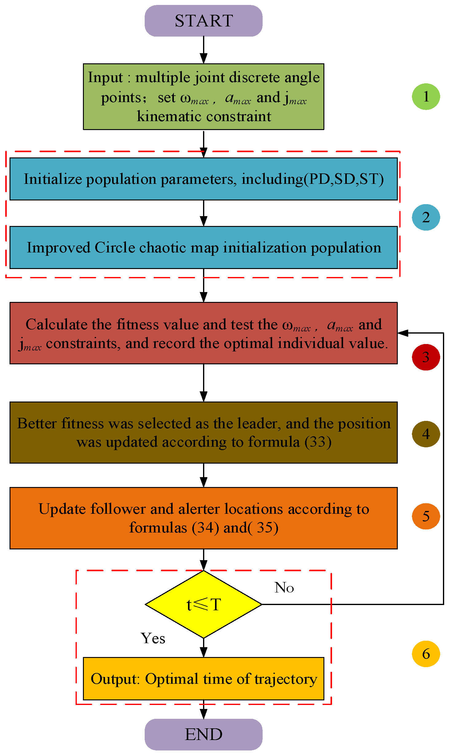
4.3.2. Improved Sparrow Algorithm

In general, the limitations of conventional sparrow algorithms were elucidated as follows. (1) At the population initialization stage, sparrow individuals were generated at random positions in the solution space. Under the good initial position of the randomly generated population, the algorithm was more likely to find the optimal position. In contrast, the optimization efficiency of the algorithm was likely to decline, which cannot ensure the diversity of the population and the stability of the algorithm. (2) The decrease in population diversity at the discoverer and follower stages, as well as the decrease in communication between groups at the vigilance stage, could result in the reduced local search ability of the algorithm [38,39].
To address the limitation of the algorithm, the Circle chaotic map was introduced to initialize the population and increase the population diversity for improving the quality of the initial solution. The nonlinear weight factor was introduced to enhance the search ability and convergence speed. The position update method of followers and early warnings was adjusted to solve the problem of sparrow algorithm falling into local optima.
(1)
Improved Circle chaotic map initialization
The sparrow algorithm was randomly generated during initialization so that the initial solution turned out to be easy to aggregate, the solution space coverage was not high, and the difference between individuals was low. The abovementioned phenomenon can be improved by the chaotic map initialization population. Currently, there are many types of chaotic maps, and Circle maps have been extensively used for their stability and high coverage of chaotic values. However, the chaotic values of the Circle map remained unevenly distributed, and the values between [0.2, 0.6] were denser. The Circle map equation should be optimized to make the chaotic value distribution more uniform [40,41].
x n + 1 = mod ( 2 x n + 0.5 ( 0.7 2 π ) sin ( 2 π x n ) , 1 ) ,
where n denotes the dimension of the solution, xn ∈ [0, 1]. n was taken as 5000 to display the improvement effect visually and clearly. The optimized initial solution dimension distribution and initial solution dimension distribution histogram are presented below.
As depicted in Figure 15 and Figure 16, the optimized Circle map had a more uniform distribution of chaotic values. Using the optimized Circle map to initialize the population can enhance the diversity of the population so that the optimization ability of the Sparrow algorithm can be enhanced.
(2)
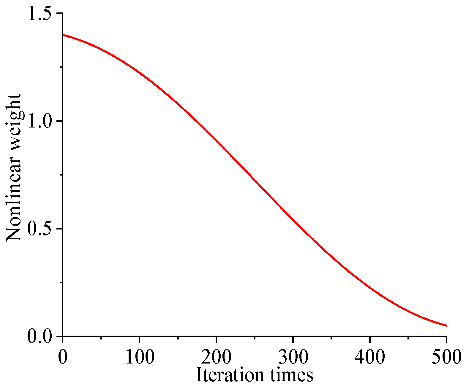
Nonlinear weighting factor
The optimization process of the algorithm can be divided into global search and local search. In the early stage of evolution, global search plays a major role in finding the global optimal solution. To prevent falling into local optimum, the global optimal solution of the previous generation can be introduced so that the location of the discoverer can be affected by the previous generation. Therefore, the introduction of nonlinear weights can not only balance global search and local search, but also prevent falling into local optimum.
ω = ω max ( ( ω max ω min ) t / T ) + ( ω max ω min ) cos ( π t / T ) ,
where ωmax and ωmin represent the inertia weight at the beginning and end of the iteration, respectively; t expresses the current number of iterations; T expresses the maximum number of iterations. The nonlinear weight factor change curve is illustrated below.
As depicted in Figure 17, with the rise on the number of iterations, the inertia weight tended to decline nonlinearly. The reason for this result is that when the iteration begins, the larger inertia weight can improve the search ability of the algorithm; at the end of the iteration, the smaller inertia weight can enhance the development ability of the algorithm while accelerating the convergence of the algorithm to a certain extent.
(3)
Updates of leaders, followers and alerters [42]
By introducing the previous generation of global optimal solution and dynamic weight factor into the leader update equation, the algorithm can avoid falling into local optimum and improve the convergence speed. The optimized equation is as follows:
X i , j t + 1 = { ( X i , j t + ω ( f j , g t X i , j t ) ) r a n d , R 2 < S T X i , j t + Q , R 2 S T ,
where X i , j t We represents the position of the ith sparrow in the jth dimension when the number of iterations is t, f i , j t is the global optimal solution of the jth dimension in the previous generation, Q is a random number obeying (0, 1) normal random distribution, R2 represents the warning value, and ST is the safety value.
The iterative equation for follower position is as follows:
X i , j t + 1 = { Q exp ( ( X w o r s t t X i , j t ) / i 2 ) , i > N 2 X p t + 1 + | X i , j t X p t + 1 | A + L , i N 2 ,
where X w o r s t t denotes the position of the sparrow with the worst fitness when the number of iterations is t; X p t + 1 represents the position of the sparrow with the best fitness when the number of iterations is t + 1. If A refers to a matrix of 1 row and d columns, and the respective element is randomly set to 1 or −1, A+ = AT(AAT)−1, N represents the population size, L represents a matrix with 1 row and d columns, and each element is 1.
As indicated by the optimized warning update equation, if the sparrow is in the optimal position, it will randomly fly to any position between the optimal position and the worst position. If the sparrow is not in the optimal position, it will fly randomly to any position between the current position and the optimal position.
X i , j t + 1 = { ( X b e s t t + β ( X i , j t X b e s t t ) ) , f i f g ( X b e s t t + β ( X w o r s t t X b e s t t ) ) , f i = f g   ,
where X b e s t t represents the individual position of the sparrow with the best global fitness when the number of iterations is t; β expresses a normal distribution random number subject to (0, 1); fi and fg represent the fitness of the current sparrow individual and the fitness of the globally optimal individual, respectively.
The steps for optimizing the trajectory time of the photovoltaic panel cleaning robot arm for the optimized sparrow algorithm are as follows (Figure 18):
Step 1: Set the starting point, path point, and end point based on the key discrete angle values of the respective joint of the arm frame mechanism in Table 4; set ωmax, amax and jmax constraints of each joint during operation;
Step 2: Initialize the population parameters, including the number of leaders PD, the number of alerts SD and the safety value ST using Equation (31) to improve the Circle chaotic map to initialize the sparrow population;
Step 3: Calculate the fitness value of the respective sparrow, verify whether the constraints of ωmax, amax and jmax are met, and record the current optimal fitness value and corresponding position;
Step 4: Select the better sparrow from the fitness value, select some sparrows as leaders, and update the position through Equation (33);
Step: 5: Update the positions of followers and alerts through Equations (34) and (35);
Step 6: Determine whether the optimization time t is less than the given time T. If it is less than that, the program ends and the optimal trajectory time is output; if it is greater than that, return to Step 3 and run again.

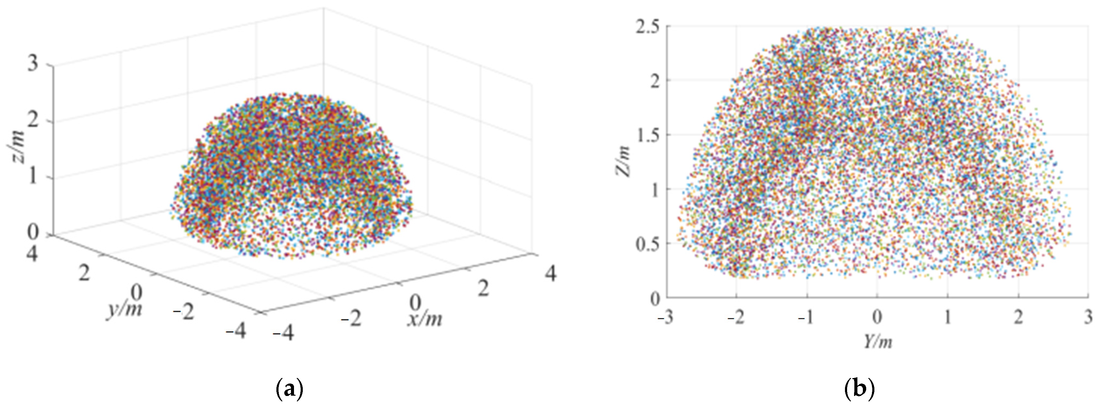
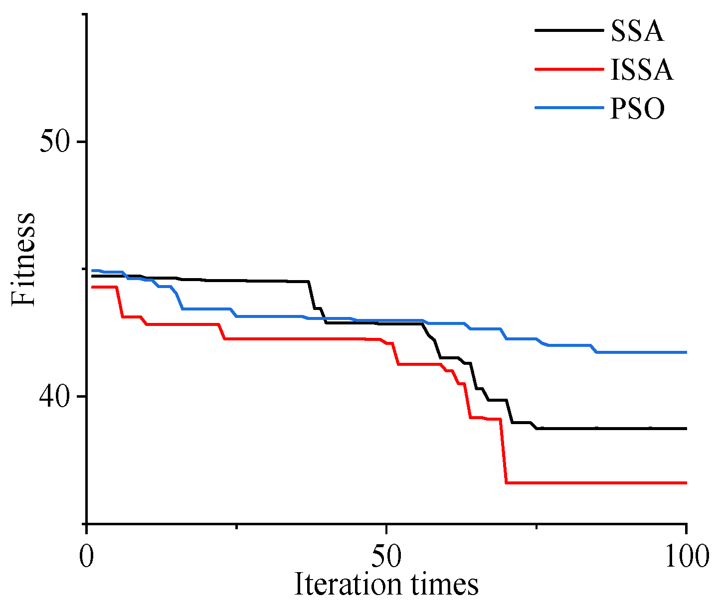
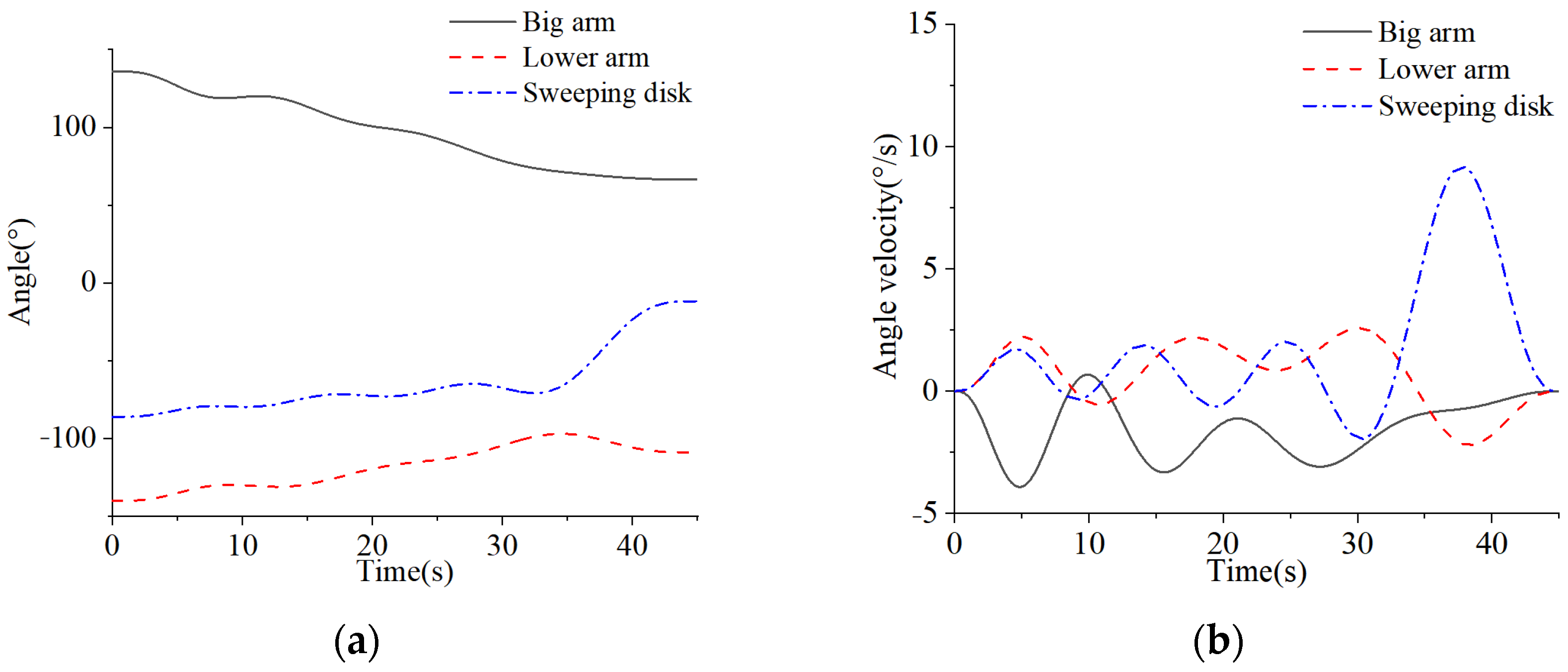
4.4. Simulation Analysis

The discrete path points of the operation trajectory of the end cleaning device in Table 4 were selected, and the general parameters of the sparrow algorithm were set. To be specific, the population size was 20, the iteration number was 100, the leader proportion was 20%, the early warning proportion was 10%, and the early warning value was 0.8. For the PSO algorithm parameters, the population size was 30, the iteration number was 100, the maximum inertia weight was 0.9, and the minimum inertia weight was 0.4. To ensure the stability of the boom during operation, the angular velocity constraint of the respective path segment was set to 10°/s, the angular acceleration of each path segment was 3°/s2, and the angular acceleration of the respective path segment was 3°/s3; the time interval between each path point reached [6 s, 5 s, 5 s, 7 s, 5 s, 7 s, 10 s], with a total time of 45 s. The three algorithms implemented the overall time-optimal trajectory planning for the upper arm of the photovoltaic panel cleaning robot, and the corresponding convergence curve of the fitness of the particles of the entire manipulator are presented in the following figure.
As depicted in Figure 19, the conventional sparrow algorithm, particle swarm optimization algorithm and optimized sparrow algorithm had a significant gap in convergence speed and convergence accuracy, and the optimized sparrow algorithm achieved global optimization faster. The optimized sparrow algorithm was adopted to optimize the running time of the end cleaning device, i.e., 5.7105 s, 2.4892 s, 2.9650 s, 6.5524 s, 3.8436 s, 5.7837 s, and 9.2612 s. The total time was reduced from 45 s to 36.6057 s, which notably increased the running speed and the working efficiency of cleaning photovoltaic panels. As revealed by the above result, it is feasible and efficient to use the optimized sparrow algorithm to plan the time-optimal trajectory of the boom mechanism.
In accordance with the optimized sparrow algorithm, the time-optimal solution was performed under the condition that the kinematics constraints of the respective joints of the boom were satisfied. Moreover, the following figure presents the angle, angular velocity, angular acceleration, and angular acceleration of the respective joints of the boom mechanism of the photovoltaic plate cleaning robot before and after the output optimization.
As depicted in Figure 20 and Figure 21, the angle changes of the respective joints of the photovoltaic panel cleaning robot arm were continuous and stable, and no sudden change was identified. Prior to optimization, the maximum angular velocity reached 9.19681°/s, the maximum angular acceleration was 2.38377°/s2, and the maximum angular acceleration was 1.06539°/s3. After optimization, the maximum angular velocity reached 9.9761°/s, the maximum angular acceleration was 2.916°/s2, and the maximum angular acceleration was 1.4983°/s3. The angular velocity, angular acceleration, and angular acceleration of the respective joint conformed to the set constraints so that the stability of the respective joint of the boom during the running time was ensured, the running time of the boom trajectory was effectively reduced by 18.65%, and the cleaning efficiency of the photovoltaic panel was increased.

5. Experimental Research

The cleaning trajectory of the photovoltaic panel cleaning robot arm was studied experimentally to investigate the reliability of the optimal trajectory planning based on the optimized sparrow algorithm combined with the seven-order non-uniform B-spline curve interpolation time. During the experiment, through the mapping relationship between the joint space and the drive space, the displacement variable of the hydraulic actuator was converted into the angle variable, and the angle sensor was used to realize the closed-loop control of the respective joint angle to improve the accuracy of the control. The sensor installation position of the respective joint of the boom is shown below.
During the experimental process, the functions of the three joint angle variables over time after fitting the seven-degree non-uniform B-spline curve were used as input variables. The inclination angles of the respective joint detected by the sensors installed on the arm mechanism were fed back to the controller through the bus and compared with the input. The difference was then used as the input of the control system to control the action of the multi-way valve, achieving closed-loop control, thereby improving the accuracy of system control and avoiding damage to the photovoltaic panel surface caused by low precision control of the end cleaning device. The trajectory tracking curve and cleaning effect of the respective joint of the arm frame before and after optimization are shown in the following Figure 22.
As depicted in Figure 23 and Figure 24, during the autonomous cleaning operation of the photovoltaic panel cleaning robot, the respective joint angle ran smoothly and continuously during the trajectory tracking process with high curve overlap, thus confirming the effectiveness of the optimized sparrow algorithm combined with the time-optimal trajectory of the seven-degree non-uniform B-spline curve. During the cleaning process, there was no damage to the photovoltaic panel surface and the cleaning effect was good, which can achieve intelligent cleaning of the photovoltaic panel surface, increase work efficiency, and save labor costs.
As depicted in Figure 25, by analyzing the trajectory tracking error curves before and after optimization, it can be seen that the angle errors generated during the trajectory tracking control process of each joint before optimization are [−1.4°, 1.2°], [−1.2°, 1.1°], [−1.3°, 1.2°], and the trajectory tracking errors of each joint after optimization are [−1.7°, 1.3°], [−1.6°, 1.3°], and [−1.5°, 1.4°], which are all within the allowable range. Although the optimized trajectory tracking error has increased, the trajectory running time has decreased by 18.7%, and there has been no safety warning during the cleaning process, which meets the requirements of actual cleaning conditions and proves the reliability of its trajectory control.

6. Conclusions

A novel type of hydraulic driven self-propelled photovoltaic panel cleaning robot was proposed to address the disadvantages of the conventional cleaning method of dust particles on photovoltaic panels. The chassis adopted a three-wheel independent suspension design scheme with crawler wheel drive and rear-tire steering so that it is capable of adapting to the working requirements in harsh environments, reducing the turning radius and improving the turning flexibility. The three-joint series boom structure was developed to carry the end cleaning device, and multiple detection components (e.g., angle sensor and inclinometer) were installed to realize the intelligent control of boom cleaning. The cleaning device employed a roller brush to clean the photovoltaic panel surface for non-hydrated cleaning operations and save water resources.
The kinematics model of the boom mechanism was built and optimized with the end cleaning device of the upper arm structure as the research object. Circle chaotic mapping initialization and nonlinear weighting factor led to the increased initialization population diversity, search ability and convergence speed of the sparrow algorithm. The time optimal planning of the boom trajectory was performed using the seven-degree non-uniform B-spline curve. The reliability and effectiveness of the time-optimal trajectory planning were proved through the combination of simulation and experiment, and the cleaning efficiency of the robot to the dust of the photovoltaic panel was notably optimized.

Author Contributions

Conceptualization, R.G. and Y.G.; methodology, Y.G. and J.Z.; software, J.Y. and X.Z.; formal analysis, J.Y.; data curation, X.Z.; writing—original draft preparation, J.Y.; writing—review and editing, J.Y. and R.G.; supervision, Y.G.; funding acquisition, R.G. All authors have read and agreed to the published version of the manuscript.

Funding

This research was funded by the National Natural Science Foundation of China (12173054, 52075469).

Institutional Review Board Statement

Not applicable.

Informed Consent Statement

Not applicable.

Data Availability Statement

Not applicable.

Conflicts of Interest

The authors declare no conflict of interest.

References

  1. Abderrezek, M.; Fathi, M. Experimental study of the dust effect on photovoltaic panels’ energy yield. Sol. Energy 2017, 142, 308–320. [Google Scholar] [CrossRef]
  2. Kazem, H.; Chaichan, M. Experimental analysis of the effect of dust’s physical properties on photovoltaic modules in Northern Oman. Sol. Energy 2016, 139, 68–80. [Google Scholar] [CrossRef]
  3. Liu, F.; Zhang, Z.; Zhao, Y.; Zhu, Z.; Pan, W.; Wang, L.; Bin, X. A method of calculating the daily output power reduction of PV modules due to dust deposition on its surface. IEEE J. Photovolt. 2019, 9, 881–887. [Google Scholar] [CrossRef]
  4. Nepal, P.; Korevaar, M.; Ziar, H.; Isabella, O.; Zeman, M. Accurate soiling ratio determination with incident angle modifier for PV modules. IEEE J. Photovolt. 2018, 9, 295–301. [Google Scholar] [CrossRef] [Green Version]
  5. Wang, Z.; Xu, Z.; Zhang, Y.; Xie, M. Optimal cleaning scheduling for photovoltaic systems in the field based on electricity generation and dust deposition forecasting. IEEE J. Photovolt. 2020, 10, 1126–1132. [Google Scholar] [CrossRef]
  6. Klugmann-Radziemska, E.; Rudnicka, M. Decrease in photovoltaic module efficiency because of the deposition of pollutants. IEEE J. Photovolt. 2020, 10, 1772–1779. [Google Scholar] [CrossRef]
  7. Khadka, N.; Bista, A.; Adhikari, B.; Shrestha, A.; Bista, D.; Adhikary, B. Current practices of solar photovoltaic panel cleaning system and future prospects of machine learning implementation. IEEE Access 2020, 8, 135948–135962. [Google Scholar] [CrossRef]
  8. Sun, D.; Böhringer, K. An active self-cleaning surface system for photovoltaic modules using anisotropic ratchet conveyors and mechanical vibration. Microsyst. Nanoeng. 2020, 6, 87. [Google Scholar] [CrossRef]
  9. Mazumder, M.; Horenstein, M.; Stark, J.; Girouard, P.; Sumner, R.; Henderson, B.; Sadder, O.; Hidetaka, I.; Biris, A.; Sharma, R. Characterization of electrodynamic screen performance for dust removal from solar panels and solar hydrogen generators. IEEE Trans. Ind. Appl. 2013, 49, 1793–1800. [Google Scholar] [CrossRef]
  10. Lange, K.; Bahattab, M.; Alqahtani, S.; Mirza, M.; Glaubitt, W.; Naumann, V.; Hagendorf, C.; Ilse, K. Combined soiling and abrasion testing of antisoiling coatings. IEEE J. Photovolt. 2019, 10, 243–249. [Google Scholar] [CrossRef]
  11. Rifai, A.; Dheir, N.; Yilbas, B.; Khaled, M. Mechanics of dust removal from rotating disk in relation to self-cleaning applications of PV protective cover. Sol. Energy 2016, 130, 193–206. [Google Scholar] [CrossRef]
  12. Lu, H.; Cai, R.; Zhang, L.; Lu, L.; Zhang, L. Experimental investigation on deposition reduction of different types of dust on solar PV cells by self-cleaning coatings. Sol. Energy 2020, 206, 365–373. [Google Scholar] [CrossRef]
  13. Shehri, A.; Parrott, B.; Carrasco, P.; Saiari, H.; Taie, I. Impact of dust deposition and brush-based dry cleaning on glass transmittance for PV modules applications. Sol. Energy 2016, 135, 317–324. [Google Scholar] [CrossRef]
  14. Fan, S.; Liang, W.; Wang, G.; Zhang, Y.; Cao, S. A novel water-free cleaning robot for dust removal from distributed photovoltaic (PV) in water-scarce areas. Sol. Energy 2022, 241, 553–563. [Google Scholar] [CrossRef]
  15. Antonelli, M.; Zobel, P.; Marcellis, A.; Palange, E. Autonomous robot for cleaning photovoltaic panels in desert zones. Mechatronics 2020, 68, 102372. [Google Scholar] [CrossRef]
  16. Cai, S.; Bao, G.; Ma, X.; Wu, W.; Bian, G.; Rodrigues, J.; Albuquerque, V. Parameters optimization of the dust absorbing structure for photovoltaic panel cleaning robot based on orthogonal experiment method. J. Clean. Prod. 2019, 217, 724–731. [Google Scholar] [CrossRef]
  17. Khan, M.; Abbas, M.; Khan, M.; Kousar, A.; Alam, M.; Massoud, Y.; Jafri, S. Modeling and design of low-cost automatic self cleaning mechanism for standalone micro PV systems. Sustain. Energy Technol. Assess. 2021, 43, 100922. [Google Scholar] [CrossRef]
  18. Ölmez, B.; Ergezer, Ö.; Güğül, G. Autonomous solar panel cleaning robot with rubber wheeled and air-absorbing motor. Int. J. Energy Appl. Technol. 2021, 8, 182–187. [Google Scholar] [CrossRef]
  19. Hou, Y.; Fu, Y.; Chen, J. Analysis on dynamic feature of cross arm light weighting for photovoltaic panel cleaning device in power station based on power correlation. Open Phys. 2020, 18, 492–503. [Google Scholar] [CrossRef]
  20. Nguyen, M.; Truong, C.; Nguyen, V.; Duong, V.; Nguyen, H.; Nguyen, T. Research on Adhesive Coefficient of Rubber Wheel Crawler on Wet Tilted Photovoltaic Panel. Appl. Sci. 2022, 12, 6605. [Google Scholar] [CrossRef]
  21. Jang, W.; Kim, J.; Lee, S.; Kim, D. Mechanism design for walking typed solar panel-cleaning robot using triple driving lines. IAES Int. J. Robot. Autom. 2023, 12, 1. [Google Scholar] [CrossRef]
  22. Parrott, B.; Zanini, P.; Shehri, A.; Kotsovos, K.; Gereige, I. Automated, robotic dry-cleaning of solar panels in Thuwal, Saudi Arabia using a silicone rubber brush. Sol. Energy 2018, 171, 526–533. [Google Scholar] [CrossRef]
  23. Divyavani, G.; Chinnaaiah, M.; Dubey, S.; Asharani, P.; Kalyani, P. An Unveiling System to Clean Solar Panels with FPGA Based Robots. Inter. J. Pure Appl. Math. 2018, 118, 1–14. [Google Scholar]
  24. Amin, A.; Wang, X.; Alroichdi, A.; Ibrahim, A. Designing and Manufacturing a Robot for Dry-Cleaning PV Solar Panels. Int. J. Energy Res. 2023, 2023, 1–15. [Google Scholar] [CrossRef]
  25. Al-Jarrah, A.; Al-Jarrah, R.; Al-Momani, F.; Ababneh, M.; AI-Hajji, M. Two-Dimensional Movement Photovoltaic Cleaning Robot with Speed Control. Int. J. Mech. Eng. Robot. Res. 2022, 11, 151–158. [Google Scholar] [CrossRef]
  26. Morando, L.; Recchiuto, C.; Calla, J.; Scuteri, P.; Sgorbissa, A. Thermal and Visual Tracking of Photovoltaic Plants for Autonomous UAV Inspection. Drones 2022, 6, 347. [Google Scholar] [CrossRef]
  27. Rehman, S.; Mohandes, M.; Hussein, A.; Alhems, L.; AI-Shaikhi, A. Cleaning of Photovoltaic Panels Utilizing the Downward Thrust of a Drone. Energies 2022, 15, 8159. [Google Scholar] [CrossRef]
  28. Gupta, V.; Sharma, M.; Pachauri, R.; Babu, K. Design and development of self-cleaning PV sliding system. Clean Energy 2022, 6, 392–403. [Google Scholar] [CrossRef]
  29. Wang, J.; Zhao, J.; Li, W.; Jia, X.; Wei, P. Research and improvement of the hydraulic suspension system for a heavy hydraulic transport vehicle. Appl. Sci. 2020, 10, 5220. [Google Scholar] [CrossRef]
  30. Li, S.; Zhang, X. Research on planning and optimization of trajectory for underwater vision welding robot. Array 2022, 16, 100253. [Google Scholar] [CrossRef]
  31. Cheng, Q.; Hao, X.; Wang, Y.; Xu, W.; Li, S. Trajectory planning of transcranial magnetic stimulation manipulator based on time-safety collision optimization. Robot. Auton. Syst. 2022, 152, 104039. [Google Scholar] [CrossRef]
  32. Nie, M.; Zou, L.; Zhu, T. Jerk-Continuous Feedrate Optimization Method for NURBS Interpolation. IEEE Access 2023, 11, 25664–25681. [Google Scholar] [CrossRef]
  33. Wang, G.; Chen, J.; Zhou, K.; Pang, Z. Industrial Robot Contouring Control Based on Non-Uniform Rational B-Spline Curve. Symmetry 2022, 14, 2533. [Google Scholar] [CrossRef]
  34. Yan, S.; Liu, W.; Li, X.; Yang, P.; Wu, F.; Yan, Z. Comparative Study and Improvement Analysis of Sparrow Search Algorithm. Wirel. Commun. Mob. Comput. 2022, 2022, 4882521. [Google Scholar] [CrossRef]
  35. Gao, B.; Shen, W.; Guan, H.; Zheng, L.; Zhang, W. Research on multistrategy improved evolutionary sparrow search algorithm and its application. IEEE Access 2022, 10, 62520–62534. [Google Scholar] [CrossRef]
  36. Zheng, Y.; Li, L.; Qian, L.; Cheng, B.; Hou, W.; Zhuang, Y. Sine-SSA-BP Ship Trajectory Prediction Based on Chaotic Mapping Improved Sparrow Search Algorithm. Sensors 2023, 23, 704. [Google Scholar] [CrossRef] [PubMed]
  37. Gharehchopogh, F.; Namazi, M.; Ebrahimi, L.; Abdollahzadeh, B. Advances in sparrow search algorithm: A comprehensive survey. Arch. Comput. Methods Eng. 2023, 30, 427–455. [Google Scholar] [CrossRef] [PubMed]
  38. Nguyen, T.; Ngo, T.; Dao, T.; Nguyen, T. Microgrid operations planning based on improving the flying sparrow search algorithm. Symmetry 2022, 14, 168. [Google Scholar] [CrossRef]
  39. Kathiroli, P.; Selvadurai, K. Energy efficient cluster head selection using improved Sparrow Search Algorithm in Wireless Sensor Networks. J. King Saud Univ. Comput. Inf. Sci. 2022, 34, 8564–8575. [Google Scholar] [CrossRef]
  40. Zhang, D.; Xu, H.; Wang, Y.; Song, T.; Wang, Y. Whale optimization algorithm for embedded Circle mapping and onedimensional oppositional learning based small hole imaging. Control Decis. 2021, 36, 1173–1180. [Google Scholar]
  41. Song, L.; Chen, W.; Chen, W.; Lin, Y.; Sun, T. Improvement and application of hybrid strategy-based sparrow search algorithm. J. Beijing Univ. Aeronaut. Astronaut 2022, 1–16. [Google Scholar] [CrossRef]
  42. Liu, L.; Liang, J.; Guo, K.; Ke, C.; He, D.; Chen, J. Dynamic Path Planning of Mobile Robot Based on Improved Sparrow Search Algorithm. Biomimetics 2023, 8, 182. [Google Scholar] [CrossRef] [PubMed]
Figure 1. Three-dimensional design of cleaning robot.
Applsci 13 06967 g001
Figure 2. Robot cleaning operation.
Applsci 13 06967 g002
Figure 3. Different chassis structure layout.
Applsci 13 06967 g003
Figure 4. Wheel–track chassis structure.
Applsci 13 06967 g004
Figure 5. Relationship between total resistance and slope angle, vehicle speed.
Applsci 13 06967 g005
Figure 6. The relationship between rear-wheel resistance torque and tire width, eccentricity.
Applsci 13 06967 g006
Figure 7. Working principle of rear-wheel steering.
Applsci 13 06967 g007
Figure 8. Relationship between rear-wheel steering angle and turning radius, front-wheel speed ratio. (a) Turning radius; (b) speed ratio.
Applsci 13 06967 g008
Figure 9. Mechanism sketch of rear suspension.
Applsci 13 06967 g009
Figure 10. Upper robot structure.
Applsci 13 06967 g010
Figure 11. Coordinate system of the arm of the photovoltaic cleaning robot.
Applsci 13 06967 g011
Figure 12. End working space of photovoltaic panel cleaning robot. (a) Three-dimensional space; (b) Y-Z plane.
Applsci 13 06967 g012
Figure 13. Hydraulic system schematic diagram.
Applsci 13 06967 g013
Figure 14. Geometric relationship diagram of photovoltaic panel cleaning robot.
Applsci 13 06967 g014
Figure 15. Improved Circle Mapping Distribution Map.
Applsci 13 06967 g015
Figure 16. Circle map distribution histogram.
Applsci 13 06967 g016
Figure 17. Nonlinear weight factor change curve.
Applsci 13 06967 g017
Figure 18. Algorithm flow chart.
Applsci 13 06967 g018
Figure 19. Convergence curve of fitness of manipulator.
Applsci 13 06967 g019
Figure 20. The changes in each joint of the boom mechanism before optimization. (a) Angle; (b) velocity; (c) acceleration; (d) jerk.
Applsci 13 06967 g020aApplsci 13 06967 g020b
Figure 21. Changes in various joints of the optimized boom mechanism. (a) Angle; (b) velocity; (c) acceleration; (d) jerk.
Applsci 13 06967 g021
Figure 22. Installation position of angle sensor on boom mechanism.
Applsci 13 06967 g022
Figure 23. Trajectory tracking of each joint of the cleaning arm before and after optimization. (a) Unoptimized big arm; (b) unoptimized lower arm; (c) unoptimized sweeping disk; (d) optimized big arm; (e) optimized lower arm; (f) optimized sweeping disk.
Applsci 13 06967 g023aApplsci 13 06967 g023b
Figure 24. Cleaning effect of photovoltaic panel cleaning robot.
Applsci 13 06967 g024
Figure 25. Trajectory tracking error of each joint of cleaning boom before and after optimization. (a) Unoptimized big arm; (b) unoptimized lower arm; (c) unoptimized sweeping disk; (d) optimized big arm; (e) optimized lower arm; (f) optimized sweeping disk.
Applsci 13 06967 g025
Table 1. Photovoltaic cleaning robot design requirement parameters.
NumberNameNumerical ValueNumberNameNumerical Value
1drive power8 kW7turning radius≥2 m
2system pressure20 Mpa8upper rotation±180°
3machine weight1600 kg9chassis levelingthree-level
4end load200 kg10gradeability10%
5cleaning radius≥2.3 m11sweeping speed1 km/h
6traveling speed2.5 km/h12cleaning methoddry cleaning
Table 2. Performance Comparison between three-wheel and four-wheel models.
NumberNameThree WheelFour Wheel
1Weight (kg)10601530
2turning radius sizesmallbig
3difficulty of leveling strategysimple controlcomplex control
4hyperstaticnoyes
5turning methodrear-wheel steeringdifferential steering
6driving powersmallbig
Table 3. Photovoltaic panel cleaning robot arm parameter table.
Joint iαi−1 (°)ai−1 (mm)di (mm)Variable θi (°)Variable Range (°)
10d10θ1[−180, 180]
2900a1θ2[49, 136]
300a2θ3[−140, −97]
40d4a3θ4[−108, −2]
Table 4. Key point coordinates and joint angles of end cleaning trajectory.
Discrete PointRotation (°)Big Arm (°)Lower Arm (°)Sweep (°)ξ
(0.444, 0.831, 1.442)90136−140−86−90
(0.444, 1.127, 1.553)90123−132.8−80.2−90
(0.444, 1.204, 1.585)90120−130.5−79.5−90
(0.444, 1.443, 1.538)90110−127.7−72.3−90
(0.444, 1.834, 1.616)9097−115.4−71.6−90
(0.444, 2.177, 1.457)9084−109.2−64.8−90
(0.444, 2.566, 1.350)9071−97−64−90
(0.444, 2.460, 0.953)9066.58−108.9−11.68−54
Disclaimer/Publisher’s Note: The statements, opinions and data contained in all publications are solely those of the individual author(s) and contributor(s) and not of MDPI and/or the editor(s). MDPI and/or the editor(s) disclaim responsibility for any injury to people or property resulting from any ideas, methods, instructions or products referred to in the content.

