1. Introduction
As the main component of the propulsion device, propellers importantly affect the propulsion ability of ships. Machining defects such as scratches, protrusions, and burrs on the blades will increase the frictional resistance between blades and water flow during the propulsion process which reduces fuel conversion and ship speed. Consequently, ameliorating the machining quality of blades is of great significance to improve the propulsion ability of ships. Large propeller blades are mostly manufactured by heavy-duty CNC machine tools, such as the CNC seven-axis five-link propeller machining heavy-duty turning and milling machine tool CKX5680 led by Wuhan Heavy Duty Machine Tool Group Corporation [
1], the CNC seven-axis six-link propeller machining heavy-duty machine tool VTM11000 led by Zhongchuan Heavy Duty Machine Tool Corporation Limited, and the CNC machine tool HPMC-110 of HNK Machine Tool [
2]. However, there are two shortcomings with heavy-duty CNC machine tools: (1) After completing the single-sided machining of the propeller, it is necessary to turn the propeller over through a special flipping mechanism, and the opposite side of the propeller can only be machined after the secondary clamping. The flipping process will cause a certain degree of damage to the machined surface, and secondary clamping will result in positioning deviation on both sides. (2) The blade is in a cantilever state during machining, and the current machining auxiliary shoring cannot completely neutralize the concomitant vibration and deformation caused by the cutting force; consequently, the improvement of surface machining accuracy is limited.
This investigation solves the shortcomings in traditional single-sided machining of propellers by means of double-sided machining. In recent years, academia has produced a profound study on the theory of double-sided machining [
3,
4,
5,
6,
7,
8,
9,
10,
11,
12,
13,
14,
15]. Mohanad Kadhim Mejbel, Isam Tareq Abdullah, et al. have studied the simultaneous machining of thin-walled surfaces with double-end cutter milling, which greatly improves the flatness and straightness of the workpiece surface [
3]. A novel double-sided milling strategy of thin-walled parts based on dual collaborative parallel kinematic machines was designed by Rao Fu, Patrick Curley, et al. The double-sided milling strategy doubles the material removal rate while eliminating the cumbersome in-process steps used in conventional machining [
4]; Tatsuya Mori, Tomoki Hiramatsu, Eiji Shamoto, et al. presented a new method to finish flexible plates with high accuracy and high productivity, in which both surfaces are finished simultaneously with synchronization so that the thrust forces are canceled out on both sides [
5,
6,
7]. Hao Jinming, Zhao Yong, et al. introduced a newly designed mirror machining device and analyzed the stiffness of the support mechanism and the workpiece. The distribution of the synthetical stiffness is obtained from the stiffness model and improved by adding redundant actuation. The results show that the stiffness of the support mechanism and the minimum synthetical stiffness are significantly improved [
8]. Song Dongdong, Xue Fei, et al. proposed a new path smoothing algorithm based on the geometric constraints to guarantee the smoothness of twin-tool paths and the synchronization of the two cutters for the nine-axis twin-tool milling of blade profiles. The results of simulation and experiments show that the two surfaces of the blade can be simultaneously and entirely machined, and the contour errors do not exceed the tolerance range [
9]. Lu, Fang, et al. used a newly developed ISF machine and investigated the process of double-side incremental forming [
10]. The interaction method has a certain reference significance for double-sided machining. Bo Qile proposed a thin-walled parts mirror milling stability monitoring technology and the developed mirror milling system and successfully realized the efficient and stable mirror milling of large thin-walled parts [
11]. Gangaram Mandaloi, Aniket Ramnath Nagargoje, et al. presented a novel double-sided deformation machining (DSDM) technique, and the machining and incremental forming operations are combined to utilize the strengths of the two processes to produce monolithic components with thin structures using a single setup [
12]. Our team has conducted partial research on the double-sided machining technology of propeller blades using the XYZ-3RPS hybrid machine tool and achieved machining control of the cutters on both sides [
13,
14]. However, investigation on double-sided machining mostly focuses on uniform thin-walled workpieces currently, which have simple and symmetrical shapes. Double-sided symmetrical machining of these workpieces improves system rigidity through mutual shoring of two side cutters, thereby greatly improving surface machining accuracy and efficiency. However, most propeller blades are asymmetric complex workpieces, and the existing double-sided symmetrical machining methods are not suitable for blade machining. Erhan Budak, Alptunc Comak, et al. found that although double-sided milling has significant advantages in machining efficiency, parameter selection is quite challenging due to the dynamic interaction between the tools [
15]. Similarly, the interaction and coordination design between the tools is also significant in propeller blade double-sided machining due to the characteristics of thick middle and thin edge. Considering the advantages of double-sided symmetrical machining, this paper presents a propeller blade double-sided collaborative machining method combining double-sided symmetrical machining with double-sided staggered machining and its tool path planning algorithm.
2. Overall Design of Double-Sided Machining Tool Path
It is inevitable to leave tool marks on the surface of propeller blades during machining. If the direction of the surface machining tool marks can be kept as consistent as possible with the running streamline of the propeller surface, the adverse impact of their roughness on flow stability will be greatly reduced [
16,
17]. However, the shapes of the propeller blade’s surface streamline with different types and are not the same. The direction of the running streamline of the general propeller surface is similar to the projection curve of the propeller concentric circles on its surface. Thus, the method used in this paper for generating a machining tool path on the surface of a general propeller is as follows: (1) Make a series of concentric circles for the target propeller through a setting radius increment
until the concentric circles’ radius is greater than or equal to the propeller radius. (2) Project the concentric circles onto the blade surface to obtain a set of contour curves. (3) The contour curves are divided into two parts, the leading edge and trailing edge of the blade, which are used as tool paths on both sides. (4) Connect adjacent tool paths to form a reciprocating machining tool path, as shown in
Figure 1. The radius increment
is generally less than or equal to one-quarter of the radius of the ball nose end mill in the generation method. In the reciprocating machining, the tool paths generated from contours curves are called machining-tool-path, and the connection of the machining-tool-path is called turning-tool-path.
During the propeller blade double-sided machining, there are four force-bearing positions in the machining system: the clamping support surface and tool contact points on both sides, and machining torques inevitably occur between force-bearing positions. The machining torque generated in the machining system mainly includes two types: the overturning torque between the clamping support surface and the tool contact point, and the torsional torque between the tool contact points on both sides. The size of the overturning torque is positively correlated with the distance between the tool contact and the clamping support surface. The size of the torsional torque is positively correlated with the relative distance between the tool contacts on both sides. Both machining torques can cause concomitant vibration and deformation, thereby reducing the machining accuracy of the blade surface. Therefore, it is necessary to design an interaction and coordination mode between the tools to improve system rigidity or reduce the size of the lever arm.
The milling cutters on both sides support each other to neutralize the cutting force and improve system rigidity in the double-sided symmetrical machining of uniform thin-walled workpieces, and the coincidence of the cutter axes makes the torsional moment basically zero. However, most propeller blades are asymmetric complex workpieces, which is not suitable for double-sided symmetrical machining in the general sense. Based on the theory of double-sided symmetric machining, the relevant definitions of “symmetric machining” of propeller blades in this paper are as follows: (1) Each of the two machining-tool-paths obtained by dividing the same contour curve is called a pair of symmetrical-tool-paths of the propeller blade. (2) Insert the same number of cutter position points evenly on a pair of symmetrical-tool-paths through position data alignment. Each pair of cutter position points is called a pair of symmetrical-cutter-position-points of the propeller blade, as shown in
Figure 2. (3) The process of overlapping the cutter axes on both sides with the line connecting the symmetrical-cutter-position-points and machining in the direction of the reciprocating machining tool path is called symmetrical machining of the propeller blades. Symmetrical machining neutralizes the axial cutting force and improves system rigidity through the axial mutual shoring of both side cutters, which can greatly reduce the adverse impact of overturning and torsional torques. Due to the characteristics of the thick middle and thin edge of the blade, symmetrical machining at the blade edge is prone to collision accidents with low security. Therefore, it is necessary to stagger the cutters on both sides and convert to staggered machining when double-sided machining to the propeller blade edge. In this study, a symmetrical XYZ-3RPS double-sided hybrid machine tool was used to complete the validation of the double-sided collaborative machining of propeller blades, as shown in
Figure 3.
3. Cutter Position Points Interpolation and Data Alignment on Both Sides
The tool path curves between adjacent tool position points are fitted by piecewise polynomial interpolation during machining, but unrelated fluctuations to the ideal curve may occur in a series of cutter position points fitting processes. The causes of unrelated fluctuations are generally uneven cutter position points or excessive spacing, which can also lead to discontinuity in the cutter-orientation transformation. Therefore, in this paper, a cubic spline curve is applied to fit the cutter position points path and cutter tail points path and perform equidistant interpolation on the fitting curve after determining the number of interpolation steps, as shown in
Figure 4. In the machine coordinate system, the cutter-orientation
of the interpolation point is obtained by using the interpolation cutter position point coordinates
and its corresponding interpolation cutter tail point coordinates
.
The number of original cutter position points on both sides is inconsistent due to the complex shapes of the blade curved surfaces, and it is impossible to achieve double-sided symmetrical machining. Therefore, it is necessary to achieve the correspondence of cutter position points on both sides through data alignment processing. According to the number of original cutter position points on both sides of the blade, select the side with fewer cutter position points as the projection surface and the other side as the template surface. Firstly, interpolate the cutter position points on the template surface. Each tool path between two original cutter position points is regarded as an interpolation interval, and it is assumed that there are
K interpolation intervals in a machining-tool-path. In the machine coordinate system, the interpolation interval starting point coordinates
and orientations
, and the ending point coordinates
and orientations
, where
. Thereby, the starting points and ending points of the cutter tail point interpolation intervals are obtained as follows:
where
represents the tool length.
A single machining-tool-path is a spatial curve, and the coordinates of the Y-axis monotonically increase or decrease in the machine coordinate system. Therefore, the projection curve of a spatial curve can be fitted on the Y-X plane and the Y-Z plane, and the spatial curve of a single machining tool path can be expressed in the form of parametric equations with
:
The path length of each interpolation interval of a single machining-tool-path can be obtained as follows:
Similarly, the path length of each interpolation interval of the cutter tail points can be obtained:
Calculate the number of interpolation steps
according to the set interpolation step size
:
The path length sequence
from the interpolation cutter position points to the interpolation interval starting point can be obtained by using the interpolation steps
:
Similarly, the path length sequence
of cutter tail interpolation points can be obtained:
Then, iteratively calculate the equation parameter sequence
and
through numerical method:
where
and
represent the number of iterations:
,
;
is the iteration step length.
The interpolation cutter position point coordinates
can be obtained by substituting the equation parameter sequence
into Equations (3) and (4). Similarly, the interpolation cutter tail point coordinates
can be obtained. Finally, cutter-orientation interpolation is performed through
and
:
After interpolating the cutter position points of the template surface, simply align the interpolation points on the template surface to the projected surface. The uniformity of cutter position points on both sides should be consistent after position data alignment, as shown in
Figure 2. The path length sequence
from the original cutter position points of a single machining-tool-path to the starting point of this tool path before interpolation is as follows:
where:
;
.
The path length
of a single machining-tool-path is as follows:
The path length sequence
from the interpolation cutter position points to the starting point of this tool path in each interpolation interval of a single machining-tool-path on the template plane can be calculated using the path length sequence
of the interpolation point, where
:
Based on the ratio of the sequence and to the length of a single machining-tool-path, the path length ratio sequence from all cutter position points except the starting and ending points to the starting point of the machining-tool-path on the template surface can be obtained after interpolation, where D is the number of cutter position points.
Then, the original cutter position points are used to fit the machining-tool-path curve of the projection surface. Referring to Equations (3) to (6), assuming that the Y-axis coordinates of the starting and ending points of a single machining-tool-path on the projection surface are
and
, the tool path length is as follows:
Multiply the tool path length
by the elements in the path length ratio sequence
, and iterate through the numerical method to calculate the equation parameter sequence
:
where
represents the number of iterations:
;
is the iteration step length;
.
Finally, the corresponding cutter position point coordinates can be obtained by substituting the equation parameter sequence into the tool path parameter equation of the projection surface, and the cutter-orientations remain consistent.
4. Propeller Blade Region Division
First, define two region division parameters before propeller blade region division: minimum safety distance
, and maximum staggered ratio
. The minimum safety distance refers to the minimum safety machining distance between the cutter tips on both sides during double-sided machining. The parameter size depends on the radius of the ball nose end mill in double-sided machining. The safety of double-sided machining can be ensured when the spacing between cutter tips on both sides is greater than or equal to the cutter radius; thus, the parameter size of the minimum safety distance is generally set to 1–1.5 times the radius
. The staggered ratio refers to the length proportion of the staggered machining tool path in a pair of symmetrical-tool-paths whose range is twice the range that does not meet the division parameter
to the symmetrical-tool-paths, and the maximum staggered ratio
is the parameter that constrains the length proportion. To ensure that the propeller blades are machined symmetrically on both sides to the maximum extent, the maximum staggered ratio
is generally set to 0.1–0.2. Through two region division parameters, the blade surface is divided into four regions in this paper: tip region, internal region, variable region, and edge region. The division rules for the four regions are shown in
Table 1.
The tip region, which does not meet the division parameter
, is generally thinner due to being away from the blade root. It is unable to guarantee the safety of double-sided symmetrical machining in this region; thus, single-sided alternating machining is implemented. Edge region, variable region, and internal region are obtained by dividing the machining-tool-paths meeting the division parameter
. The edge region is the portion of each pair of symmetrical-tool-paths that does not meet the division parameter
. Due to problems such as insufficient spacing and the intersection of tool paths, it is also unable to guarantee the safety of double-sided symmetrical machining in this region; thus, double-sided staggered machining is used instead. The variable region is a transition region that connects the edge region and internal region, whose length is equal to the edge region. In this region, conversion between symmetrical machining and staggered machining is achieved by the interpolation of machining cutter points through the sigmoid deformation curve. The internal area meets the division parameter
and implements double-sided symmetrical machining. The division of the propeller blade surface is shown in
Figure 5.
5. Tool Path Planning Design of Double-Sided Collaborative Machining
The cutters on both sides are defined as the leading cutter and subsequent cutter, respectively, in the double-sided collaborative machining. In each pair of symmetrical-tool-paths, the cutter that finishes machining first is called the leading cutter, and the other is called the subsequent cutter. The blade surfaces corresponding to the cutters on both sides are called the leading surface and subsequent surface, respectively. In addition, the double-sided collaborative machining also requires six boundary cutter position points to describe the tool path planning process, as shown in
Figure 6: speed varied starting point of subsequent surface
, staggered starting point of leading surface
, speed varied ending point of subsequent surface
, speed varied starting point of leading surface
, staggered starting point of subsequent surface
, speed varied ending point of subsequent leading
.
is the boundary point between the internal region and variable region at the end stage of each symmetrical tool path on the subsequent surface. is the corresponding point of and the starting point of staggered machining. is the boundary point between the variable region and edge region at the end stage of each symmetrical tool path on the subsequent surface. is the boundary point between the edge region and variable region at the start stage of each symmetrical tool path on the leading surface. is the boundary point between the variable region and internal region at the start stage of each symmetrical tool path on the leading surface. is the corresponding point of and the ending point of staggered machining. The design of the tool path planning process for double-sided collaborative machining through the above six boundary tool points is as follows:
The leading cutter machines the tip region on one side along the machining-tool-path of the leading surface, and the subsequent cutter waits at the zero position;
Assuming that the last machining-tool-path of the tip region is path n − 1, the leading cutter lifts at on path n and waits, while the subsequent cutter starts machining the tip region on one side;
When the subsequent cutter machines at the corresponding cutter position point of
on path
n, the leading cutter enters and starts double-sided symmetrical machining, as shown in
Figure 7a;
The subsequent cutter and leading cutter machines to
and
, respectively, on path
n, and the subsequent cutter enters the S-type variable speed stage through the sigmoid deformation curve and starts double-sided staggered machining, as shown in
Figure 7b;
The leading cutter enters the S-type variable speed stage through the sigmoid deformation curve when it completes the machining of path
n and machines to
on path
n + 1, and the subsequent cutter machines to
on path
n and exits the S-type variable speed stage at the same time, as shown in
Figure 7c;
When the subsequent cutter completes the machining of path
n and machines to
on path
n + 1, the leading cutter machines to
on path
n + 1 and exits the S-type variable speed stage, and implement double-sided symmetrical machining again, as shown in
Figure 7d;
Repeat steps 4 to 6 until the leading cutter and the subsequent cutter return to the zero position.
During the single-sided machining of the tip region, the cutter-orientations coincide with the normal direction of the machining cutter position points. During the double-sided staggered machining, the cutter-orientations coincide with the line connecting the symmetrical-cutter-position-points before the staggered machining.
6. Sigmoid Deformation Curve Interpolation
Compared with the existing variable speed methods, such as trapezoidal variable speed, exponential variable speed, trigonometric function variable speed, etc. [
18], the S-type variable speed methods such as exponential variable speed and trigonometric function variable speed are stable and reliable, and it is suitable for frequent acceleration and deceleration. Therefore, the S-type variable speed is adopted as the variable speed method in the variable region. As a common S-type mathematical squashing function, the sigmoid function can squash the input between 0 and 1, which is beneficial for the deformation of the sigmoid function in research. In the tool path planning of double-sided collaborative machining, the sigmoid deformation curve is obtained by deforming the sigmoid function. and this curve is used to complete the conversion between double-sided symmetrical machining and double-sided staggered machining in the S-type variable speed stage.
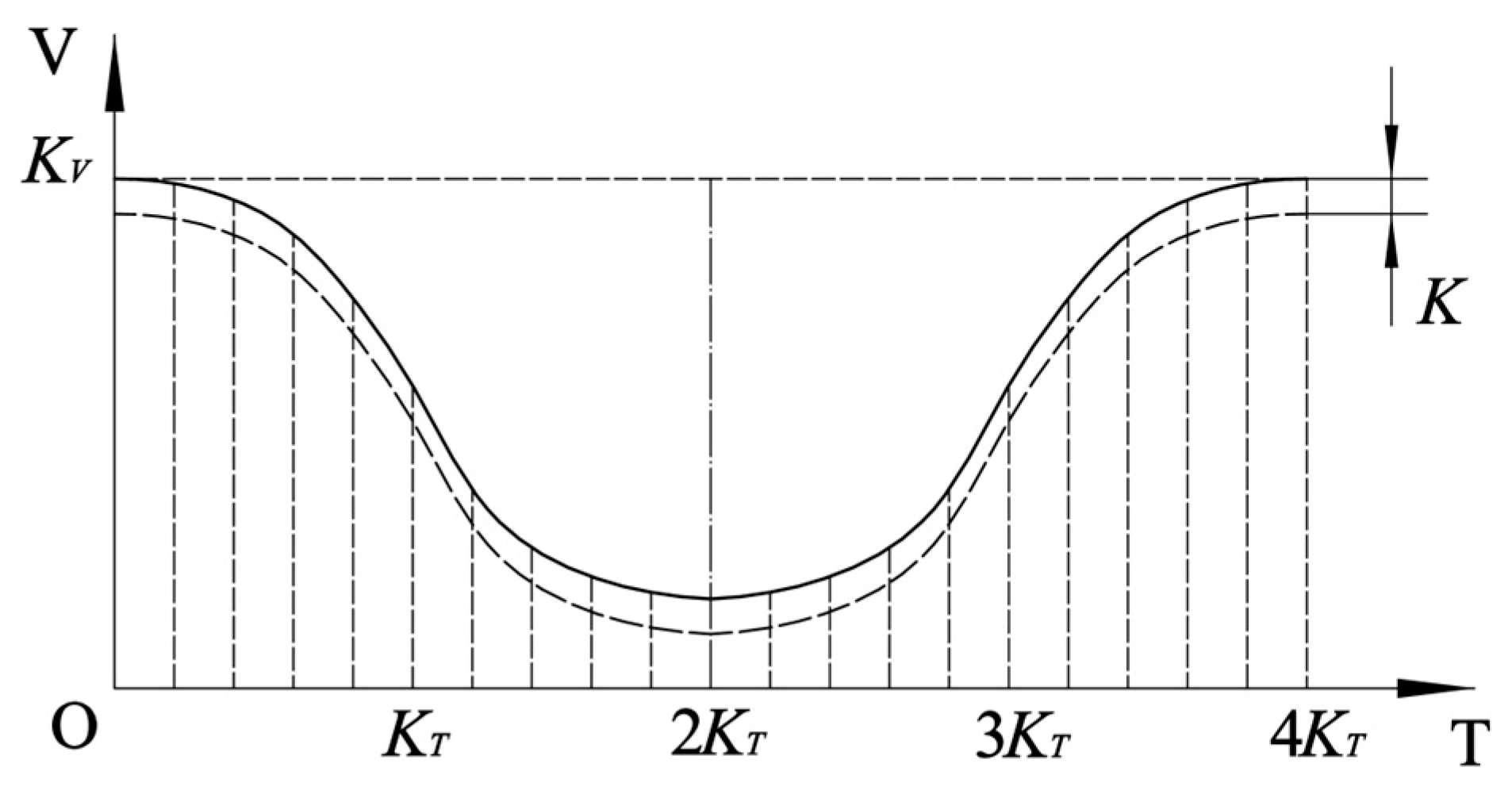
As shown by the solid line in
Figure 8, the sigmoid deformation curve includes the deceleration stage in the first half and the acceleration stage in the second half. A smooth and stable variable speed can be achieved by using the sigmoid deformation curve for interpolation in the variable region. Equation (22) is the mathematical expression of the sigmoid deformation curve.
where
is time adjustment parameter that controls the range of the independent variable interval, which is equal to 0.25 times the variable speed time;
is the velocity adjustment parameter that controls the range of the dependent variable interval, which is equal to the initial velocity of the variable speed stage;
is acceleration adjustment parameter that controls the slope of the sigmoid deformation curve, which is solved by Equations (24) and (25); The constant term
represents the difference between the actual velocity and the initial and final velocity of the sigmoid deformation curve.
The following displacement curve expression is obtained by integrating Equation (22) within the interval
:
Substitute the interval length
of the variable speed region into Equation (22) to simplify the monadic equation of acceleration adjustment parameter
:
Use the numerical method to calculate Equation (24) and obtain the initial acceleration adjustment parameter
. Due to the upper limit of the driving axis acceleration of the machine tool being
, it can be inferred from the derivative of Equation (22) that the slope of the sigmoid deformation curve is the highest at
and
, which the maximum acceleration value during the variable speed stage. Substitute
and
into the derivative expression of Equation (22), and use the upper limit of acceleration
to constrain
:
If the initial satisfies Equation (25), substitute it as the final acceleration adjustment parameter into Equations (22) and (23) to obtain the expressions of the sigmoid deformation curve and displacement curve. If the initial does not satisfy Equation (25), increase the variable speed time to reduce the maximum acceleration during the variable speed stage.
7. Experiment
The cutter position points obtained by the tool path planning algorithm are further processed by the post-processing algorithm to calculate the corresponding displacement data and driving speed data of each axis. Finally, the driving data are integrated into a machining file and imported into the motion control system of the symmetrical XYZ-3RPS double-sided hybrid machine tool. Single-sided machining and double-sided collaborative machining experiments were conducted on nylon material workpieces (350 × 200 × 50) using a 3 mm ball nose end mill, with an axial depth of 2 mm and the same machining tool path. As shown in
Figure 3, the machine tool is divided into left and right sides, and partial double-sided collaborative driving data on the left side are shown in
Table 2 and
Table 3.
x,
y,
z,
d1,
d2,
d3 represent the driving displacement of the six driving screws of the XYZ-3RPS hybrid machine tool on the left side, while
vx,
vy,
vz,
v1,
v2,
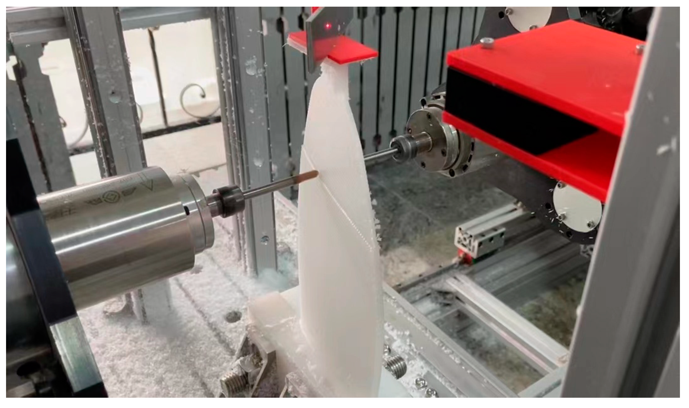
v3 represent the driving speed of the six driving screws of the XYZ-3RPS hybrid machine tool on the left side. The double-sided collaborative machining process of propeller blades is shown in
Figure 9.
With the help of a laser rangefinder and detection board installed on the blade, the deformation and vibration data of single-sided machining on the left side and double-sided collaborative machining are collected and integrated into this experiment. The comparison curves of deformation and vibration during the machining process are shown in
Figure 10 and
Figure 11. The red curve represents the axial deformation of the blade, while the blue curve represents the axial vibration of the blade.
Through the analysis of curve data, the comparison data of evaluation indicators can be obtained as shown in
Table 4. It can be concluded that the deformation range of single-sided machining is between −0.209~0.456 mm, and the deformation range of double-sided collaborative machining is between −0.193~0.138 mm. By comparing the deformation range results, it can be seen that the double-sided collaborative machining method to some extent weakens the local influence of overturning torque and torsional torque on workpiece deformation during single-sided machining. Especially during each cycle of machining back and forth, the problem of machining deformation is effectively improved. However, the uneven force distribution on both sides of the machining area and the deformation resilience can still lead to significant deformation from the perspective of the entire machining process. Therefore, the process parameters of the double-sided collaborative machining method still need to be optimized in subsequent research.
Xp,
PP,
rms, and
CL represent the peak value of vibration, the peak-to-peak value of vibration, the root mean square value of vibration, and margin indicators, respectively. The vibration peak value and peak-to-peak value reflect the amplitude and range of the variation curve. The root mean square value of vibration reflects the strength and stability of the vibration signal. If this indicator abnormally increases, it indicates that there are hidden dangers in the processing process. The margin indicator is the ratio of vibration peak to square root amplitude, reflecting the impact characteristics of the vibration signal. The larger the indicator, the stronger the processing vibration impact. By comparing the evaluation indicators, it can be seen that double-sided collaborative machining has greatly improved the vibration compared to unsupported single-sided machining, indicating that the double-sided collaborative machining method can improve the machining result effectively.
Finally, the quality of the machined blade is evaluated in the experiment by measuring the blade radius, section length under three radii, and surface roughness. Measure the blade radius length R and the section length at 0.2R, 0.5R, and 0.95R using the range finder, and take the average of three times as the final result, as shown in
Table 5. The deviation rate of blade radius is 0.13%, which meets the requirement of ±0.2% for extreme radius tolerance of Class S in ISO 484-2:2015 [
19]. The deviation rates of section length are 0.38%, 0.46%, and 0.35%, respectively, meeting the requirement of +2% for blade section length tolerance of Class S in ISO 484-2:2015 [
19].
The surface roughness of the area at 0.4R of the blade is measured by laser rangefinder. The evaluation length is composed of five sampling lengths of 0.8 mm, and the roughness curves shown in
Figure 12 are obtained by processing the contour curve. The blue color is the roughness curve, and the red color is the arithmetic mean center line. Calculate the arithmetic mean deviation value Ra of the sampling length by Equation (26):
where
m is the number of measuring points within the sampling length, and
hm is the fluctuation value of the distance from a single measuring point to the arithmetic mean center line.
The arithmetic mean deviation Ra of the five sampling lengths is 0.0026 mm, 0.0041 mm, 0.0072 mm, 0.0058 mm, and 0.0037 mm, respectively, and the arithmetic mean deviation Ra of the evaluated length is 0.00468 mm, meeting the requirements of 5 μm for surface roughness arithmetic mean deviation of Class II in ISO 484-2: 2015.


