Article

Mechanical Properties of the Shield Tail Brush and Its Pressure Distribution Acting upon the Segment

1
Department of Geotechnical Engineering, College of Civil Engineering, Tongji University, Shanghai 200092, China
2
Key Laboratory of Geotechnical and Underground Engineering of Ministry of Education, Tongji University, Shanghai 200092, China
*
Author to whom correspondence should be addressed.
Appl. Sci. 2023, 13(11), 6451; https://doi.org/10.3390/app13116451
Submission received: 30 April 2023 / Revised: 15 May 2023 / Accepted: 19 May 2023 / Published: 25 May 2023
(This article belongs to the Special Issue Urban Underground Engineering: Excavation, Monitoring, and Control)

Abstract

:
Shield tunnels are widely used in underground transportation. The shield tail brush is an important component of the shield machine, but also can exert an adverse influence on the segment as it can induce considerable and uneven pressure thereon. Therefore, it is necessary to consider the tail brush pressure in calculations on the segment. However, there are few studies on the calculation method of this pressure. As a consequence, this study carried out laboratory tests on the tail brush, and revealed the two-stage nature of its pressure-compression curve, which can be fitted well by a line together with a polynomial function. In addition, formulas describing the tail brush pressure distribution along the circumference were derived by theoretical analysis. Furthermore, by summarizing the distribution law, simplified formulas for the tail brush pressure acting upon the segment along the circumference and lengthwise due to vertical shield posture adjustment were established. The results can be used in calculations on the segment to improve the segment design and provide guidance for shield tunnel construction.

1. Introduction

Today, congestion of ground transportation in cities is increasing; in such a context, the development and utilization of urban underground space is also increasing and, as a result, large cross-section underpasses have been built. Benefiting from their advantages such as high construction efficiency, safety and reliability, and their low impact on the environment, shield tunnels are widely used by the engineering community [1,2,3], and continue to develop in the direction of large cross-section, deeper burial, higher external water pressure, and more complex geological conditions, making the design and construction of shield tunnels increasingly complex [4,5,6,7,8,9].
At the tail of the shield machine, there are several shield tail brushes arranged between the shield tail shell and the segment (Figure 1). Their main function is to seal the shield tail to ensure that the shield machine can complete the construction safely and successfully. However, negative effects may also arise in some conditions.
According to extensive research, the force upon the tunnel segment induced by tail brushes is considerable. According to the mechanical test and field measurement, the pressure upon the segment would reach the maximum value while the shield tail brush passes through, which is about twice the theoretical earth pressure, and even up to four times more than the theoretical earth pressure in some projects, resulting in a significant effect on the distribution of the segment internal force [11,12,13,14]. The more unfavorable situation is that when the shield adjusts its posture, the shield tail clearance changes, leading to the tail brushes behind the segment compressing the segment unevenly and to a great risk of dislocation, damage, and cracking of the segment [15,16,17,18,19,20] (Figure 2), in turn causing great risk to engineering safety. Therefore, the shield tail brush pressure has gradually attracted more attention from researchers. Qin et al. [15] and Chaipanna et al. [21] took the tail brush in the shield shell into consideration in 3D numerical models to estimate the effect of tail brush extrusion on segments under different shield postures. The results suggest that shield tail brush extrusion would cause extremely uneven pressure on the segment, resulting in a large internal force and displacement of the segment, while the dislocation of the key block usually exceeds the safe limits, and tends to cause cracks and fracturing of the block.
The aforementioned efforts have considerably improved many aspects of our understanding of shield tail brush pressure. However, the existing studies focus on the effects of the tail brush extrusion on segments, but few studies have looked at the mechanical properties of the tail brushes and the method to calculate the magnitude of the tail brush extrusion pressure, which is the key factor in reasonably predicting the extrusion effect. In addition, the relevant research on the properties of the shield tail brushes is mostly limited to the structural design [23], wear resistance [24] and replacement schemes [25,26].
As a remedy for this deficiency, Ye et al. [27], Wei [28], Zhu et al. [29], and Zhong et al. [30] conducted mechanical tests on the shield tail brush. Ye et al. [27] conducted a compression test on the tail brush and in situ monitoring of the pressure acting upon a large shield tunnel, and obtained the characteristics of the load-compression curve, which shows that the tail brush pressure increases linearly with the compression deformation at first, then increases exponentially. In addition, they studied its effect on the segment internal force and cracking by numerical simulation and in situ monitoring, pointing out that the uneven shield tail brush pressure may be the main factor leading to the cracking of a segment.
Wei et al. [28] focused on the sealing performance of the tail brush and studied the deformation of the tail brush under different shield tail clearances and transverse grease pressures. Zhu et al. [29] and Zhong et al. [30], while also focusing on the sealing performance, carried out cyclic loading compression experiments on the tail brush. The results show that the pressure on the tail brush increases slowly at first and then rapidly with the decrease in the tail clearance. Additionally, the cyclic loading will lead to a gradual accumulation of plastic deformation of the tail brush. Further, the relationship between the shield tail gap, tail sealing performance and tail load is established.
It can be concluded that there are few studies on the mechanical properties of the shield tail brush and the method used to calculate its extrusion pressure at present. The above relevant research provides reference for understanding the mechanical properties of the shield tail brush and the research methods of this issue. However, these test results lack further analysis and summary, the mechanical properties of the shield tail brush have yet to be understood adequately, and there has yet to be a convenient and reasonable method established with which to calculate the tail pressure upon the segment; the current study of this pressure mainly relies on field monitoring or assumptions, bringing inconvenience to the segment design. In view of this, a laboratory test was conducted on the shield tail brush, and its mechanical properties and the pressure acting upon the segment were investigated in greater detail, to achieve the calculation method of the tail brush pressure.
Based on the laboratory test on the shield tail brush, Section 2 analyzes and summarizes the law that the pressure of the shield tail brush increases with the compression deformation. In addition, Section 3 derives the compression deformation of brushes at arbitrary positions along the segment periphery by theoretical analysis and combines it with the mechanical property of the brush, so that the computational formula for the tail brush pressure distribution upon the segment is achieved. Ultimately, for ease of application, a simplified formula for the tail brush pressure upon the segment due to vertical adjustment of the shield posture is obtained. The conclusions are drawn in Section 4. The results of this study could provide an experimental case and calculation method for further study on the effect of the tail brush pressure, provide potential theoretical guidance for the segment design and improve the safety of shield tunnel construction in the future.

2. Materials and Methods

To investigate the mechanical properties of the shield tail brush and obtain the data needed for the calculation in Section 3, a compression test on the tail brush was conducted, and the resulting load-compression curve was analyzed in Section 2.2 and Section 2.3 and will convert the load-compression curve to the pressure-compression curve and be fitted with a polynomial, so that the tail brush pressure distribution acting up on the segment could be calculated by using this polynomial and the tail brush compression distribution in subsequent sections.

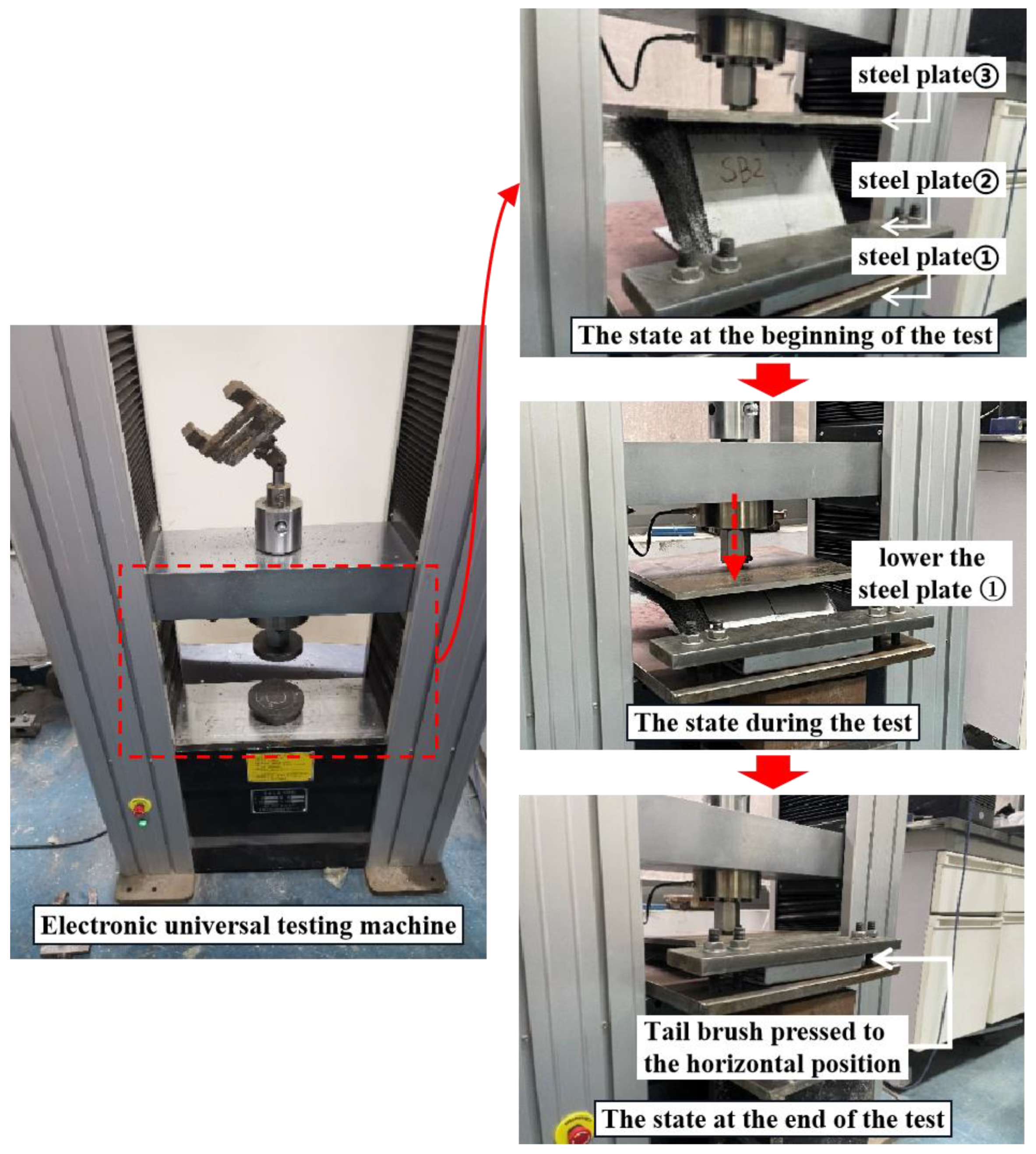
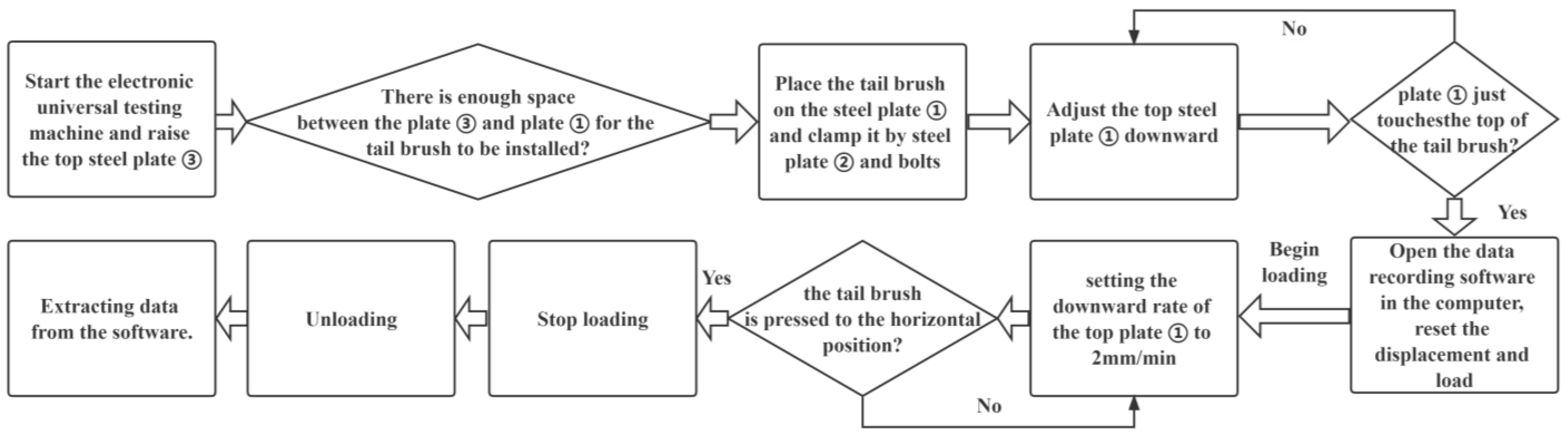
2.1. Compression Test on the Tail Brush

A large-diameter shield tunnel has a segment radius of 7.5 m (Figure 3); the shield tail wire brush used in this tunnel and this laboratory test is shown in Figure 4. The shield tail clearance is 100 mm, and the initial height of the shield tail brush before installation is 190 mm with an initial compression deformation of 90 mm once installed.
Figure 4 shows that the wire brush consists of 11 parts: upper cover, lower cover, pin, front protection plate, rear protection plate, long wire set, broken wire set, inner front plate, inner rear plate, middle plate, wire mesh, and rear reinforcement plate. The thickness of the brush is 32 mm, and the length of the front and rear protection plate is 160 mm. The steel wire is made of ZB202C with a diameter of 0.3 mm. The upper and lower covers are made of SPHC. The spring steel plate is made of 65 Mn, with a hardness HRC value of 43 to 48. The wire mesh is made of SUS201, and the specification is 40 mesh. The covers, spring plates, and wire sets contain a total of six fixed pins; if we use the spin riveting process, the surface is flat and free from burring.
The test was made using the electronic universal testing machine for loading with a steel base plate ① fixed to the base of the machine to place and secure the wire brush, as illustrated in Figure 5.
After the instruments were prepared as described above, the test could be performed as follows (Figure 6):
(1)
Start the electronic universal testing machine and raise the top steel plate ③ to a height sufficient to leave enough space for the wire brush to be installed.
(2)
Place the wire brush on the steel plate ① and clamp it with a steel plate ② and bolts.
(3)
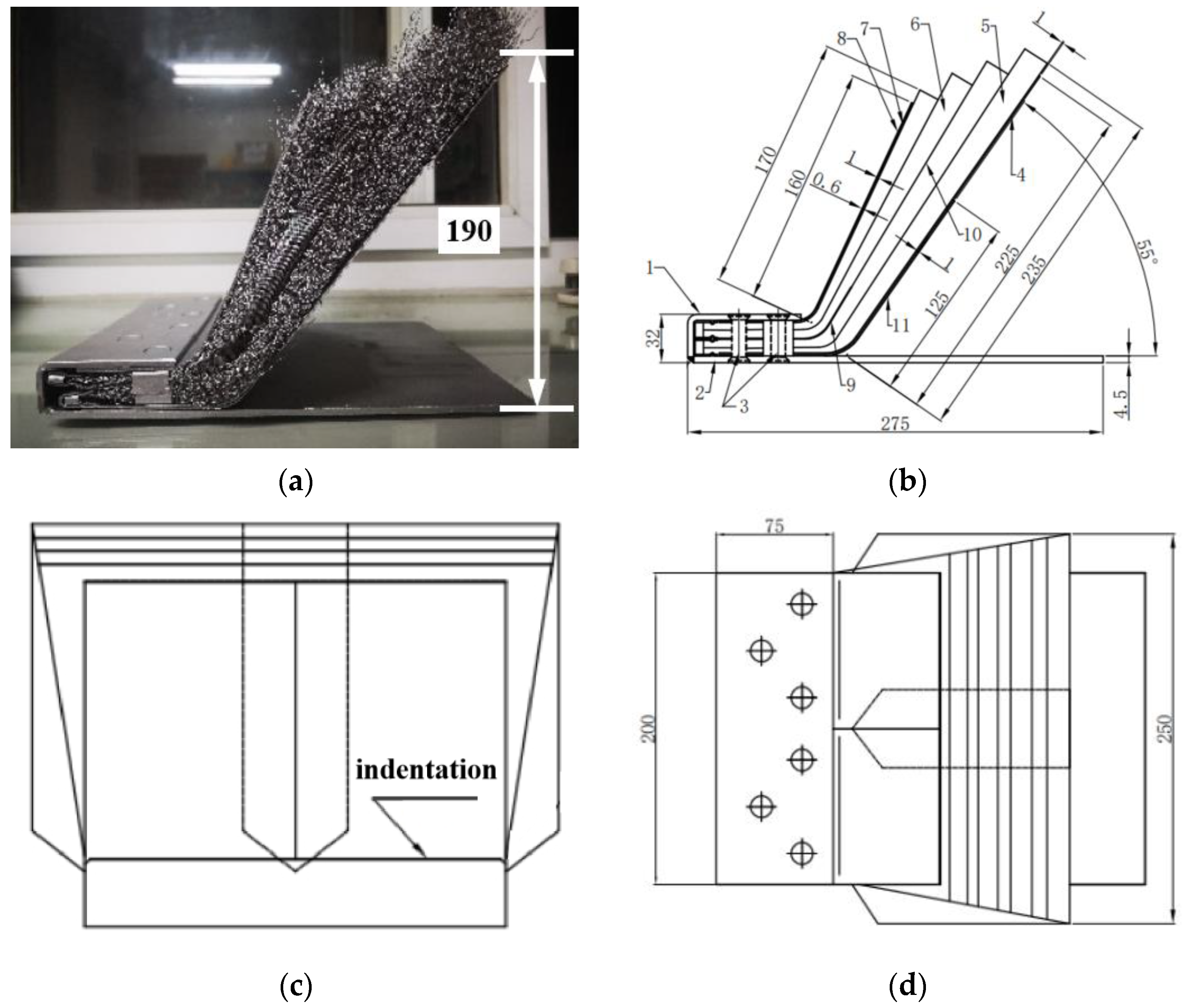
Adjust the top steel plate ① downward until it just touches the top of the tail brush (Figure 5).
(4)
Open the data recording software in the computer, reset the displacement and load; it is then possible to apply the load by setting the downward rate of the top plate ① to 2 mm/min.
(5)
Stop the loading when the shield tail brush is pressed to the horizontal position (Figure 5).
(6)
Unload and extract the displacement and load data from the software.
Figure 6. Flow chart of the test procedure.
Applsci 13 06451 g006

2.2. Mechanical Properties of the Steel Wire Brush

In actual projects, the tunnelling posture of the shield may change continuously to make a turn, tunnelling uphill or downhill; as a result, the shield clearance fluctuates and makes the tail brush inevitably experience multiple loading and unloading. Considering this case, three load–unload cycles were applied to the tail brush.
The load-compression curve of the wire brush is illustrated in Figure 7. It can be seen from the figure that, in the first loading process, the force rapidly rises from 0.1 kN to 2 kN when the displacement reaches about 18 mm, which is due to the bulging-out deformation of the front plate and its separation from the wire; it is then squeezed to a fracture (Figure 7). This situation leads to a rapid increase in the load acting on the segment by the tail brush; hence, attention should be drawn to it during construction. Thereafter, the front protection plate returns to the state of deformation in concert with the wire mesh, and the load reverts to a steady increase with the increase in the compression deformation. In the second and third compression deformation processes, the squeezing of the front plate is still apparent.
From an overall view, the load-compression curve can be divided into two stages: when the compression deformation of the tail brush is less than 78 mm, the load can be approximated as linear with the deformation under the premise of ignoring the deformation and fracture of the front plate resulting from the squeezing; when the deformation is greater than 78 mm, the load will show a non-linear trend with the growth of the deformation until the compression deformation reaches the limit value of 140 mm, at which time the load is about 8.6 kN, and the stress will increase rapidly under continued loading.
In addition, as the number of loading cycles applied on the tail brush increases, its maximum compression deformation will gradually decrease, to about 140 mm in the first compression cycle, and decrease to 130 mm in the second compression deformation, then continue to decrease to 121 mm in the third. During construction, as the tail brush is compressed repeatedly and risks being worn out, irrecoverable plastic deformation will occur, which will lead to a gradual reduction in its sealing performance.

2.3. Pressure upon the Segment Caused by the Tail Brush Compression

As the contact area between the tail brush and the segment is 0.02475 m2, the load-compression curve at the first compression can be converted into a pressure-compression curve (Figure 8). Furthermore, based on the two-stage characteristic of the curve analyzed above, it can be fitted with a linear function and a polynomial function.
When the total compression deformation d (mm) is between 0 and 78 mm, the behavior is linear and the pressure p   kPa acting on the segment by the shield tail brush can be given by:
p = 0.4289 d ;
when the total compression deformation is greater than 78 mm, it is entering the non-linear phase, and the polynomial function (2) can fit the curve, with R2 0.9978.
p = 8 e 5 d 4 0.0332 d 3 + 5.0804 d 2 344.02 d + 8714.7 ,

3. Results

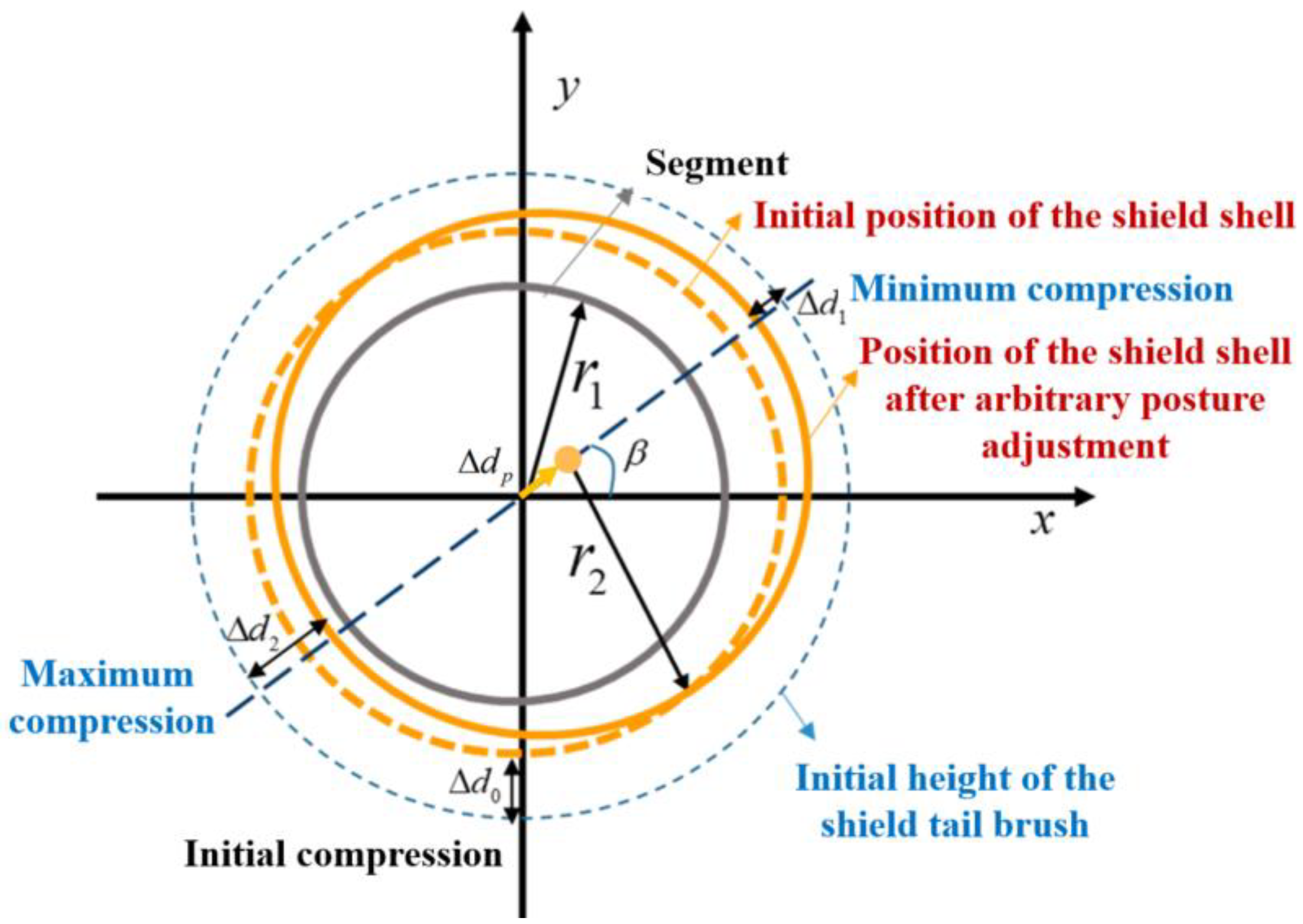
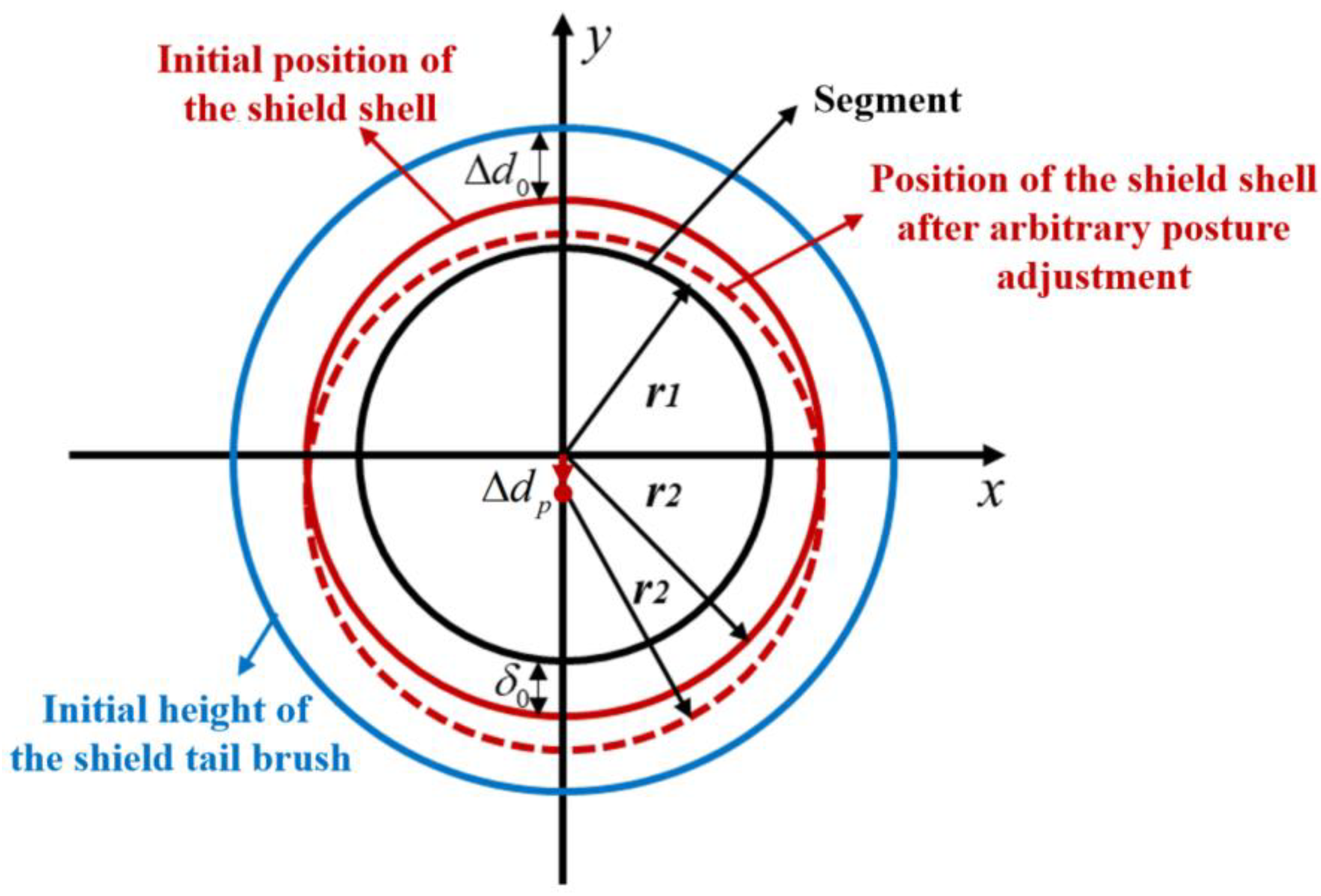
3.1. Geometric Analysis of the Tail Brush Compression and the Resulting Pressure

As shown in Figure 3 and Figure 4, the difference between the initial height of the shield tail brush and the shield tail clearance results in a 90 mm initial compression deformation of the tail brush at the initial installation, which would exert a non-negligible pressure on the segment. In addition, when the position of the shield shell is shifted, the compression deformation of the tail brush around the segment and the corresponding pressure upon the segment will change to be uneven accordingly. To calculate the distribution of this pressure, it is first necessary to calculate the compression deformation distribution of the tail brush around the segment.
We established a coordinate system with the shield shell center as the origin when it was at the design position, and assumed that the center of the shield shell was shifted in the direction of the angle β with the horizontal direction under arbitrary posture adjustment; thus, the diagram representing the relative positions of the shield shell, the tail brush, and the segment is illustrated in Figure 9.
As shown in Figure 8, Δ d 0 denotes the initial compression deformation of the tail brush, Δ d 1 denotes the maximum compression deformation of the tail brush along the circumference at a given state of the shield posture adjustment, while Δ d 2 denotes the minimum compression deformation; r 1 is the outer diameter of the segment, r 2 is the outer diameter of the shield shell, δ 0 denotes the initial shield tail clearance and β is the angle between the shift direction of the shield shell circle center and the horizontal direction due to posture adjustment.
Under any posture adjustment, there always exists a maximum value and a minimum value for the compression deformation of the tail brush around the segment, both of which vary with the offset of the shield center (Figure 10), and half of the difference between these two values is equal to the offset of the shield center.
In other words, the offset of the shield shell center under any posture adjustment is:
Δ d p = Δ d 1 Δ d 2 2
The coordinates of the center are:
Δ d p c o s β , Δ d p s i n β  
The circle equation for the initial state of the shield shell is:
x 2 2 + y 2 2 = r 2 2  
The circle equation for the shield shell under any posture adjustment is:
x 2 Δ d p c o s β 2 + y 2 Δ d p s i n β 2 = r 2 2  
The circle equation of the outer surface of the segment is:
x 1 2 + y 1 2 = r 1 2  
The clearance between any position on the circumference of the shield shell and the segment is:
δ = r 2 x 1 Δ d p c o s β 2 + y 1 Δ d p s i n β 2  
Consequently, the increment of the tail brush compression deformation at any position on the outer surface of the segment can be described thus:
Δ d = δ 0 r 2 x 1 Δ d p c o s β 2 + y 1 Δ d p s i n β 2  
Combining the tail brush compression deformation (Equation (8)) with the pressure-compression relationship (Equation (2)), the tail brush pressure upon the segment at any position on the segment periphery can be calculated using the following equation:
p =                                                                                                                 0.4289 d                                                     0   mm < d < 78   mm 8 e 5 d 4 0.0332 d 3 + 5.0804 d 2 344.02 d + 8714.7           d > 78   mm d = Δ d + Δ d 0  

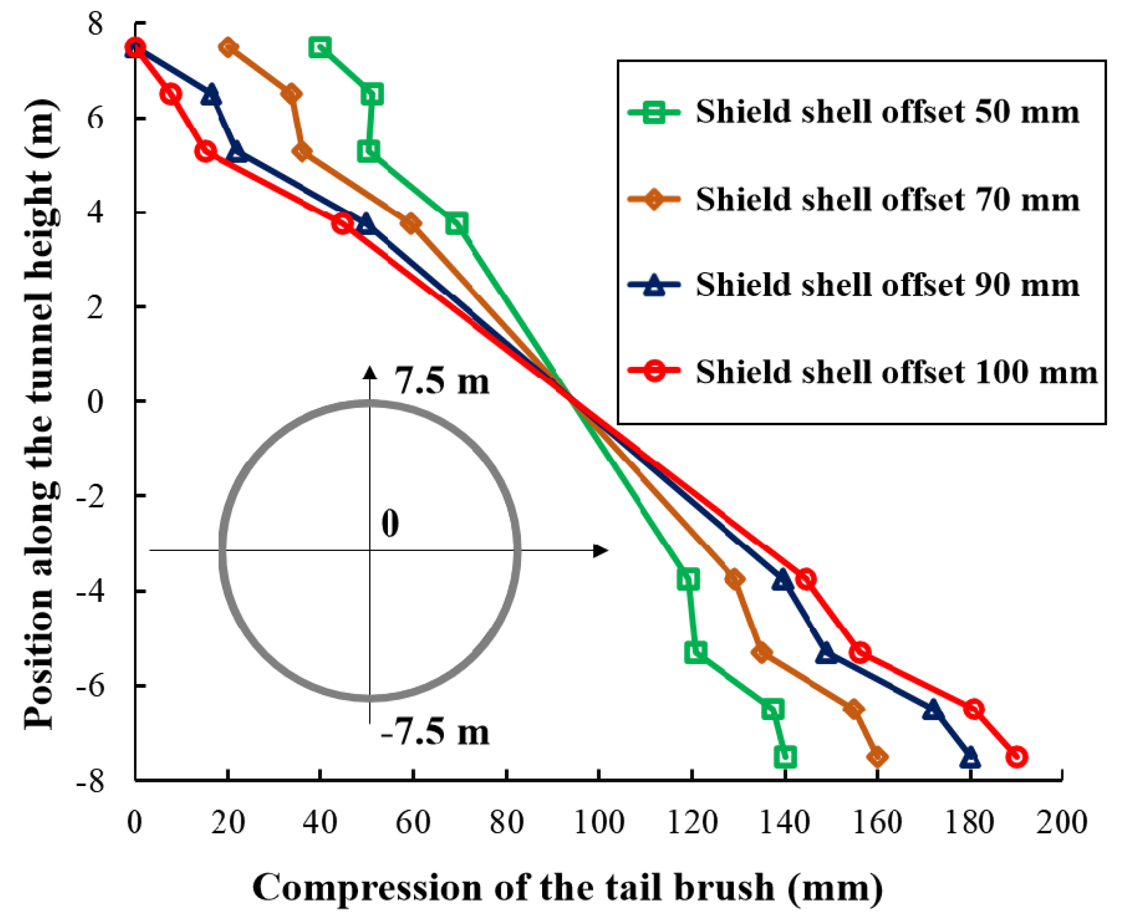
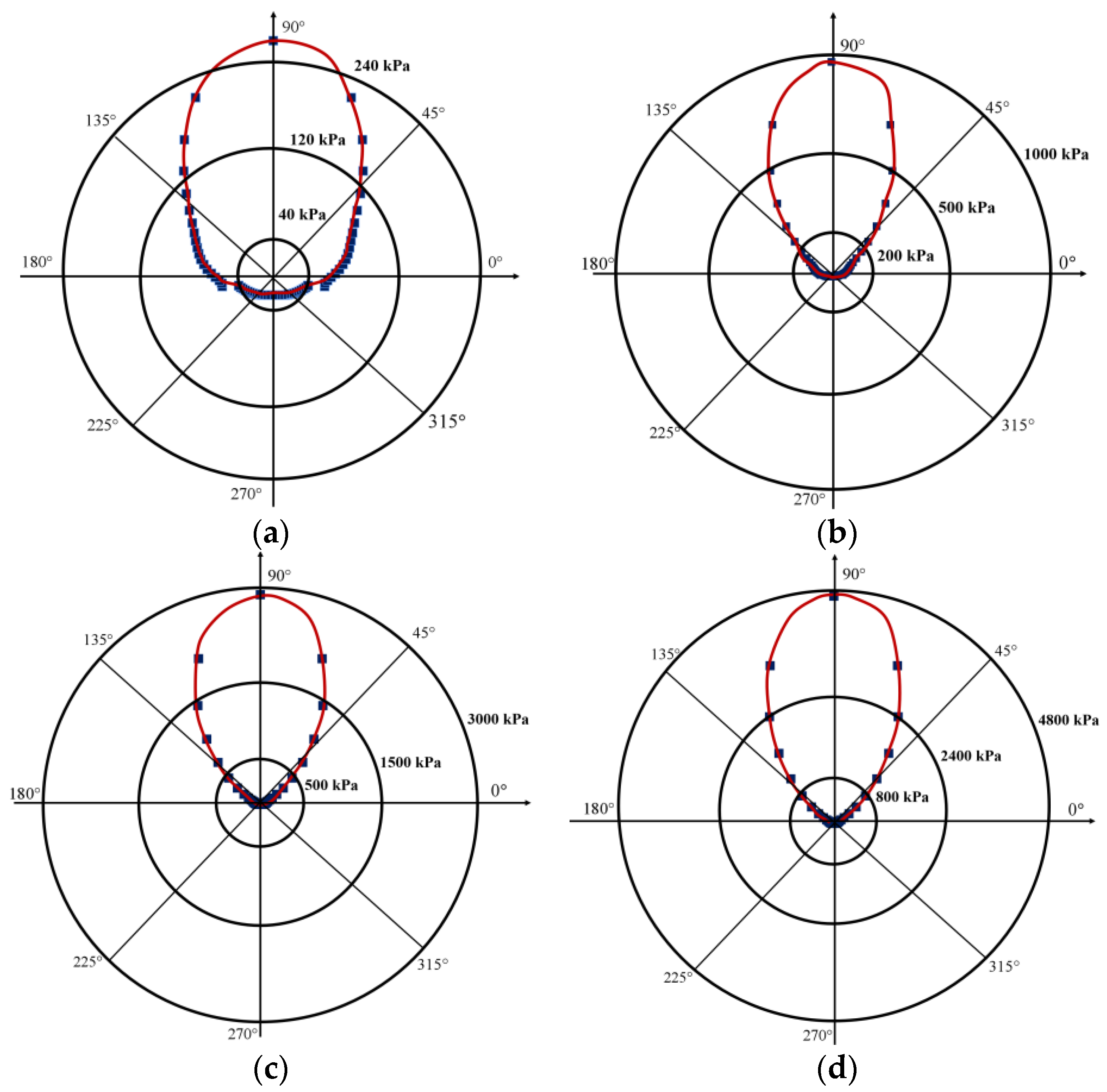
3.2. Pressure Distribution around the Segment Induced by the Tail Brush Due to Vertical Adjustments in the Shield Posture

Taking vertical posture adjustment as an example, when the shield posture adjusts an arbitrary value Δ d p , similar to Figure 10, the two-dimensional model representing the relative positions of the shield shell, tail brush, and the segment is drawn in Figure 11.
From Equation (9), giving the increment of the tail brush compression deformation under arbitrary posture adjustment, and Figure 11, the equation for the tail brush compression deformation increment when the shield posture adjusts in the vertical direction can be obtained as:
Δ d = δ 0 ( r 2 x 1 2 + y 1 Δ d p 2  
By setting the shield shell movement to 50 mm, 70 mm, 90 mm, and 100 mm, respectively, the compression deformation of the tail brush at any position around the segment was obtained according to Equation (11) and has been plotted in Figure 12. When the shield moves downward in the vertical direction, the compression deformation of the tail brush at the tunnel arch bottom is the largest while it is the smallest at the crown of the arch; it is worth noting that the distribution of the compression deformation varies approximately linearly in the direction of the tunnel height.
Combining Figure 12 and Equation (10), we obtained the distribution of the tail brush pressure around the segment under different vertical posture adjustments (Figure 13). When the shield posture is adjusted downward, the distribution of the pressure induced by the tail brush is extremely uneven along the circumference of the segment, and the pressure at the top of the segment is much larger than that at the bottom due to the distribution of the tail brush compression deformation (shown above). With the increase in the shield posture adjustment, the maximum compression deformation at the top is increased correspondingly, causing the segment to be subjected to increasing pressure; furthermore, the distribution of pressure around the segment circumference becomes more uneven.
As mentioned above, the tail brush has an initial compression deformation of 90 mm. With the adjustment in the shield posture, when the maximum compression deformation is 140 mm at the arch crown, the minimum compression deformation will be 40 mm at the arch bottom; as illustrated in Figure 12, the maximum pressure will be 300.91 kPa at the crown in this case. When the maximum compression deformation is 160 mm at the crown, the minimum compression deformation will be 20 mm at the arch bottom, and the maximum pressure will be 1104.99 kPa at the crown. When the maximum compression deformation is 180 mm at the crown, the minimum compression deformation will be 10 mm at the arch bottom, and the maximum pressure will reach 3263.08 kPa at the crown. When the maximum compression deformation is 190 mm at the crown, the minimum compression deformation will also be 0 mm at the arch bottom and the maximum pressure will further increase to 4629.22 kPa at the crown.
Meanwhile, the variation curve in the maximum tail brush pressure together with the maximum compression deformation was plotted in Figure 14. This shows rapid non-linear growth in the maximum pressure with the increase in the maximum compression deformation of the shield tail brush. Therefore, attention should be paid to the control of the shield posture in case the adjustment to the posture is so excessive that the pressure acting on the segment increases rapidly.

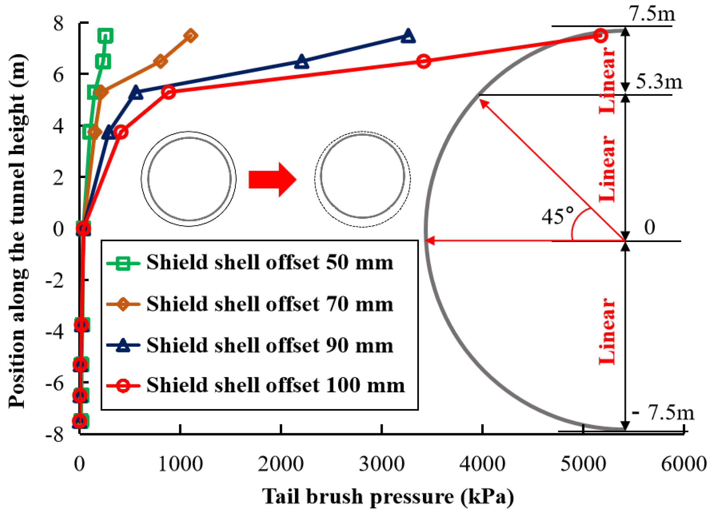
3.3. A Simplified Formula for the Tail Brush Pressure upon the Segment Due to Vertical Adjustment of the Shield Posture

As shown in Figure 13 and described above, when the shield adjusts the posture vertically, the pressure acting upon the segment induced by the tail brush distributes extremely unevenly. As a result, a complete picture of the pressure distribution requires the pressure at many different heights around the segment to be calculated. However, if the pressure at several heights under each shield posture adjustment condition needs to be calculated by using Equations (10) and (11) in tandem, the process is cumbersome.
To facilitate the calculation, the distribution of the tail brush pressure upon the segment was explored and a simplified formula for the pressure was proposed.
In the previous chapter, the tail brush pressure distribution around the segment was calculated and plotted in Figure 13. For further analysis, these pressure distributions along the height of the tunnel were plotted in Figure 15. It is apparent that if the center of the tunnel is taken as the origin, the distribution curve of the pressure can be divided into three sections along the height of the tunnel:
(1)
From the bottom of the tunnel (−7.5 m) to the circle (0 m), the pressure increases linearly with the tunnel height, and the increments are very small.
(2)
From the center (0 m) to 45° from the horizontal (5.3 m), the pressure increases approximately linearly with the tunnel height.
(3)
From 45° from the horizontal (5.3 m) to the top of the tunnel (7.5 m), the pressure increases almost linearly with the tunnel height, but the difference from the first section is that the pressure increases sharply in this section.
It can be assumed that the shield posture is adjusted straight up to an angle of θ ; the relative positions between the components of the tunnel were drawn in Figure 16. The gap between the shield shell and the segment at the top of the tunnel is reduced, while that at the bottom of the tunnel is increased; correspondingly, the compression deformation of the shield tail brush at the top will increase, while that at the bottom will reduce.
A large diameter shield machine in Shenzhen, China, was equipped with five shield tail brushes at the shield tail; it is quite clear in Figure 16 that the compression deformation thereof will be different when the shield posture is adjusted, and the compression deformation along the direction of the shield advancing would gradually decrease at the top of the tunnel along the direction of the shield advance, while it would increase at the bottom.
From the geometric relationship, the compression deformation of each tail brush at the vault can be found as:
d t n = l 2 n 1 t θ + Δ d 0   n = 1 , 2 , 3 , 4 , 5  
where n denotes the number of the brush; d t n denotes the total compression deformation of the n th brush at the top of the tunnel; Δ d 0 is the initial compression deformation of the brush, which is 90 mm in this project; l denotes the length of the shield machine; t is the shield tail clearance at each shield tail brush (0.5 m herein); θ is the posture angle of the shield posture in the vertical direction.
Similarly, the compression deformation of each shield tail brush at the bottom of the tunnel is:
d b n = Δ d 0 l 2 n 1 t θ   n = 1 , 2 , 3 , 4 , 5  
where d b n denotes the compression deformation of the n th shield tail brush at the bottom of the tunnel.
It has been concluded from Figure 15 and the beginning of this section that when the shield posture is adjusted vertically, the pressure acting upon the segment induced by the tail brush varies approximately linearly in the direction of the tunnel height in each of the three sections; therefore, if we take a straight line to represent the shield tail brush compression deformation distribution along the height direction, then its slope is:
d δ n = d t n d b n 15 = θ l 2 n 1 t 15 n = 1 , 2 , 3 , 4 , 5  
Consequently, the compression deformation of the tail brush at the height of the tunnel circle center can be found to be:
d o n = d b n + 7.5 α δ n = Δ d 0   n = 1 , 2 , 3 , 4 , 5  
The compression deformation of the tail brush at a position of 45° from the horizontal is:
d s n = δ o n + 5.3 α δ n = Δ d 0 + 5.3 θ l 2 n 1 t 15   n = 1 , 2 , 3 , 4 , 5  
After finding the compression deformation of the tail brush at the above four segmental points on the pressure curve, we can find the shield tail brush pressure at each segmental point by the fitting (Equation (10)). It should be noted that these four pressures are p b n , p o n , p s n , and p t n , respectively, i.e., the pressure at the bottom, circle center, 45° from the horizontal, and the top of the tunnel. The pressure is distributed in three stages in the height direction, and the slope of each stage is given by:
α 1 n = p o n p b n 7.5 n = 1 , 2 , 3 , 4 , 5  
α 2 n = p s n p o n 5.3 n = 1 , 2 , 3 , 4 , 5  
α 3 n = p t n p s n 2.2 n = 1 , 2 , 3 , 4 , 5  
where α 1 n , α 2 n , and α 3 n represent the slope of the pressure induced by the nth tail brush along the tunnel height direction of the first, second, and third stages, respectively.
Eventually, the distribution of the pressure induced by the shield tail brush along the height direction for any shield tail can be summarized using the following model:
p h n = p b n + h 7.5 α 1 n ,   7.5   m h 0   m           p o n + h · α 2 n ,                                               0   m < h < 5.3   m     p s n + h 5.3 α 3 n ,                 5.3   m h 7.5   m n = 1 , 2 , 3 , 4 , 5
where h represents the height from the circle center of the tunnel.
By virtue of this model combined with the equation of the pressure-compression relationship (Equation (10)), the three-dimensional spatial distribution of the pressure induced by each shield tail brush of a shield can be obtained more easily by just knowing the angle of the attitude adjustment of the shield machine.

4. Conclusions

Laboratory tests and theoretical calculations on the mechanical properties of the tail brush and its pressure acting upon the shield tunnel segment during the shield posture adjustment were conducted in this study. The distribution of the brush-induced pressure was analyzed, and the model of the pressure distribution along the tunnel height due to vertical adjustment of the shield posture was proposed; the main conclusions are drawn as follows:
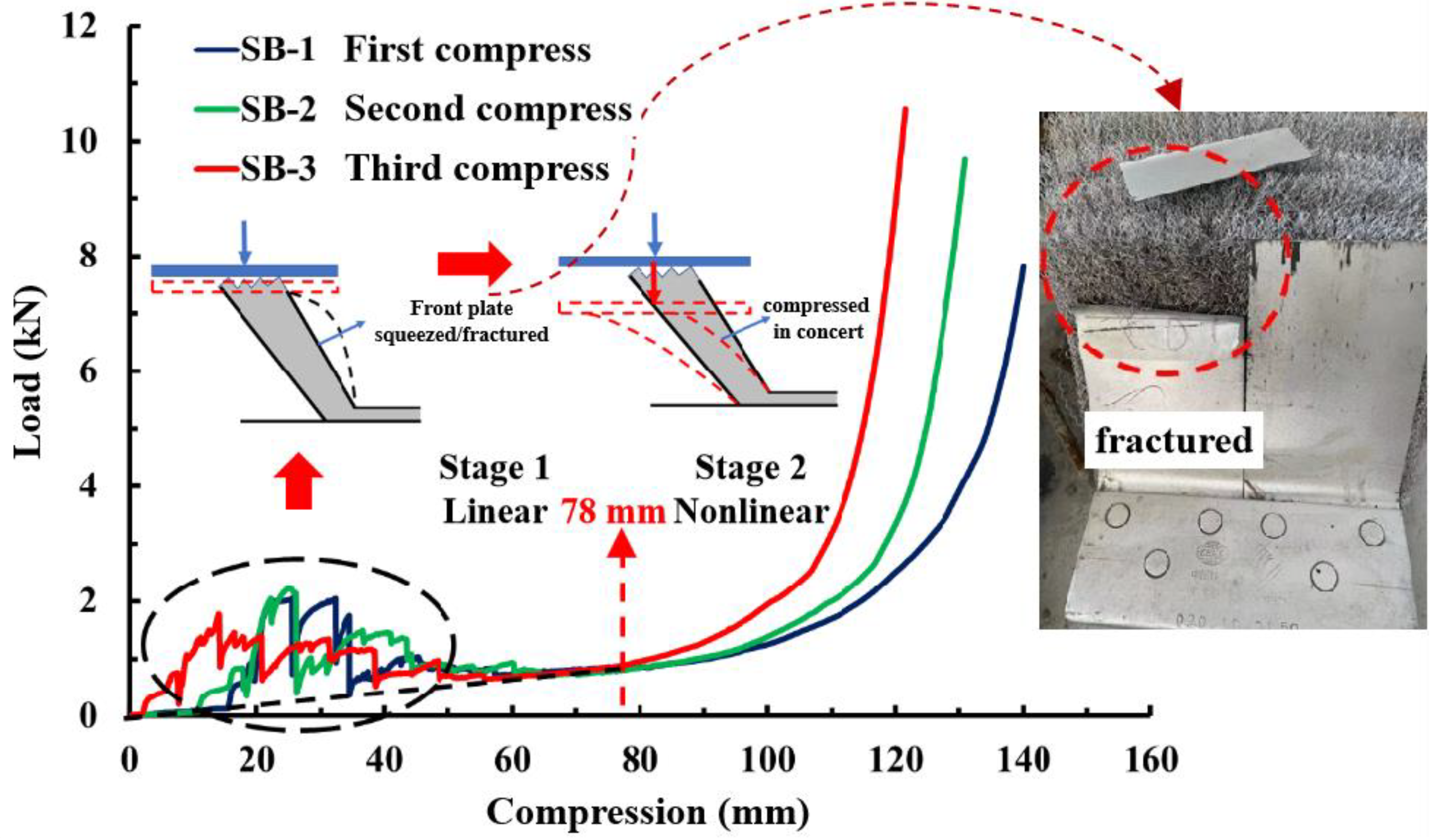
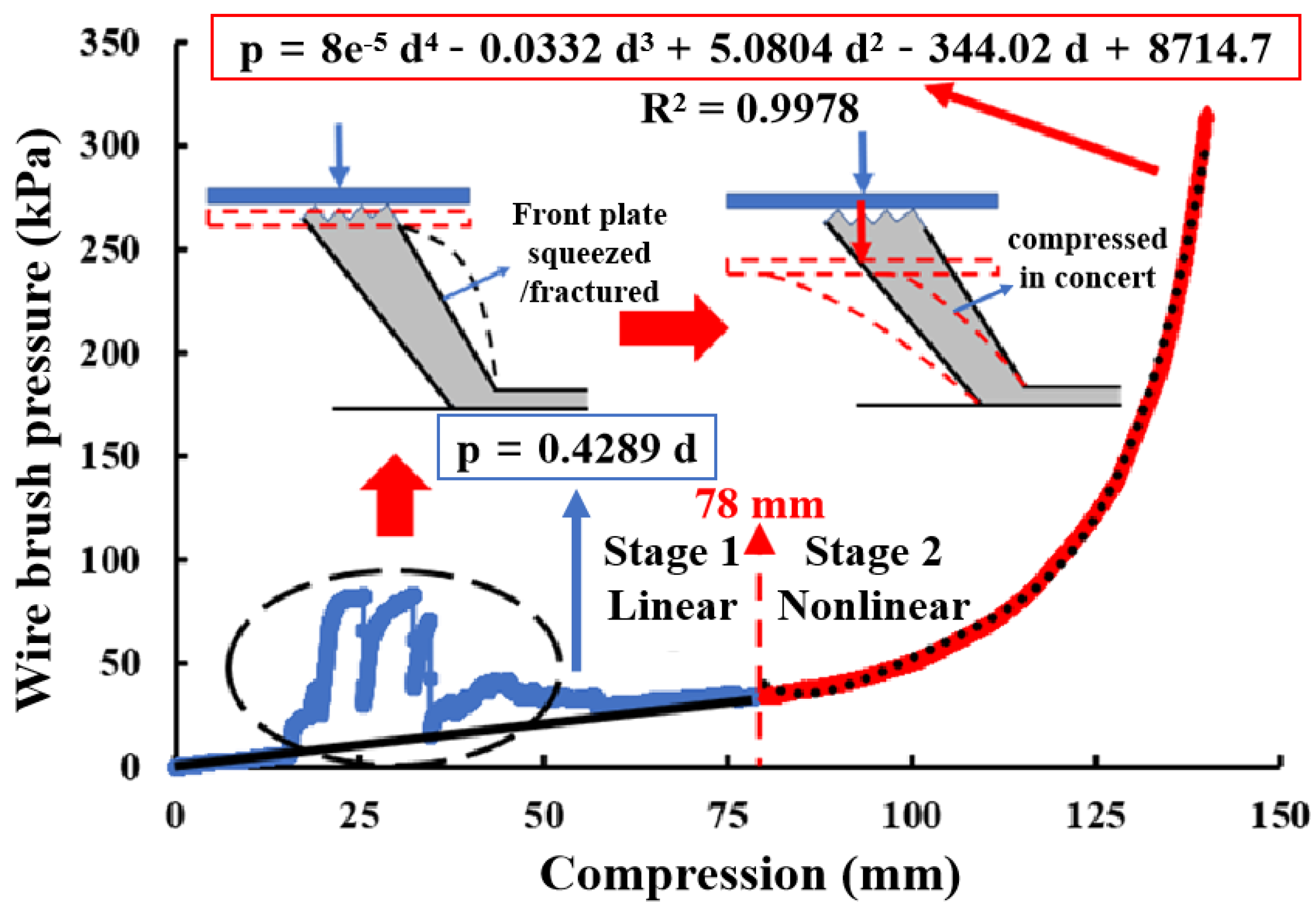
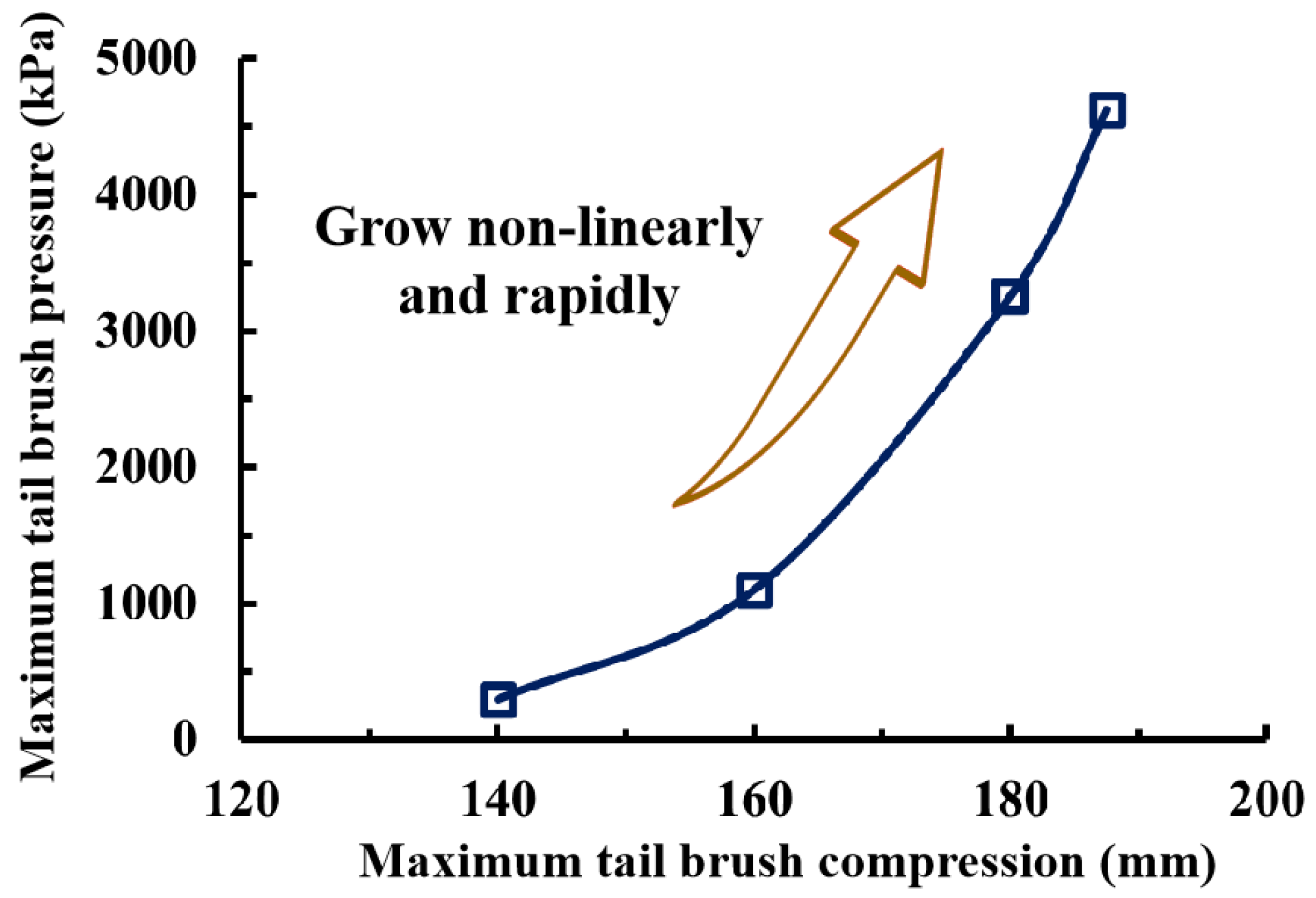
  • The load-compression curve obtained from the laboratory tests showed that the tail brush has a two-stage compressive nature, i.e., the linear stage and the non-linear stage. A line together with a polynomial function could fit the curve well, facilitating the subsequent calculation of the tail brush pressure around the segment circumference.
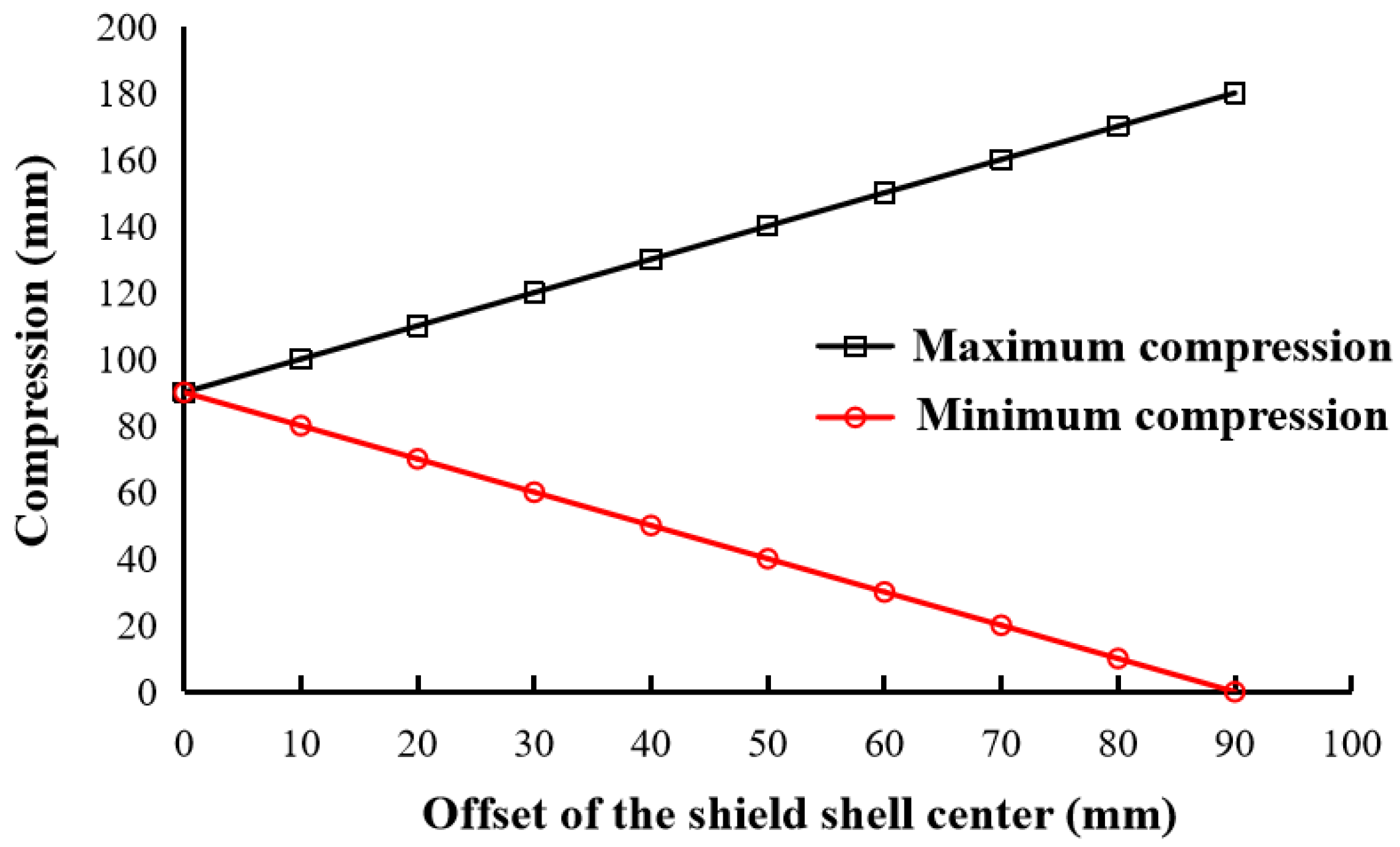
  • Through geometric analysis of the shield shell, tail brush and segment, a formula for the tail brush compression deformation and the corresponding pressure distribution along the segment circumference under arbitrary shield posture adjustment was obtained. The pressure induced by the tail brush under vertical posture adjustment was analyzed as an example. The result shows that, along the tunnel height, the compression deformation of the tail brush varies approximately linearly; with the increase in the posture adjustment, the distribution of the pressure becomes more uneven along the circumference and the maximum pressure increases significantly.
  • For ease of application, the distribution of the tail brush pressure upon the segment under vertical posture adjustment was studied: the distribution of this pressure along the tunnel height presents a three-fold linear form; according to this characteristic, a simplified formula was proposed and based on this formula, the distribution of the pressure could be calculated.
Today, with the rapid development in underground transportation, the shield tunnel is widely used and faced with increasingly complex challenges, and calls for higher quality and safety requirements. As numerous studies have found, the tail brush extrusion could cause significant harm to the segment; it is necessary to consider the shield tail brush pressure in the calculations about the segment. In this case, Equations (9) and (10) or (10) and (20) based on the experiment are significant and convenient to be used in relevant calculations.
However, the research in this article also has certain limitations, such as the fact that this paper focuses on the mechanical properties of the shield tail brush, and the regularity and calculation method of the pressure distribution acting upon the segment, but has not applied it in the calculations about the segment yet. In the future, the conclusions found by this paper can be used to investigate the effect of tail brush extrusion on the segment via calculations with a reasonable and experiment-based tail brush pressure value, to improve the segment design, and to determine the allowed distance of the shield posture adjustment during tunneling. Furthermore, the sealing performance is the key performance of the shield tail brush, and individual studies have paid attention to the relationship between the compression load of the tail brush and its sealing performance. Future studies could further explore this topic.

Author Contributions

Conceptualization, W.D. and Y.Q. (Yafei Qiao); methodology, X.C.; software, X.C.; validation, W.D., Y.Q. (Yafei Qiao) and X.C.; formal analysis, X.C. and Y.Q. (Yanling Qiu); investigation, X.C.; resources, W.D., Y.Q. (Yafei Qiao) and X.C.; data curation, X.C. and Y.Q. (Yanling Qiu); writing—original draft preparation, Y.Q. (Yanling Qiu); writing—review and editing, X.C., Y.Q. (Yafei Qiao) and W.D.; visualization, X.C. and Y.Q. (Yanling Qiu); supervision, W.D. and Y.Q. (Yafei Qiao); project administration, W.D.; funding acquisition, W.D. and Y.Q. (Yafei Qiao). All authors have read and agreed to the published version of the manuscript.

Funding

This research was funded by the National Natural Science Foundation of China, grant number 51978515 and 52090083. And the China Railway Southern Investment Group Co. Ltd. (Project No.ZTNF-2020-1).

Institutional Review Board Statement

Not applicable.

Informed Consent Statement

Not applicable.

Data Availability Statement

Not applicable.

Acknowledgments

The authors would like to acknowledge the managers of the Mawan undercrossing sea tunnel and Shenzhen Line 11 tunnel for their help with this study. The authors wish to express their gratitude to the reviewers for their valuable comments and suggestions.

Conflicts of Interest

The authors declare no conflict of interest.

References

  1. Gong, C.J.; Ding, W.Q.; Mosalam, K.M.; Gunay, S.; Soga, K. Comparison of the structural behavior of reinforced concrete and steel fiber reinforced concrete tunnel segmental joints. Tunn. Undergr. Space Technol. 2017, 68, 38–57. [Google Scholar] [CrossRef]
  2. Li, P.; Zou, H.; Wang, F.; Xiong, H. An analytical mechanism of limit support pressure on cutting face for deep tunnels in the sand. Comput. Geotechnol. 2020, 119, 103372. [Google Scholar] [CrossRef]
  3. Ding, W.Q.; Chen, X.Q.; Jin, Y.L.; Qiao, Y.F. Flexural behavior of segmental joint containing double rows of bolts: Experiment and simulation. Tunn. Undergr. Space Technol. 2021, 112, 103940. [Google Scholar] [CrossRef]
  4. Hou, Y.; Fang, Q.; Zhang, D.; Wong, L.N.Y. Excavation failure due to pipeline damage during shallow tunnelling in soft ground. Tunn. Undergr. Space Technol. 2015, 46, 76–84. [Google Scholar] [CrossRef]
  5. Cao, L.; Fang, Q.; Zhang, D.; Chen, T. Subway station construction using combined shield and shallow tunnelling method: Case study of Gaojiayuan station in Beijing. Tunn. Undergr. Space Technol. 2018, 82, 627–635. [Google Scholar] [CrossRef]
  6. Zhang, W.G.; Han, L.; Gu, X.; Wang, L.; Chen, F.Y.; Liu, H.L. Tunneling and deep excavations in spatially variable soil and rock masses: A short review. Undergr. Space 2022, 7, 380–407. [Google Scholar] [CrossRef]
  7. Ding, W.Q.; Wang, Q.S.; Qiao, Y.F.; Jin, Y.L. Experimental investigation on waterproofing performance of segmental joint with double gaskets for shield tunnel. Undergr. Space 2022, 7, 898–910. [Google Scholar] [CrossRef]
  8. Li, J.Y.; Fang, Q.; Liu, X.; Du, J.M.; Wang, G.; Wang, J. Mechanical Behaviors of Existing Large-Diameter Tunnel Induced by Horseshoe-Shaped Undercrossing Twin Tunnels in Gravel. Appl. Sci. 2022, 12, 7344. [Google Scholar] [CrossRef]
  9. Zheng, H.; Li, P.; Ma, G.; Zhang, Q. Experimental investigation of mechanical characteristics for linings of twins tunnels with asymmetric cross-section. Tunn. Undergr. Space Technol. 2022, 119, 104209. [Google Scholar] [CrossRef]
  10. Han, L.; Ye, G.; Chen, J.; Xia, X.; Wang, J. Pressures on the lining of a large shield tunnel with a small overburden: A case study. Tunn. Undergr. Space Technol. 2017, 64, 1–9. [Google Scholar] [CrossRef]
  11. Koyama, Y. Present status and technology of shield tunneling method in Japan. Tunn. Undergr. Space Technol. 2003, 18, 145–159. [Google Scholar] [CrossRef]
  12. Li, X.; Zhou, S.; Wang, P.; Li, X. Study of distribution law of earth pressure acting on shield tunnel lining based on in-situ data. Rock Soil Mech. 2014, 35, 453–459. [Google Scholar]
  13. Han, L.; Ye, G.L.; Wang, J.H.; Huang, Z.H. In-situ monitoring of earth pressures upon large shield tunnel with small overburden. In Geotechnical Aspects of Underground Construction in Soft Ground, Proceedings of the 8th International Symposium on Geotechnical Aspects of Underground Construction in Soft Ground (IS-Seoul), Seoul, Republic of Korea, 25–27 August 2014; Yoo, C., Park, S.W., Kim, B., Ban, H., Eds.; CRC Press: Boca Raton, FL, USA, 2014; pp. 315–320. [Google Scholar]
  14. Mashimo, H.; Ishimura, T. Evaluation of the load on shield tunnel lining in gravel. Tunn. Undergr. Space Technol. 2003, 18, 233–241. [Google Scholar] [CrossRef]
  15. Qin, J.; Zhu, W.; Chen, J. Study of Dislocation of Duct Pieces and Crack Problems Caused by Shield Attitude Control. Constr. Technol. 2004, 33, 25–27. [Google Scholar]
  16. Mo, H.H.; Chen, J.S. Study on inner force and dislocation of segments caused by shield machine attitude. Tunn. Undergr. Space Technol. 2008, 23, 281–291. [Google Scholar] [CrossRef]
  17. Ishimura, T.; Mashimo, H.; Morimoto, S. Influence of construction load for segmental lining by result of in-situ measurement and numerical analysis. In Underground—The Way to the Future, Proceedings of the World Tunnel Congress (WTC) and the 39th General Assembly of the International-Tunnelling-and-Underground-Space-Association (ITA), Geneva, Switzerland, 31 May–7 June 2013; Anagnostou, G., Ehrbar, H., Eds.; CRC Press: Boca Raton, FL, USA, 2013; pp. 2372–2379. [Google Scholar]
  18. Li, B.; Yan, Q. Study on mechanical behavior of shield segment under shield tail compression during construction. Mod. Tunn. Technol. 2019, 56, 409–417. [Google Scholar]
  19. Ye, G.; Wang, J.; Wang, J.; Qiao, B. Field Monitoring Study on construction load of oversized section shield tunnel segments. Mod. Tunn. Technol. 2010, 47, 85–89. [Google Scholar]
  20. Liu, F.Y.; Ding, W.Q.; Qiao, Y.F. Experimental investigation on the tensile behavior of hybrid steel-PVA fiber reinforced concrete containing fly ash and slag powder. Constr. Build. Mater. 2020, 241, 118000. [Google Scholar] [CrossRef]
  21. Chaipanna, P.; Jongpradist, P. 3D response analysis of a shield tunnel segmental lining during construction and a parametric study using the ground-spring model. Tunn. Undergr. Space Technol. 2019, 90, 369–382. [Google Scholar] [CrossRef]
  22. Ye, F.; He, C.; Wang, S. Analysis of mechanical characteristic of shield tunnel segments lining and its influence during construction. Rock Soil Mech. 2011, 32, 1801–1807. [Google Scholar]
  23. Yang, M. Research on Design and Replacement Technology of Shield Tail Brush of Shield Machine. Railw. Constr. Technol. 2021, 342, 63–67. [Google Scholar]
  24. Sun, K.; Zheng, K.; Dou, J.; Zhao, W.; Wang, S.; Sun, W.; Wang, L. Simulation analysis of tail brush wear characteristics of shield tail sealing system. Mod. Mach. 2022, 231, 6–10. [Google Scholar]
  25. Xu, C.J.; Liu, Y.K.; Cao, Z.G. Numerical analysis and comparison of soil freezing schemes for replacement of shield tail brush in long-distance tunnel engineering. Eur. J. Environ. Civ. Eng. 2018, 22, s316–s332. [Google Scholar] [CrossRef]
  26. Yang, P.; Zhao, J.L.; Li, L. An artificial freezing technique to facilitate shield tail brush replacement under high pore-water pressure using liquid nitrogen. KSCE J. Civ. Eng. 2021, 25, 1504–1514. [Google Scholar] [CrossRef]
  27. Ye, G.; Han, L.; Yadav, S.K.; Bao, X.; Liao, C. Investigation on the tail brush induced loads upon segmental lining of a shield tunnel with small overburden. Tunn. Undergr. Space Technol. 2020, 97, 103283. [Google Scholar] [CrossRef]
  28. Wei, L. Experimental study on mechanical behavior of wire brushes on shield tail. Tunn. Constr. 2021, 41, 206–211. [Google Scholar]
  29. Zhu, W.; Liu, C.; Zhong, X.; You, Z.; Zhu, N. Research on performance evaluation of shield tail brush based on the tests of compression and grease escape. Chin. J. Geotech. Eng. 2023, 45, 1086–1093. [Google Scholar]
  30. Zhong, X.; Huang, S.; Zhu, W.; Chen, Q.; You, Z. Analysis of sealing performance of shield tail brush based on compression and grease escape test. J. Southwest Jiaotong Univ. 2023, 58, 125–132. [Google Scholar]
Figure 1. Shield tail brushes in an actual project [10].
Applsci 13 06451 g001
Figure 2. Common defects in the segment during shield tunnel construction [22].
Applsci 13 06451 g002
Figure 3. Shield tail structure of a large diameter shield tunnel (mm).
Applsci 13 06451 g003
Figure 4. Photograph and design drawing of the wire brush used in the laboratory test: (a) Photograph (b) Section view of the design drawing; (c) Front view of the design drawing; (d) Top view of the design drawing (mm).
Applsci 13 06451 g004
Figure 5. Test equipment and the scheme and the state of the tail brush at different stages of the test.
Applsci 13 06451 g005
Figure 7. Load-compression curves for the wire brush and the fracture of the front protection plate.
Applsci 13 06451 g007
Figure 8. Pressure-compression curve and the fitting functions for the wire brush.
Applsci 13 06451 g008
Figure 9. The relative positions of the shield shell, tail brush, and the segment under arbitrary posture adjustment.
Applsci 13 06451 g009
Figure 10. Relationship between the maximum and minimum compression deformation of the tail brush and the shield offset.
Applsci 13 06451 g010
Figure 11. The relative positions of the shield shell, the tail brush, and the segment under arbitrary vertical posture adjustment.
Applsci 13 06451 g011
Figure 12. Distribution of the tail brush compression deformation along the tunnel height due to different upward offsets of the shield.
Applsci 13 06451 g012
Figure 13. Distribution of pressure induced by the tail brush along the circumference of the segment under different upward offsets of the shield: (a) When the maximum compression deformation is 140 mm (at the crown) and the minimum compression deformation is 40 mm (at the arch bottom); (b) When the maximum compression deformation is 160 mm (at the crown) and the minimum compression deformation is 20 mm (at the arch bottom); (c) When the maximum compression deformation is 180 mm (at the crown) and the minimum compression deformation is 10 mm (at the arch bottom); (d) When the maximum compression deformation is 190 mm (at the crown) and the minimum compression deformation is 0 mm (at the arch bottom).
Applsci 13 06451 g013
Figure 14. The maximum tail brush pressure under different maximum compression.
Applsci 13 06451 g014
Figure 15. Distribution of the pressure acting upon the segment induced by the tail brush due to different vertical adjustments of the shield posture along the vertical direction.
Applsci 13 06451 g015
Figure 16. Relative positions of the components of the tunnel.
Applsci 13 06451 g016
Disclaimer/Publisher’s Note: The statements, opinions and data contained in all publications are solely those of the individual author(s) and contributor(s) and not of MDPI and/or the editor(s). MDPI and/or the editor(s) disclaim responsibility for any injury to people or property resulting from any ideas, methods, instructions or products referred to in the content.

