Article

Three-Dimensional Numerical Modeling of Artificially Freezing Ground in Metro Station Construction

1
School of Civil Engineering and Architecture, Southwest University of Science and Technology, Mianyang 621010, China
2
School of Civil Engineering and Architecture, Hainan University, Haikou 570228, China
3
College of Civil Engineering and Architecture, Wuyi University, Jiangmen 529020, China
*
Author to whom correspondence should be addressed.
Appl. Sci. 2023, 13(1), 671; https://doi.org/10.3390/app13010671
Submission received: 5 December 2022 / Revised: 21 December 2022 / Accepted: 28 December 2022 / Published: 3 January 2023
(This article belongs to the Special Issue State-of-the-Art Earth Sciences and Geography in China)

Abstract

:
In this study, the engineering background of No. 2 complex connecting passage of Binhu Road Station/Jinhu Square Station of Nanning Metro Line 3 is investigated, where the artificial ground freezing technique is adopted. A three-dimensional finite element model is established to investigate the temperature development of the frozen soil curtain, with a simulation of the dynamic evolution of the frosted soil curtain. The finite element model is validated by comparing the overall trend of the measured temperature value and the resulting temperature value, which are roughly the same. According to the design scheme, the weakest part of the whole frozen soil curtain is the top of the bell mouth where the downhole tunnel intersects the connecting passage. It is recommended to make a row of smaller freezing holes to enhance the freezing effect in this area. The thickness of the frozen soil curtain reached 1.75 m or more, indicating that the whole frozen soil curtain meets the design requirements and shows the right features for excavation construction. After freezing for 40 days, the average thickness of the frozen soil curtain is 2.4 m, indicating that the freezing effect meets the design requirements. The project can be successfully carried out, which suggests that the underneath passage construction is feasible. As a result, the results of the numerical model are applicable for comparable projects using artificially freezing ground in metro station construction.

1. Introduction

A subway connecting passage, also known as the bypass channel or escape channel, is built in the middle of each subway tunnel section (sometimes with a pump house). The shape of the section may be circular, rectangular, or a straight wall arch. The most common form in construction is the straight wall arch, with a wall height of 2.5~3.5 m and a span of 2.0~3.0 m. The construction of the connecting passage is a key aspect of the construction of the subway. It can be constructed by using construction methods such as the ‘open-cut’ method, the ‘undercut’ method, the ‘first open-cut and then undercut’ method, and the ‘pipe jacking’ method. Due to above-ground traffic restrictions, the undercut method is often used. The decision as to which surrounding soil reinforcement method should be chosen is a technical problem that is frequently encountered [1,2,3]. The surrounding soil layer is reinforced by grouting in the tunnel, freezing in the tunnel, deep ground mixing, or rotary jet blasting [4,5,6]. When encountering a water-rich sandy soil layer, grouting in the tunnel is unstable and the quality is not easy to guarantee. Worse still, it is often impossible to carry out ground deep mixing or rotary jet reinforcement due to above-ground traffic restrictions. Therefore, the soil layer around the connecting passage is often reinforced using the ‘freezing in the tunnel’ method [7]. The common construction methods for connecting passages of metro station are summarized in Table 1. Water leakage likely occurs during construction phase of these methods, and the artificial ground freezing technique can be adopted to address this water leakage problem.
Many researchers have studied the soil layer construction methods around connecting passages reinforced by the freezing method and combined these with practical engineering examples and reported much useful experience. Zhang and He [8] used three-dimensional finite element simulation to study the construction mechanical behavior of the complex space structure composed of the shield tunnel and the connecting passage under the condition of the freezing method. It was pointed out that the design of the intersecting segment not only needs to satisfy the lateral internal force but also must meet the requirement for longitudinal structural strength. In combination with the Nanjing Metro Mochou Lake Station/Hanzhongmen Station Intersection Passage Project, Li et al. [9] used numerical methods to simulate the leakage of the mid-bottom angle, arch angle, and vault of the frozen wall and studied the effect of seepage on the structure of frozen soil. Qi et al. [10] carried out on-the-spot research measurements during the whole process of freezing construction on an ultra-long connecting passage (the net length of the channel was 13.8 m) for the Nanjing Metro and concluded that it was completely feasible to achieve simultaneous freezing by setting freezing holes and two freezing stations in the tunnels on both sides. Li et al. [11] proposed a numerical model for thermal and mechanical analysis and selected a minimum pre-freezing time according to the criteria of code that the maximum surface settlement should be less than 30 mm. Marwan et al. [12] presented a coupled thermal hydraulic finite element model for freezing soils integrated within an optimization algorithm to optimize ground freezing in tunneling by finding the optimal positions of the frozen pipe. Vitel et al. [13] developed a thermal model to study the complete heat transfer problem that can be easily used in field applications. The developed model can be used to conduct parametric studies on operating conditions, refrigerant type, system geometry, or ground properties. Li et al. [14,15,16] described in detail the monitoring design of the freezing and reinforcement project of the Shanghai Yangtze River Tunnel and conducted an in-depth analysis of the freezing monitoring data. Through comparison with analytical calculations, monitoring optimization design ideas and data analysis methods were obtained. James et al. [17] investigated the effect of freeze-thaw cycles on the performance of the combination supported by mineralogical investigation. Hu et al. [18] and Qiu et al. [19] studied the development of the temperature field of a large-diameter cup-type frozen wall and the influence of different soil layers on its temperature field through numerical simulation. Alzoubi et al. [20] found that the spacing between freeze pipes can remarkably affect the freezing time and shape of the frozen body. Vitel et al. [21] carried out three-dimensional ground freezing simulations under high seepage flow ve-locity conditions, and the progression of the freezing front was found to be asymmetrical, which extended more in the flow direction. Marwan et al. [12] suggested that seepage would affect the position and the shape of the formed frozen wall and two different optimization methods were presented to get a better arrangement of the freeze pipes. Based on the microstructure of the rock and soil, some scholars [22,23,24,25,26] identified the propagation mechanism of the spatial variability of thermal and physical properties of geomaterials and provided new approaches for the quantitative characterization of the thermal physics of geothermal materials. It can be observed that researchers have conducted in-depth investigations into the frozen soil curtain stress field and the seepage field of the connecting passage, but only a few have undertaken the analysis of the field monitoring data in the study of the temperature field. However, the collapse of the cross-river tunnel of Shanghai Metro Line 4 originated from the connecting passage, which was constructed using the freezing method. The direct economic loss caused by the accident was as high as 150 million RMB. When using the freezing method to strengthen the soil around the connecting passage, it is still appropriate to conduct adequate theoretical research.
The present investigation was based primarily upon the engineering background of using the freezing method to reinforce the No. 2 complex connecting passage of Binhu Road Station/Jinhu Square Station of Nanning Metro Line 3 and used finite element software (ADINA) to establish a three-dimensional numerical model of the connecting passage and its surrounding soil layers. Accordingly, the development and change behavior of the temperature field was studied and the evolution process of the frozen soil curtain was simulated dynamically, including the development characteristics of the frozen soil curtain, the relationship governing the intersections, the influence of average temperature development, and the consequent effective thickness variation. The obtained results provide a reference for similar engineering designs.

2. Site Description

2.1. Basic Overview

The center conduit of the Nanning Metro Line 3 Binhu Road Station/Jinhu Square Station No. 2 connecting passage was ZDK16 + 821.632 on the left line, and YDK16 + 823.511 on the right line; the centerline spacing of the tunnel was approximately 15.326 m, and the buried depth was approximately 28.7 m. The open pipe positions were the right line 717,718 rings, and the left line 729,730 rings.
The connecting passage consisted of a bell mouth connected to the tunnel segment, a horizontal channel, and a pump station below the channel. The channel was a straight wall circular arch structure, and the pump station had a rectangular structure. The cross-section of the connecting passage is shown in Figure 1. The specific excavations for the connecting passage and pump room were as follows:
(1)
Bell mouth excavation size: 0.8 (length) × 3.9 (width) × 4.2 m (height);
(2)
Channel excavation size: 8.7 (length) × 3.9 (width) × 4.2 m (height);
(3)
Pump station excavation size: 5.8 (length) × 3.9 (width) × 4.6 m (height).
According to the provided geological survey report, the No. 2 connecting passage mainly involved geological conditions from top to bottom, which were divided into round gravel fill, silty clay, silt, round gravel, argillaceous siltstone, and peat. The No. 2 connecting passage and pumping stations were composed mainly of silty mudstone, with a small part of argillaceous siltstone.
The complicated construction of the No. 2 connecting passage of Binhu Road Station/Jinhu Square Station of Nanning Metro Line 3 was due mainly to the complex surrounding environment and complex geological conditions. The complex surrounding environment mainly meant that the connecting passage was located at Jinhu Road. The pipeline above the connecting passage had Φ90 gas PE pipe (buried depth 0.75 m), Φ400 water supply pipe (buried depth 1.29 m), Φ500 sewage pipe (buried depth 3.88 m), and Φ1000 concrete pipe for rainwater (buried depth 2.22 m). Additionally, the surrounding buildings, within a distance of 30 m to the connecting passage, was Crystal City (horizontal distance 6.98 m). The complex geological conditions referred mainly to the poor condition of the stratum surrounding the connecting passage lies, especially the water-rich fine sand and gravel stratum above. Due to the high water pressure, poor engineering geological conditions, the shallow upper layer, and the heavy ground traffic, it was impossible to carry out vertical reinforcement or open-cut construction. Therefore, all aspects of the construction of the connecting passage were key links. If the control was not strict, it could cause disastrous consequences such as subsidence of the ground soil and damage to the buildings and pipelines above. At the same time, the original design reinforcement scheme for the soil layers around the connecting passage was ground precipitation plus advanced small conduit grouting. In consequence, the following problems existed during the construction process:
  • The depth of precipitation did not meet the design requirements;
  • The actual stratum was inconsistent with the geological survey data. The excavation footage was about 1.0 m. The arch was silty mudstone. The thickness of the silty mudstone from left to right gradually increased, with the thickest section reaching 0.9 m, and seepage was evident on the left and right positions of the arch. After excavation footage of around 1.5 m, water was sprayed on the right side of the arch and the silty mudstone of the arch collapsed. Thus, the emergency plan was launched at the site and grout was filled after the safety door was closed.
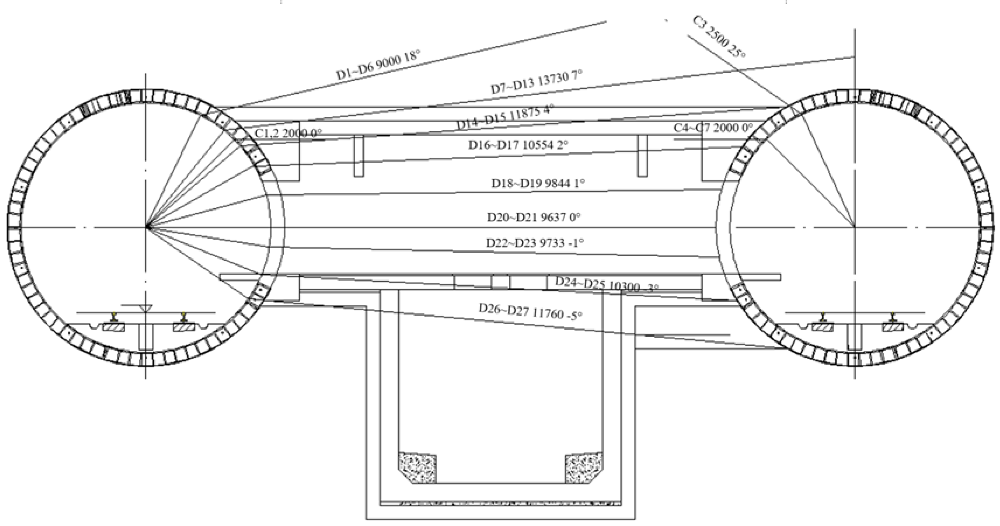
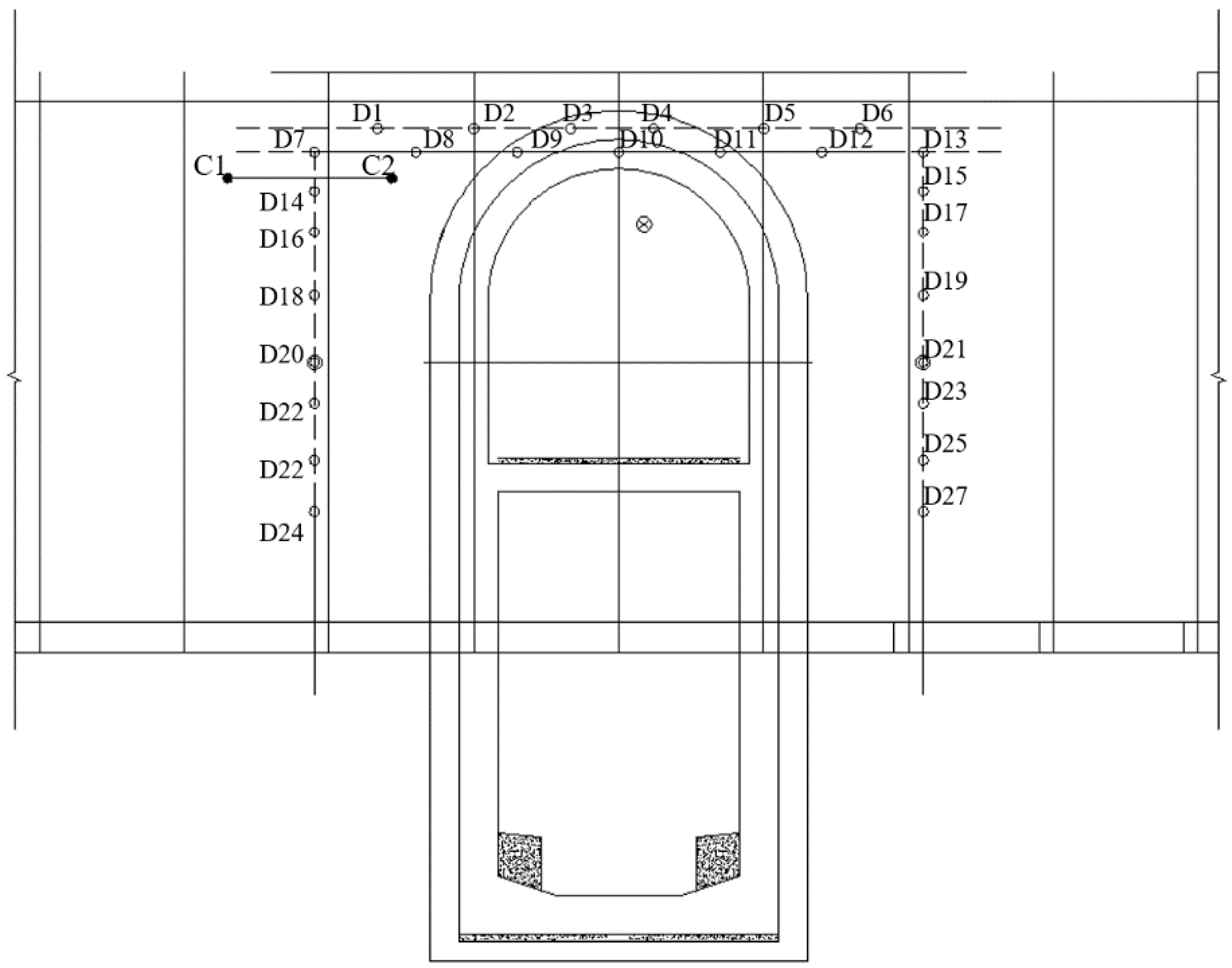
From the perspective of construction safety, the reinforcement scheme was revised as follows: part of the connecting passage was reinforced by the freezing method and was constructed by the mining method; part of the collecting well was still grouted with small duct grouting, and was constructed by the mining method; the structural design, therefore, remained unchanged.

2.2. Design Scheme

A schematic diagram showing the layout of the freezing holes is given in Figure 1, Figure 2 and Figure 3. The left-line tunnel was addressed, and the freezing holes were arranged on one side. As indicated in Figure 2, there were 27 freezing holes in total, which were arranged at three angles: horizontal, pitched up, and pitched down. The total length of the freezing holes was 300 m. Two penetration holes were provided in the middle of the channel for the freezing pipe arrangement of the opposite channel in any emergency. Seven temperature measuring holes, C1–C7, were set and their main purpose was to measure the temperature development condition of the freezing curtain range, so as to adopt comprehensive corresponding control measures to ensure construction safety. A pressure relief hole, X1, was arranged in the closed area of the freezing curtain.
The main parameters of the freezing construction are shown in Table 2. It is necessary to combine the temperature monitored by the temperature monitoring hole, the hole detection condition, the pressure relief hole pressure, and other factors to determine the timing of opening the pipe. It is necessary to meet the design requirement conditions shown in Table 3 before the excavation.

3. Methodology

3.1. Basic Assumptions

The basic assumptions of the numerical analysis were as follows: (1) the soil layer had a uniform initial temperature field, taken as 18 °C; (2) the temperature load was applied directly to the wall of the freezing pipe [20], ignoring the temperature difference of the brine circulation along the longitudinal direction of the freezing pipe; (3) the influence of water migration was ignored; (4) the soil layer parameters take as silty mudstone, which was regarded as homogeneous and thermal isotropic; (5) the freezing temperature of the soil layer was taken as −1 °C.

3.2. Calculation Model and Parameter Selection

According to the freezing hole arrangement scheme, the intersection point of the upper row tunnel axis and the longitudinal section axis of the connecting passage was set as the coordinate origin, with a dimension of the X-axis direction (longitudinal length) × Y-axis direction (lateral width) × Z-axis direction (vertical height) = 15.33 × 10 × 10 m. The 4-node meshing format was selected. The mesh near the freezing pipe area (frozen soil curtain) was dense, and the mesh was sparse away from the area, with a total of 1,464,495 elements. Figure 4 schematically shows the geometry and meshed model, using a transient thermal model with phase transition. Adiabatic boundary conditions were set on the outer boundary of the domain were set on the outer boundaries of the domain.
Table 4 shows the material parameters of the model obtained by the frozen soil tests [27,28,29]. In geometric modeling, the freezing pipe body is subtracted from the overall model by Boolean operation, leaving the surface of the freezing pipe as the thermal load boundary and the brine temperature as the boundary load. From the field-measured data, the process of brine cooling during the active freezing period is shown in Table 5. According to the cooling plan, the freezing time step was 40 d, and the length of each step was 24 h.
As shown in Figure 3, the drilling characteristics of the temperature measurement holes, C1–C7, are listed in Table 6. According to the layout of the temperature measuring holes, 7 paths and the analysis points on the corresponding positions of the numerical model were taken for the present study in order to analyze the temperature field distribution of the frozen soil curtain of the connecting passage. The analysis points on the 7 paths were set every 0.25 m.

3.3. Comparison between Numerical Model and Field-Measured Data

The three-dimensional finite element calculation results were compared with site measurements of the temperature field data to verify the correctness of the three-dimensional numerical model, and the temperature and time curves are plotted in Figure 5. As can be seen, the numerical calculation results were in close agreement with the measured temperature values from the site, and the freezing behavior was very similar. The numerical model simulated the actual situation well, indicating that the numerical simulation calculation method, numerical model, and related parameters were fundamentally correct. Therefore, it was feasible to use the three-dimensional numerical model to simulate the changed behavior of the frozen soil curtain temperature field of the connecting passage.

4. Results and Discussion

4.1. The Overall Situation of the Frozen Soil Curtain

Figure 6 shows the overall temperature of the frozen soil curtain after 40 days of freezing, including the temperature field cloud maps of the four sections x = −3.0, −6.0, −9.0, and −12.0 m, and the isotherms for −1 and −10 °C. It can be observed that after 40 days of active freezing, the thickness of the frozen soil curtain was greater than 2.0 m and the average temperature was lower than −10 °C, which has more surplus. The design freezing scheme, therefore, forms a continuous and stable frozen soil curtain, and the average temperature of the frozen soil curtain is relatively low, and thus the scheme was feasible. However, it can be deduced from the temperature field cloud map that the weakest part of the whole frozen soil curtain is the top of the bell mouth, where the right-line tunnel intersects with the connecting passage, which is the area with the greatest risk during the excavation of the entire connecting passage. Many engineering accidents relating to connecting passages have been caused by seepage due to inadequate freezing in that area. The top freezing hole in the area is formed by making a row of long holes from the side of the left-row freezing station to the right-row side. It is recommended to set a row of shorter freezing holes at the top of the right-row bell mouth in order to enhance the freezing effect of this area and ensure the safety of the construction of the connecting passage.

4.2. Frozen Soil Curtain Closure Conditions

Figure 7 is an isotherm diagram of −1 and −10 °C for different profiles at different times (x = −3.0, −6.0, −9.0, −12.0 m profiles from left to right). It is evident that the frozen walls start to form and slowly intersect with the freezing pipe at the center, and finally form a closed frozen soil curtain to achieve the water-stopping support effect. When frozen for 10 days, the closed soil frozen curtain has been formed on the x = −3.0 m section. When frozen for 12 days, the frozen soil curtains with x = −6.0 and x = −9.0 m profiles also are closed. When frozen for 14 days, the x = −12.0 m section also eventually forms a closed frozen soil curtain. At this time, the closed frozen curtain of the entire connecting passage has been formed, which therefore has reliable sealing performance. Thus, under this scheme, the frozen wall closure time, i.e., the time required to form a continuous and closed frozen soil curtain for a connecting passage, was 14 days. However, at this time, the strength and thickness of the entire frozen soil curtain have not yet met the design requirements. As the freezing time increases, the average temperature (strength) and thickness of the frozen soil curtain gradually increase, and when it has been actively frozen for 40 days, a completely stable frozen curtain with stable performance finally is formed. The frozen soil curtain closure conditions observed in this project may be applicable for other comparable project in evaluating the active freezing time.

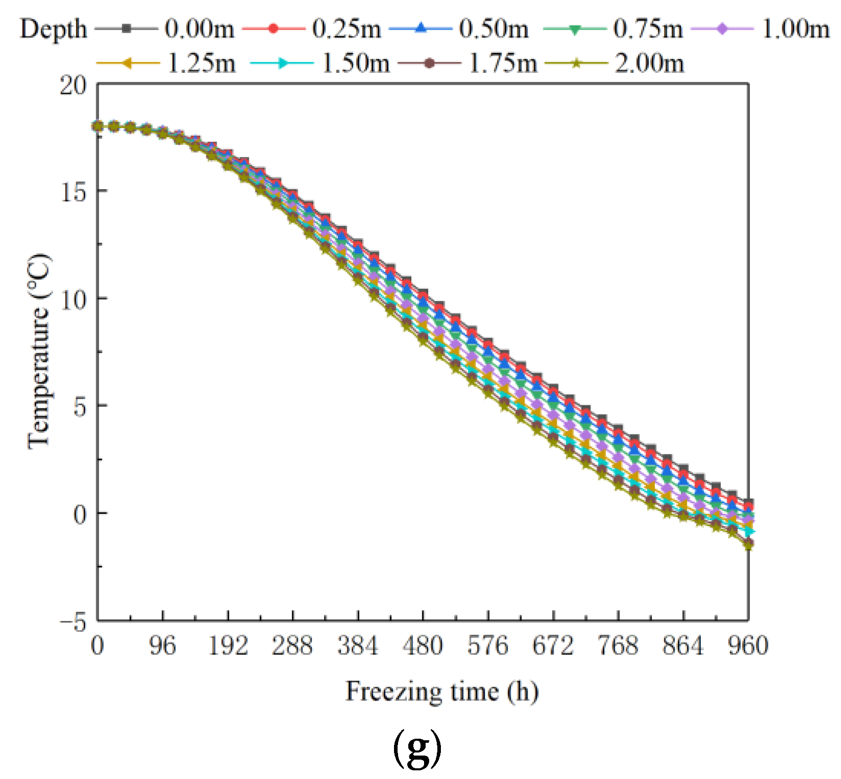
4.3. Freezing Process

In order to study the cooling behavior of the frozen soil curtain in the connecting passage and provide the judgment basis for the excavation construction, the C1–C7 temperature measurement holes were set and a temperature measuring point was set every 0.25 m. In this study, seven paths, as well as the analysis points on them, were taken in the positions corresponding to the numerical model. This was done in order to analyze the temperature field distribution of the frozen soil curtain of the connecting passage. Variations in the analysis point temperatures over time on the C1–C7 paths are shown in Figure 8.
It can be seen from the figure that: (1) the closer to the analysis point was the freezing pipe, the faster the temperature was lowered. (2) In C1, C4, and C7, there were analysis points with temperatures that were above 0 °C, but they only existed in locations where the temperature measurement hole was not deep. The deeper the analysis point, the lower the point temperature was, and finally it reached below 0 °C. (3) The thickness of the frozen soil curtain at three places, C1 and C2, C4 and C5, and C6 and C7, was above 1.75 m. The frozen soil curtain was relatively weak in these three places. If the thickness of the frozen soil curtain in these three places reaches 1.75 m or more, the whole frozen soil curtain will meet the design requirements, and the conditions are achieved for excavation construction. (4) The C3 path was selected to judge the extent of the freezing effect at the top of the right-line tunnel bell mouth. It can be observed that the middle part of the C3 path was the closest to the freezing pipe at a depth of 1.75 m and the temperature also fell rapidly. From the middle to the two sides, the temperature reduction was progressively slower and slower but finally fell below 0 °C. The results shown in Figure 6 indicate that the large space between freeze pipes require more freezing time to achieve a closed frozen curtain, which should be taken into account in design about the largest space between freeze pipes.

4.4. Engineering Application

The final reinforcement scheme for the connecting passage and pumping station project of Binhu Road Station / Jinhu Square Station of Nanning Metro Line 3 was made that the connecting passage can be partially reinforced by the freezing method and the mining method was used for construction. The collecting well section was still grouted with small ducts for reinforcement and was constructed by the mining method; the structural design remained unchanged. The freezing project began to freeze the holes on 12 May 2018. On 21 May, all the freezing holes were set up. A total of 27 freezing holes, 7 temperature measurement holes and 1 pressure relief hole, were set up. The freezing station was started on 25 May 2018, and was operated until 3 July 2018 (40 days of freezing), the average thickness of the frozen soil curtain was 2.4 m, the average temperature was −10.7 °C, and the freezing effect met the design requirements. The data reported by real-time monitoring of the temperature field of the freezing project showed that the actual project finally formed a well-frozen soil curtain. When the pipe was opened for excavation, there was no water leakage or sand leakage. Thus, under the protection of the curtain in the frozen soil, smooth excavation of the connecting passage was ensured, and it was proved that the above-mentioned connecting passage freezing scheme was effective.
From the analysis of the freezing period can be observed that, during the freezing process, the thermal conductivity and water content are key parameters in affecting the temperature decline. In reality, these two parameters usually have some spatial variability [30], which will hinder the target temperature to be achieved. In order to mitigate the effect of those parameters’ spatial variability, an appropriate longer freezing period should be considered so as to achieve the design requirements.

5. Conclusions

This study reported the engineering background of using the ground freezing method to reinforce the No. 2 connecting passage of Binhu Road Station/Jinhu Square Station of Nanning Metro Line 3. A finite element software was used to establish a three-dimensional numerical model of the connecting passage and its surrounding soil layers. The development behavior of the soil curtain temperature field was monitored and the evolution of the frozen soil curtain was dynamically simulated. The following conclusions can be drawn based on the analysis.
(1)
Measured values from the construction site and numerical modeling calculation results exhibited good agreement and the progression of the freezing process was similar in both instances. The work demonstrated that it is feasible to simulate the changing process of the frozen soil curtain temperature field of a connecting passage using a three-dimensional numerical model;
(2)
The weakest link in the frozen soil curtain is the top of the bell mouth where the downhole tunnel intersects the connecting passage. This feature was consistent with the findings of Ref. [3]. On the basis of the information obtained during the present study, it is recommended that a row of shorter freezing holes should be made at the top of the downline bell to enhance the freezing effect in this area and ensure safety during the construction of the connecting passages;
(3)
Under the design freezing scheme, the frozen wall closure time was 14 days. As the freezing time increased, the thickness and average temperature (strength) of the frozen soil curtain gradually increased, eventually forming a completely closed and stable frozen soil curtain;
(4)
The thickness of the frozen soil curtains of C1 and C2, C4 and C5, and C6 and C7 reached 1.75 m or more, indicating that the entire frozen soil curtain met the design requirements and the conditions necessary for safe excavation and construction were achieved;
(5)
The freezing project started on 25 May 2018, and lasted until 3 July 2018 (40 days of freezing). The average thickness of the frozen soil curtain was 2.4 m, the average temperature was −10.7 °C, and the freezing effect met the design requirements. The successful excavation of the site project suggested that it was feasible to adopt the above-mentioned connecting passage freezing scheme, which may provide references for comparable projects using artificially freezing ground in metro station construction.
As a limitation, in the current study, only the temperature field has been considered for waterproofing purposes. The soil’s mechanical behavior (e.g. frost heave and moisture migration) under temperature change and heat transfer, as well as the possibilities of the numerical calculation program to optimize the number of freezing holes, their location and length will be examined as future work.

Author Contributions

Conceptualization, B.W.; methodology, X.L.; software, X.L.; validation, J.H., X.L. and H.Z.; formal analysis, X.L.; investigation, X.L.; resources, H.Z.; data curation, X.L.; writing—original draft preparation, B.W.; writing—review and editing, B.W.; visualization, X.L.; supervision, J.H.; project administration, H.Z.; funding acquisition, H.Z. All authors have read and agreed to the published version of the manuscript.

Funding

This research was funded by the Innovative Research Team Project of Natural Science Foundation of Hainan Province, P. R. China (522CXTD511), High Technology Direction Project of the Key Research & Development Science and Technology of Hainan Province, P. R. China (Grant No. ZDYF2021GXJS020), characteristic innovation (Natural Science) projects of scientific research platforms and scientific research projects of Guangdong Universities in 2021 (Grant No. 2021KTSCX139), and Jiangmen Basic and Applied Basic Research Key Foundation (Grant No. JZ202214).

Institutional Review Board Statement

Not applicable.

Informed Consent Statement

Not applicable.

Data Availability Statement

The data used to support the findings of this study are available from the corresponding author upon request.

Conflicts of Interest

The authors declare that they have no conflict of interest.

References

  1. Evirgen, B.; Tuncan, M. A physical soil freezing model for laboratory applications. Cold Reg. Sci. Technol. 2019, 159, 29–39. [Google Scholar] [CrossRef]
  2. Zhou, M.M.; Meschke, G. A three-phase thermo-hydro-mechanical finite element model for freezing soils. Int. J. Numer. Anal. Methods Geomech. 2013, 37, 3173–3193. [Google Scholar] [CrossRef]
  3. Hu, J.; Wei, H.; Liu, Y. Temperature field development at cross-passage of subway improved by ground freezing method. Mod. Tunn. Technol. 2015, 53, 285–292. (In Chinese) [Google Scholar]
  4. Hussin, J.D. Methods of soft ground improvement. In The Foundation Engineering Handbook; CRC Press: Boca Raton, FL, USA, 2006; pp. 529–565. [Google Scholar]
  5. Liu, Y.; Lee, F.H.; Quek, S.T.; Chen, E.J.; Yi, J.T. Effect of spatial variation of strength and modulus on the lateral compression response of cement-admixed clay slab. Géotechnique 2015, 65, 851–865. [Google Scholar] [CrossRef]
  6. Liu, Y.; Jiang, Y.J.; Xiao, H.W.; Lee, F.H. Determination of representative strength of deep cement-mixed clay from core strength data. Géotechnique 2017, 67, 350–364. [Google Scholar] [CrossRef]
  7. Russo, G.; Corbo, A.; Cavuoto, F.; Autuori, S. Artificial ground freezing to excavate a tunnel in sandy soil. Measurements and back analysis. Tunn. Undergr. Space Technol. 2015, 50, 26–238. [Google Scholar] [CrossRef]
  8. Zhang, Z.Q.; He, C. Study on construction of cross connection of shield tunnel and connecting aisle by freezing method. Chin. J. Rock Mech. Eng. 2007, 24, 3211–3217. (In Chinese) [Google Scholar]
  9. Li, D.Y.; Cao, L.X.; Li, J. Analysison influence of seepage in a cross passage on frozen walls by numerical simulation method. Chin. J. Undergr. Space Eng. 2012, 8, 111–115. [Google Scholar]
  10. Qin, W.; Yang, P.; Jin, M.; Zhang, T.; Wang, H.B. Application and Survey Analysis of Freezing Method Applied to Ultra-long Connected Aisle in Metro Tunnel. Chin. J. Undergr. Space Eng. 2010, 6, 1065–1071. (In Chinese) [Google Scholar]
  11. Li, S.; Lai, Y.; Zhang, M.; Zhang, S. Minimum ground pre-freezing time before excavation of Guangzhou subway tunnel. Cold Reg. Sci. Technol. 2016, 46, 181–191. [Google Scholar] [CrossRef]
  12. Marwan, A.; Zhou, M.M.; Abdelrehim, M.Z.; Meschke, G. Optimization of artificial ground freezing in tunneling in the presence of seepage flow. Comput. Geotech. 2016, 75, 112–125. [Google Scholar] [CrossRef]
  13. Vitel, M.; Rouabhi, A.; Tijani, M.; Guérin, F. Modeling heat transfer between a freeze pipe and the surrounding ground during artificial ground freezing activities. Comput. Geotech. 2015, 63, 99–111. [Google Scholar] [CrossRef]
  14. Li, P.; Xie, X.Y.; Ji, Q.Q. Dynamic evolution analysis on frozen wall temperature of cross passage of Shanghai Yangtze river tunnel. J. Tongji Univ. (Nat. Sci.) 2013, 41, 515–521. (In Chinese) [Google Scholar]
  15. Li, P.; Xie, X.Y. Research on Optimization of Freezing-temperature Monitoring Design and Method of Data Analysis in Shanghai Yangtze River Tunnel. Chin. J. Undergr. Space Eng. 2012, 8, 122–128. [Google Scholar]
  16. Li, P.; Li, D.; Tang, X.; Liu, Y. Hydrothermal performance of in-tunnel ground freezing subjected to drilling inaccuracy and seepage flow. ASCE-ASME J. Risk Uncertain. Eng. Syst. Part A Civ. Eng. 2022, 8, 01195. [Google Scholar] [CrossRef]
  17. James, J.; Karthickeyan, S.; Chidambaram, S.; Dayanadan, B.; Karthick, K. Effect of curing conditions and freeze-thaw cycles on the strength of an expansive soil stabilized with a combination of lime, jaggery, and gallnut powder. Adv. Civ. Eng. 2018, 2018, 1813563. [Google Scholar] [CrossRef] [Green Version]
  18. Hu, J.; Liu, Y.; Wei, H.; Yao, K.; Wang, W. Finite-element analysis of the heat transfer of the horizontal ground freezing method in shield-driven tunneling. Int. J. Geomech. 2017, 17, 04017080. [Google Scholar] [CrossRef]
  19. Qiu, P.; Li, P.; Hu, J.; Liu, Y. Modeling seepage flow and spatial variability of soil thermal conductivity during artificial ground freezing for tunnel excavation. Appl. Sci. 2022, 11, 6275. [Google Scholar] [CrossRef]
  20. Alzoubi, M.; Madiseh, S.A.G.; Hassani, F.P.; Sasmito, A.P. Heat transfer analysis in artificial ground freezing under high seepage: Validation and heatlines visualization. Int. J. Therm. Sci. 2019, 139, 232–245. [Google Scholar] [CrossRef]
  21. Vitel, M.; Rouabhi, A.; Tijani, M.; Guérin, F. Modeling heat and mass transfer during ground freezing subjected to high seepage velocities. Comput. Geotech. 2016, 73, 1–15. [Google Scholar] [CrossRef]
  22. Liu, Y.; Hu, J.; Xiao, H.W.; Chen, E.J. Effects of material and drilling uncertainties on artificial ground freezing of cement-admixed soils. Can. Geotech. J. 2017, 54, 1659–1671. [Google Scholar] [CrossRef]
  23. Liu, Y.; He, L.Q.; Jiang, Y.J.; Sun, M.M.; Chen, E.J.; Lee, F.H. Effect of in situ water content variation on the spatial variation of strength of deep cement-mixed clay. Géotechnique 2019, 69, 391–405. [Google Scholar] [CrossRef] [Green Version]
  24. Li, K.Q.; Li, D.Q.; Liu, Y. Meso-scale investigations on the effective thermal conductivity of multi-phase materials using the finite element method. Int. J. Heat Mass Transf. 2020, 151, 119383. [Google Scholar] [CrossRef]
  25. Li, K.Q.; Miao, Z.; Li, D.Q.; Liu, Y. Effect of mesoscale internal structure on effective thermal conductivity of anisotropic geomaterials. Acta Geotech. 2022, 17, 3553–3566. [Google Scholar] [CrossRef]
  26. Li, K.Q.; Liu, Y.; Yin, Z.Y. An improved 3D microstructure reconstruction approach for porous media. Acta Mater. 2023, 242, 118472. [Google Scholar] [CrossRef]
  27. Hu, J. Study on the Reinforcement Methods of Subway Large-Diameter Shield Launching in the Sandy Clay with High Water Pressure. Ph.D. Thesis, Nanjing Forestry University, Nanjing, China, 2012. [Google Scholar]
  28. Hu, J.; Yang, P. Numerical analysis of temperature field within large-diameter cup-shaped frozen soil wall. Rock Soil Mech. 2015, 36, 523–531. [Google Scholar]
  29. Kim, Y.; Hwang, B.; Cho, W. Development of ground freezing system for undisturbed sampling of granular soils. Adv. Civ. Eng. 2018, 2018, 1541747. [Google Scholar] [CrossRef]
  30. Liu, Y.; Li, K.Q.; Li, D.Q.; Tang, X.S.; Gu, S.X. Coupled thermal–hydraulic modeling of artificial ground freezing with uncertain-ties in pipe inclination and thermal conductivity. Acta Geotech. 2022, 17, 257–274. [Google Scholar] [CrossRef]
Figure 1. Elevation profile of the connecting passage (diameter of tunnel: 6.3 m; center to center distance: 15.3 m).
Applsci 13 00671 g001
Figure 2. Layout of freezing holes on the machine room side.
Applsci 13 00671 g002
Figure 3. Contralateral freezing hole layout.
Applsci 13 00671 g003
Figure 4. Mesh size and geometric size of the numerical model. (a) mesh and geometric size of the model; (b) distribution of freeze pipes.
Applsci 13 00671 g004
Figure 5. Comparison between simulated results and site data. (a) Measuring point 1, (b) measuring point 2.
Applsci 13 00671 g005
Figure 6. Freezing curtain under 40-day freezing. (a) x = −3.0 m, (b) x = −6.0 m, (c) x = −9.0 m, (d) x = −12.0 m.
Applsci 13 00671 g006
Figure 7. Isotherms for −1 and −10 °C for various freezing times. (a) Actively frozen for 6 days, (b) actively frozen for 8 days, (c) actively frozen for 10 days, (d) actively frozen for 12 days, (e) actively frozen for 14 days.
Applsci 13 00671 g007aApplsci 13 00671 g007b
Figure 8. Temperature changes at points C1–C7 against freezing time. (a) C1 path, (b) C2 path, (c) C3 path, (d) C4 path, (e) C5 path, (f) C6 path, (g) C7 path.
Applsci 13 00671 g008aApplsci 13 00671 g008b
Table 1. Comparison of common construction methods for connecting passages of metro station.
Construction MethodsScope of ApplicationsEnvironmental Impact
Open-cut methodApplicable to all kinds of soil layers, the construction technology requirements are low, and the failure of the connecting passage construction has less impact on the main tunnel structure.Great impact on the environment and occupying a large site
Undercut methodDeep mixingUsing soft clay with impact, when the quality of the soil reinforcement is not good enough, it will easily cause the collapse of the face and the leakage of the roof during the excavation process.Need to block traffic and have noise pollution
Freezing methodApplicable to all kinds of soil layers, especially suitable for soil layers with high water content or with confined water. The soil has high reinforcement strength, good water-stopping performance and does not occupy the site area.No pollution on the ground and no noise
Pipe-jacking methodSuitable for soil layers with small water content and good self-supporting properties. Jacks have an impact on the stability of the main tunnel.Poor top force control will cause displacement of the main tunnel
Mineshaft methodConstruction quality cannot be guaranteed, causing collapse or gushing.Need to block traffic, with mud, noise pollution, and land subsidence
Table 2. Operational parameters during ground freezing.
ParameterUnitValueRemarks
Frozen soil curtain design thicknessm2/
Frozen soil curtain average temperature°C≤−10The average temperature of the interface between frozen soil curtain and pipeline sheet ≤−5 °C
Frozen soil curtain closure timeDay22–25/
Active freezing timeDay35/
Number of freezing holes 27/
Freezing hole control spacingm1.5/
Freezing hole allowable verticality deviationmm300When the deflection exceeds the standard, it is decided whether to fill the hole according to the comprehensive situation of the deflection.
Designed minimum brine temperature°C−25~−28The saltwater temperature gets below −20 °C after freezing for 7 days
Maintain freezing brine temperature°C≤−25/
Single-hole brine flowm3/h3~5/
Freezing pipe specificationmmΦ89 × 8Low carbon steel seamless steel pipe
Number of temperature-measuring holes 7Φ89 × 8 or Φ32 × 2.5
Number of pressure relief holes 1/
Total length of freezing pipemm297.516/
Total cooling capacity of freezing104 kcal/h3.5According to specific working conditions
Table 3. Technical indices in the excavation of cross-passage.
ProjectsValueRemarks
Installation of tunnel support and protective doors/Emergency materials are fully equipped
Remote monitoring facilities for connecting passages and tunnels are all ready//
Frozen curtain average temperature−10 °CCalculated by the icing prediction formula
Brine temperatureActive period−25 °C or lessMonitoring with a thermometer
Maintenance period<−25 °C
The temperature difference of brine outlet and inlet loopActive periodWithin 2 °CDecrease the temperature to design value
Maintenance periodWithin 1.0 °C/
Pressure relief holeBefore closureHydrostatic pressureObserved by a pressure gauge, and no water, mud flowing out.
Table 4. Thermal parameters of soils.
Soil LayerDensity/(kg·m−3)Water Content/%Thermal Conductivity/(kJ·m−1·d−1·°C−1)Specific Heat/(kJ·kg−1·°C−1)Phase Change Latent Heat/(×108 J/m3)Freeze Temperature Range/(°C)
Unfrozen SoilFrozen SoilUnfrozen SoilFrozen Soil
Silty mudstone118016.81181791.531.611.20[−1, 0]
Table 5. Freezing time plan for brine temperature.
Time/d0151015203040
Temperature/°C18−2.5−30−30−30−30−30−30
Table 6. List of temperature measuring hole drilling characteristics.
Hole TypeHole NumberNumber of HolesHole Depth (m)Positioning Angle (°)Punch Elevation Angle (°)Punch Horizontal Angle (°)Total Hole Depth (m)
Temperature measuring holeC1–C222.045004.0
C4–C742.045008.0
C313.0653503.0
Disclaimer/Publisher’s Note: The statements, opinions and data contained in all publications are solely those of the individual author(s) and contributor(s) and not of MDPI and/or the editor(s). MDPI and/or the editor(s) disclaim responsibility for any injury to people or property resulting from any ideas, methods, instructions or products referred to in the content.

