Article

A Methodical Approach to 3D Scanning of Heritage Objects Being under Continuous Display

1
Department of Computer Science, Faculty of Electrical Engineering and Computer Science, Lublin University of Technology, Nadbystrzycka 36B, 20-618 Lublin, Poland
2
Department of Design Engineering and Robotics, Technical University of Cluj-Napoca, 400114 Cluj-Napoca, Romania
3
Department of Information Systems Engineering, Faculty of Management, Lublin University of Technology, Nadbystrzycka 38, 20-618 Lublin, Poland
*
Author to whom correspondence should be addressed.
Appl. Sci. 2023, 13(1), 441; https://doi.org/10.3390/app13010441
Submission received: 3 December 2022 / Revised: 18 December 2022 / Accepted: 26 December 2022 / Published: 29 December 2022

Abstract

:
Three dimensional digitization of cultural heritage resources gains a lot of attention from the European Union and the United Nations, which is clearly revealed in current strategic goals and financing perspectives. Existing methodological approaches to 3D scanning in a prevailing number of cases assume that the procedure of scanning is performed in places that are closed to tourists, at least for the time of scanning. However, closing an exhibition for tourists or moving an artifact to be scanned is not always possible. Thanks to the long-term experience of the authors with 3D scanning of cultural heritage, the special procedure was designed for small and medium size objects to overcome difficulties expected in such cases. The procedure has been successfully implemented during 3D scanning of objects exhibited in the Silk Road region (on the territory of modern Uzbekistan), as well as objects being parts of wooden sacral architecture of the Maramures region (in Romania). It was revealed that the proposed procedure was successfully allowed to counteract organizational problems during 3D scanning of heritage objects being under continuous display, and that the achieved results of scanning were nevertheless of good quality.

1. Introduction

1.1. Digitization of Cultural Heritage

Three dimensional digitization of cultural heritage resources is gaining a lot of attention from international and governmental institutions, which is clearly revealed in their current strategic goals and financing perspectives. The European Union is one of the entities very active in this field, to mention the initiative called “New European BauHaus” aimed at building a sustainable and inclusive future among others by addressing complex societal problems and creating a bridge between science, technology and culture [1]. Maintaining heritage within the shared European cultural space and adapting it for the future is a key concept [2]. Funding for heritage preservation is granted under the Horizon Europe as well, for example the “Culture, creativity and inclusive society” programme [3]. Another example is the United Nations and its Development Programme (Standard 4: Cultural Heritage). Cultural heritage preservation, protection and promotion in a manner consistent with the UNESCO cultural heritage conventions is mentioned as the aim [4].

1.2. The Problem of 3D Digitization of Historical Objects in Museums

Existing methodological approaches to 3D scanning in a prevailing number of cases assume that the procedure of scanning is performed in places that are closed to tourists, at least for the time of scanning. Such an approach gives the best results, thanks to the time available and the possibility of free positioning of a scanner. Such conclusions might be derived from the authors’ own works [5,6,7,8,9,10,11] as well as from others [12,13,14,15].
However, closing an exhibition for tourists, or moving an artifact to be scanned, is not always possible. Such an action might be unacceptable for a museum. Additionally moving an artifact might not be possible, e.g., because it is part of an architectural object, a collection to which the artifact belongs is in permanent exhibition, moving the artifact is too difficult or risky, a procedure of loaning it creates too much trouble and risk, etc. In such cases, the only thing left to consider is scanning at the point of exposure of the objects (Figure 1).

1.3. Study Motivation

The authors have experienced the above-mentioned problems during their work and successfully found appropriate solutions. As a result, they have developed a methodical approach (called “3DScaMITE”—3D Scanning Methodology in Intensive Tourism Environment) for scanning large architectural objects under continuous tourist traffic and applied it successfully in scanning the Timurid architecture in Central Asia [16]. Nevertheless, the gap concerning a methodical approach to 3D scanning of small and medium sized objects under continuous display is still present.
Thus, the authors decided to present in this work the methodical approach to 3D scanning of small- and medium-sized heritage objects in the cases when closing an exhibition for tourists, or moving an object to be scanned, is not possible. The methodology was created in order to overcome difficulties expected in such cases, as a result of long-term experience of the authors with 3D scanning of cultural heritage objects. It was developed and verified on the basis of experimental implementation of 3D scanning sessions in state museums of Uzbekistan (Afrasiab in Samarkand and in Tashkent) as well as during the scanning of wooden sacral architecture in the Maramures region in Romania. Additional value of this work, aside from introducing a new methodology, is complying with the goals and needs of European Union and United Nations initiatives.

2. Study Background

In situ digitization of heritage objects is usually affected by the following difficulties: the necessity to bring and set-up the equipment needed during digitization; limited access to heritage objects and safety of their extraction; as well as ongoing tourist traffic.
Digitization of tangible cultural heritage objects can be implemented in many ways, in terms of technology as well as conditions for data acquisition and access to heritage site facilities. Daneshmand et al. in [17] present a variety of technological solutions suitable for 3D digitization. Most of the solutions are based on aerial and terrestrial photogrammetry, although the role of terrestrial laser scanning usage in data acquisition is mentioned as well. The authors also give examples of 3D reconstruction of architectural structures, i.e., the remains of Las Higueras city (Argentina) and historical buildings such as the Rohan Palace facade, the Catholic church of St-Pierre-le-Jeune, the Josephine Pavilion in Strasbourg (France), the Byzantine Land Walls of Istanbul (Turkey) or the Temple of the Sacred Tooth Relic at Kandy (Sri Lanka). Architectural details were acquired by means of a hand-held scanner using Artec’s structured light technology. However, the authors did not pay attention to the aspects related to local (in situ) conditions concerning (influencing) the digitization process, despite the fact that these objects were frequently visited by tourists.
Miłosz et al. in [18] present various theoretical aspects regarding the issues of 3D digitization of architectural and museum objects, as well as many practical implementations. Some of the described devices have significant limitations in their use in situ, e.g., stationary chamber scanners (Roland PICZA 3D Laser Scanner LPX-600) have a small working space and cause difficulties in transport due to their large weight and size. Another presented device—ZScanner ® 700, which is a hand-held laser scanner, requires placing markers on the surface of a digitized object, which is usually not allowed in the case of historic objects [19]. A confirmed drawback of these devices is the inability to collect information about the texture of scanned objects, which limits their use in transferring cultural heritage to the digital world. Kowalski et al. in [20] present a low-cost 3D data acquisition system for small objects using a set of Kinect v2 devices cooperating with the open source LiveScan3D software. Unfortunately, there are a lot of cases requiring more professional solutions in terms of precision, range, durability, ability to deal with environmental factors.
Tucci et al. in [21], apart from the above-mentioned aspects, deal with the topic of 3D reconstruction. Practical implementation of activities concerning the 3D digitization of heritage objects can be found in many other works, to mention creating virtual spaces [22,23] or the scanning of: the Hercules statue from the Antalya Museum in Turkey and the Khmer head from the Rietberg Museum in Zurich [24]; a complex of historic buildings in Malacca, Malaysia, declared a UNESCO World Heritage Site in 2008 [25]; artifacts in the area of Sarmisegetuza Regia archaeological site [26]. Nevertheless, in the opinion of the authors of this article, the topic of 3D scanning of heritage objects being under continuous display was not addressed as it needs to be. What is more, there is a wide agreement that there are not enough free databases that could be used for comparative tests of algorithms and procedures [17,27,28,29].
Few works address issues related to accessing heritage objects and dealing with particular conditions of heritage sites subjected to 3D scanning. Montusiewicz et al. in [5] present many problems related to removing objects to be scanned from an exhibition and preparing them for 3D scanning process. In order to extract the objects from the showcases from the 1970s, several museum employees offered their cooperation. Some objects needed re-forming after being extracted. Construction of the scanning stage required a lot of ingenuity and depended on the nature of the object. On the other hand, there is the case of the County Museum in Nysa [30], where wooden polychrome sculptures from the 16th/17th centuries were digitized. The work was carried out in exhibition halls with diffused lighting, where the objects were put on special pedestals without additional covers, with omnidirectional access. Due to the prevailing COVID-19 pandemic, there were no visitors in the museum halls, which made it much easier to carry out all the works.
Another kind of problem, when 3D digitizing heritage objects is ongoing tourist traffic, resulting in visitors being scanned altogether with the object [16,31,32]. Girelli et al. in [31] the describe usage of photogrammetry to generate a detailed photo-textured 3D model of a fountain. The result, which was noisy due to the constant presence of people, was cleaned by applying a manual procedure. Miłosz et al. in [16] present the problems of digitizing large architectural objects in Registan (Samarkand, Uzbekistan), using Faro’s terrestrial laser scanner, with intensive tourist traffic. The method of removing visitors from scans is described by Kęsik et al. in [32].
Summing up, the information obtained from the analyzed articles, it appears that the issue of 3D scanning in in situ conditions is treated marginally. This may be the result of the fact that the 3D digitization of tangible cultural heritage is incidental, not systematic. Preparing operation procedures for teams undertaking these activities and describing the various emerging problems is an important issue when undertaking continuous digitization by many independent teams in various museums around the world. Another aspect which should be addressed in the future is the sustainability aspects concerning heritage sites and their surroundings [33,34,35,36,37].

3. Research Question

Persons working in the real environment on 3D digitization of heritage artifacts being under continuous display encounter a common set of problems. According to the authors’ experience these might be:
  • work in the conditions of ongoing tourist traffic,
  • logistical and legal problems related to the removal of exhibits from the exhibition hall,
  • the need to organize temporal scan locations,
  • inability to move some exhibits,
  • inability to remove some exhibits from the showcase.
Some of the abovementioned problems were addressed in the case of large architectural objects by the “3DScaMITE” methodology [16]. However, there is a still need to address these problems in the case of small- and medium-sized objects. In order to fill the identified gap, the authors in this work propose a new methodical approach (called “3DScaMOTO”) and pose the following research question:
Is it possible to acquire, in an effective way, 3D scans using 3D scanners, specifically based on structured light, of historical objects while not removing these objects from their original area of exhibition?
In order to answer the research question and verify the proposed method, the authors conducted a number of 3D scanning sessions of the Central Asia and Maramures regions heritage. From the huge variety of artifacts, the following were chosen as the case studies: the figure of two snakes from the State Museum of the History of Uzbekistan in Tashkent, the statue of Buddha from the Fayaztepa complex (Uzbekistan) and the icon of Saint Nicholas of Myra in Păușa (Romania).

4. Materials and Methods

4.1. Identification of Object Classes in Terms of Posed Scanning Difficulties

Based on the authors’ experience, the heritage sites may contain several types of objects in terms of the possibility of scanning them. To name them:
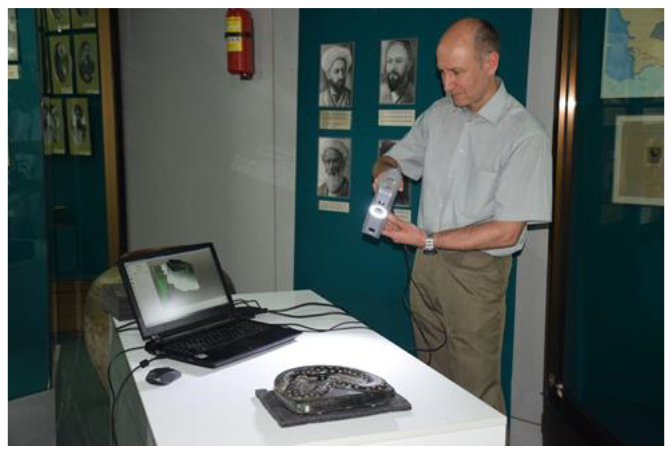
  • A. It can be moved from an exhibition place to an ad hoc scanning studio. Objects of small dimensions and weight, in condition (shape) that allows them to be moved within the exposure area in accordance with the procedures indicated by a heritage site.
  • B. It cannot be moved from an exhibition place. It has to be scanned at the place of exposure, but there is free access to it. The object cannot be moved, for example, because of: its size and weight, its permanent connection with the rest of the exhibition (e.g., base-relief), no permission to move the object due to its condition or even an alarm system.
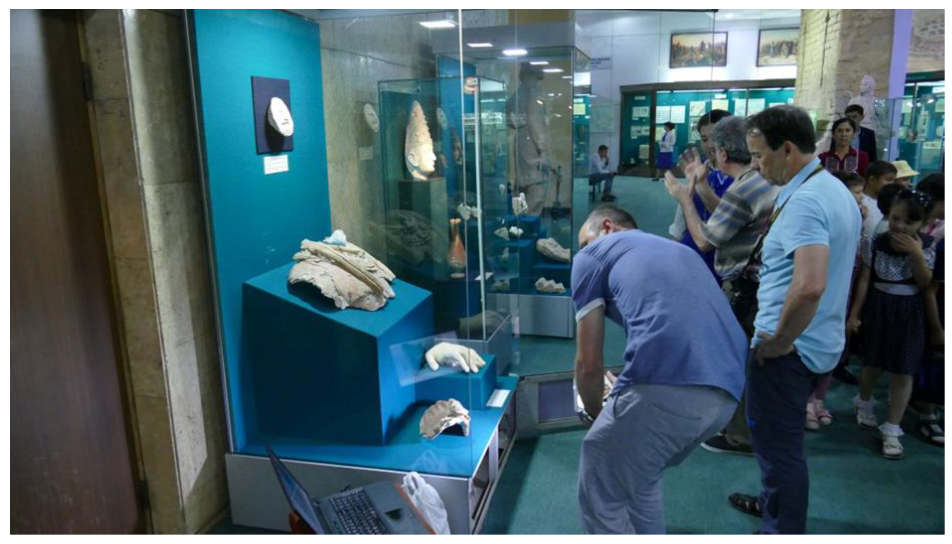
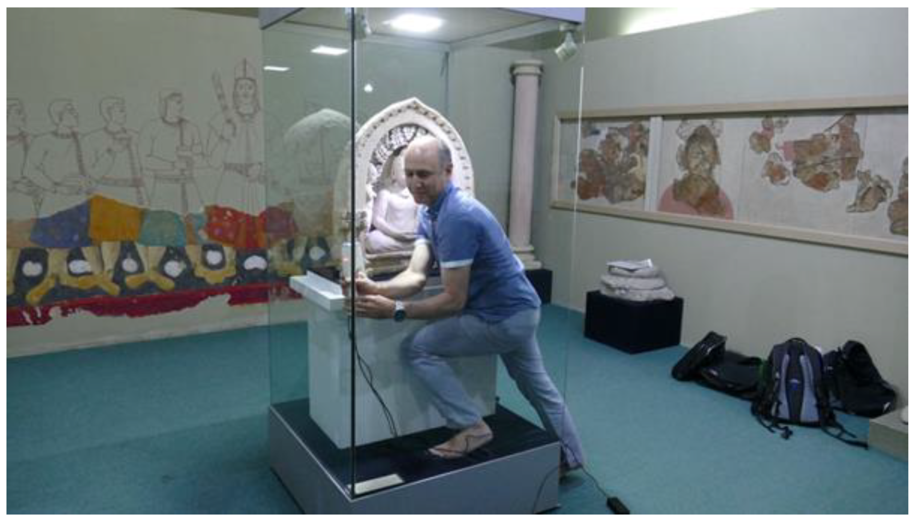
  • C. It cannot be moved from the exhibition place. It has to be scanned at the place of exposure and access to it is difficult. Such objects are B-type objects, although the access to them is additionally hampered by non-removable physical protections in the form of display cases, windows, bars, etc.
  • D. It cannot be scanned at all. No access and/or consent from the facility is granted.
The “3DScaMOTO” methodology, presented in detail in the next subsection, takes into account the presence of all the three types of objects (A, B, C) for which 3D scanning is potentially possible.

4.2. Description of the “3DScaMOTO” Methodology

This section introduces a methodical approach for 3D scanning of small- and medium-sized objects under continuous display. It was called “3DScaMOTO”, which means “3D Scanning Methodology in the Open for Tourists Objects”. See Table 1 for details on particular stages and their outcomes. Groups A, B, C from the table refer to object types characterized in Section 4.1. The methodology is not limited exclusively to museums but is valid for all heritage sites that are open for tourist traffic and for objects of dimensions that are within the capabilities of structured-light 3D scanners.
The initial stage (number 1—Planning) of the methodology covers the preliminary steps before actual 3D scanning. The cultural heritage site (which can be a museum, a historical place or any other site where heritage objects are placed) has to be examined and objects to be scanned have to be chosen. Once the list of objects is created the team of specialists, together with representatives of the site authorities, assign the objects to the A, B, C, and D groups.
In the case when some objects are assigned to the A group, the place for the future ad hoc scanning studio is chosen. The requirements for media (e.g. availability of electric current) are agreed according to each group of objects. At this stage the list of chosen objects is reconsidered taking into account the media limitations, constraints imposed by the site authorities and the feasibility assessment of the scanning. The result is the final, approved list of objects. The list is then rearranged according to the planned order of scanning and the naming convention is chosen so that thematic groups can be easily distinguished.
Onsite replanning takes place just before the scanning session. The agreed conditions are checked, and countermeasures are implemented if any problems arise. A verified scanning sequence plan is created, taking into account any changes in the sequence forced by the situation (e.g., the need to temporarily restore tourist traffic). After that, the 2nd stage can be initiated.
The 2nd stage is entirely about the proper 3D scanning execution. It is the last stage that has to be carried out at a heritage site—further stages might be executed in convenient time and place. If there are any type A objects on the list, the ad hoc studio is set-up to provide the best possible environment for scanning. The 3D scanning procedure is executed slightly differently, depending on the type of object being scanned. For type A objects, 3D scanning is carried out in the following sequence: transferring the object to the scanning station in the ad hoc studio (carried out by heritage site staff), selection of parameters, actual scanning, initial check of the results (if there are problems, scanning of the relevant fragments is repeated), collection of additional data about the scanned object (photographic and descriptive documentation), returning the object to the exhibition site (again carried out by heritage site staff).
In the case of type B objects, the 3D scanning procedure begins with preparation of the exhibition site (e.g. removing obstacles and setting additional lighting). The scope of the exhibition site modification depends on the decision of heritage site staff. Permission has to be obtained each time for each modification. Then, the object is 3D scanned, taking into account the constraints of a given place. The rest of the procedure is analogous as in the case of type A objects. Results should undergo preliminary checking—problematic places might be scanned again if necessary. When the scanning process is completed, the object’s exhibition site has to be restored to its normal condition.
In the case of type C objects, the procedure is analogous to the case of type B objects. The difference is taking into account difficulties in accessing an object to be scanned. Only during the scan, it is possible to determine how much the existing limitations interfere with the proper scanning process. Some counteracting methods could be introduced depending on the situation, e.g., scanning from a different position, making multiple scans of difficult area fragments, using a different scanning device and/or additional handles.
Stage 3 is about transforming gathered 3D scans into a high-resolution 3D mesh model of the scanned object (called 3D base model). During the scan preparation, the collected data for individual scanned objects are analyzed. Correctness of the object tagging (name and description) is confirmed, and potential errors in the description detected. 3D scans are analyzed in terms of their suitability for building a base 3D model. Rejecting inaccurate or low-quality scans saves time during actual processing. The result of this step are verified object scan data, ready for processing.
Another step is actual processing of scan data (full processing). The data are first cleared of unnecessary elements, then partial scans are aligned to each other. After successful alignment, a global point cloud of the entire object is generated.
During the final mesh processing, the point cloud is converted to a mesh of triangles. Obtained 3D model is cleared of unnecessary elements generated by the triangularization algorithm. It might also be analyzed against mesh discontinuities that could later undergo a fixing procedure. At last, color and texture are applied in order to make the 3D model look like the original object.
Stage 4 can be performed for 3D models produced in stage 3. It is not mandatory—it is executed as the need arises to present (disseminate) obtained results. First, the required technical parameters of the presentation are analyzed. In the next step, the base 3D model is converted to its dissemination version. The result has to be tested to see if it meets the requirements of presentation. If not, it has to be remade. Sometimes it has to be repeated multiple times. When the achieved effect is satisfactory, the model can be arranged in the presentation area and published. Very often dissemination models are of worse quality than base models, in order to comply with performance limitations of technologies used to create the presentation.

4.3. Case Studies Description

The 3DScaMOTO methodology can be used in 3D digitization independently of the way objects are exhibited at a heritage site. The authors have tested the method during implementation of 3D scanning activities concerning the historical area of the Silk Road and wooden sacral architecture of Maramures region in Romania. This section presents three case studies (one for each heritage object type), when the method was applied for type A, B, and C objects being under continuous display.

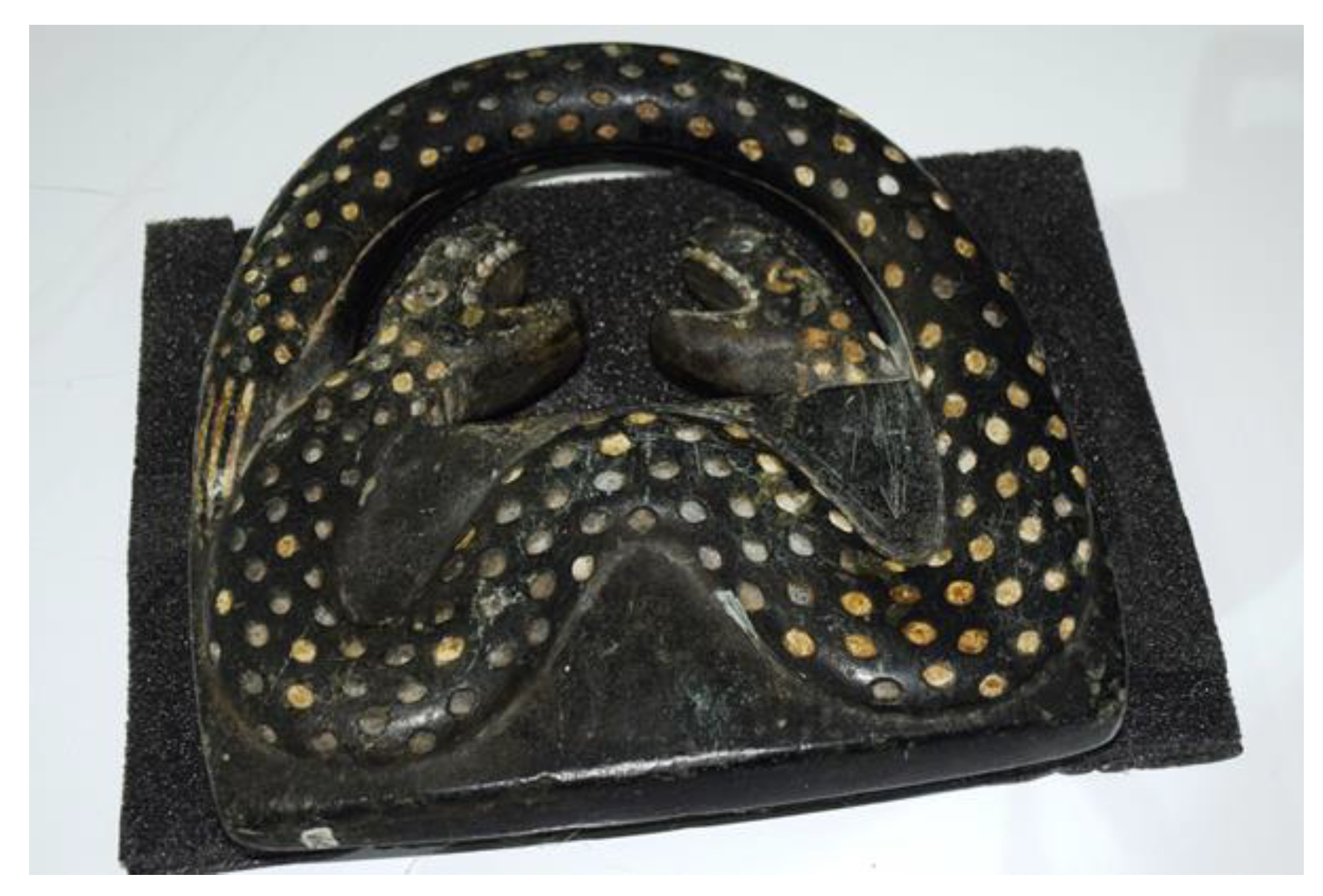
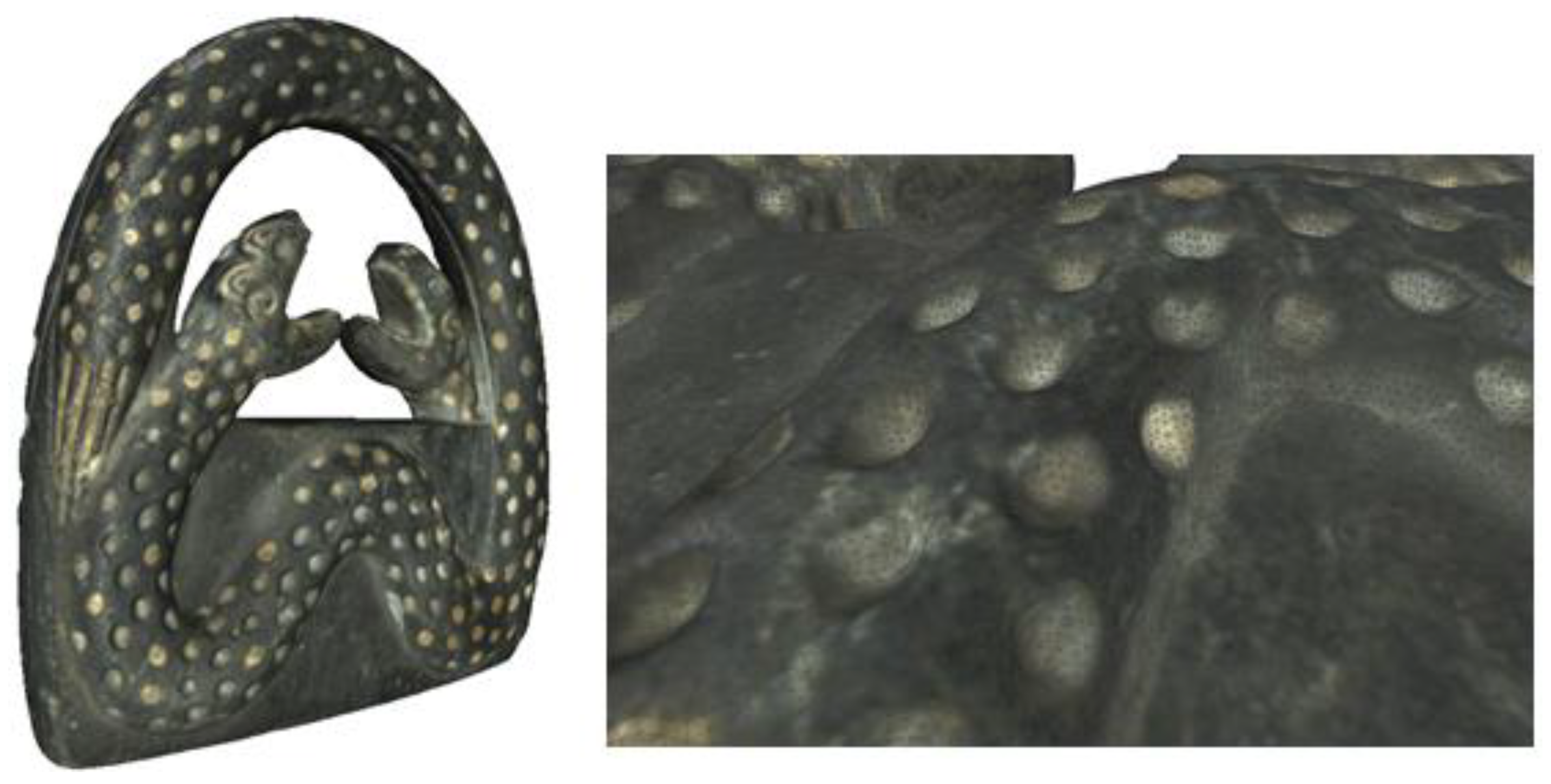
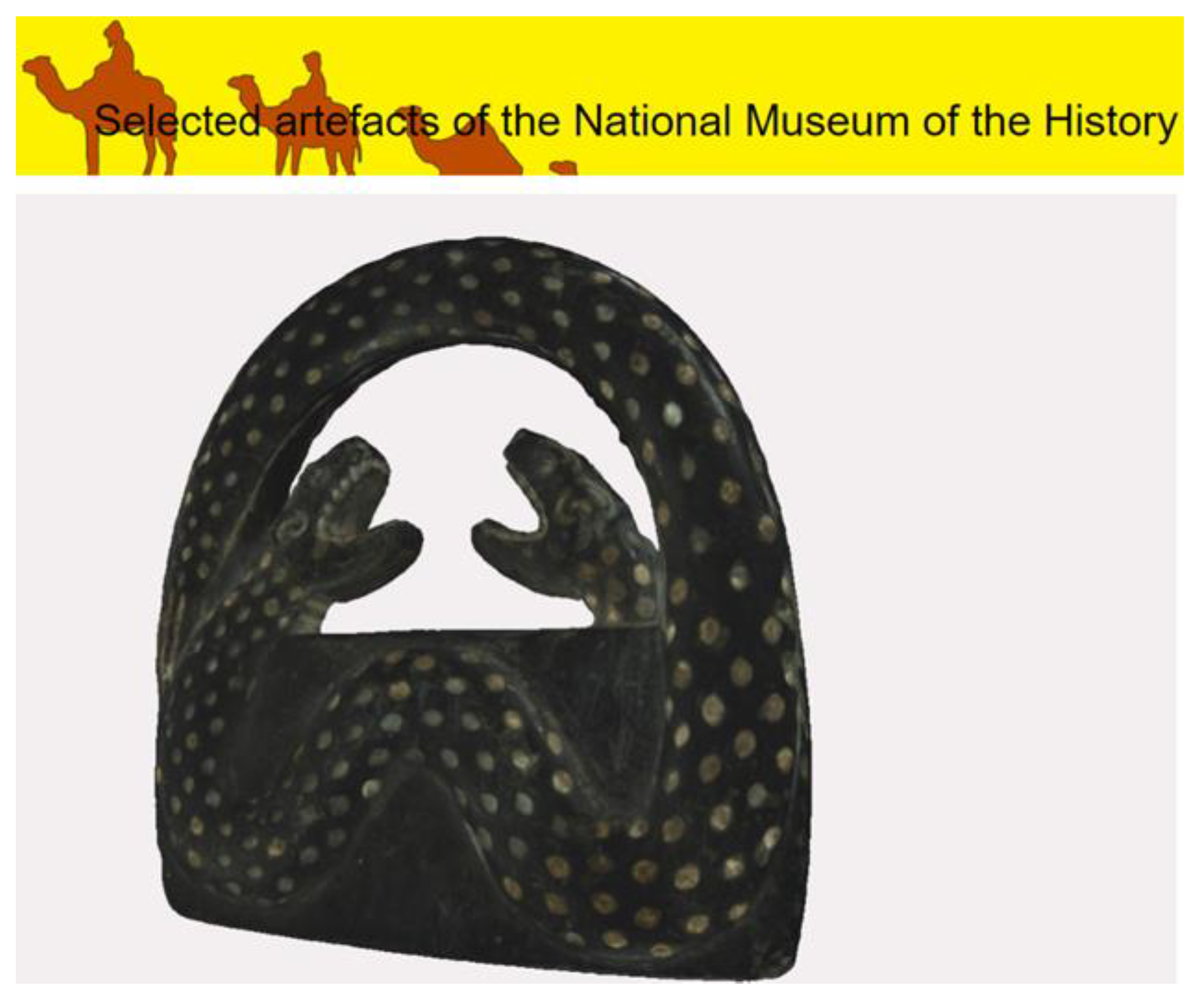
4.3.1. Case Study 1—“Snake”

Case study 1 concerns the heritage object called “Snake”, which belongs to the collection exhibited by the State Museum of the History of Uzbekistan in Tashkent. This is a type A object of the highest level of accessibility. It was scanned using the 3DScaMOTO method during one of the scientific expeditions of the Lublin University of Technology to Central Asia.
“Snake” is a figure depicting two snakes (Figure 2). It is made of polished stone, and its size is 26.3 × 23.6 × 4.4 cm. Due to the relatively small size and weight as well as quite compact construction, the museum authorities agreed to temporarily move the object to an ad hoc scanning site (Figure 3). As a result, the object could be placed on a soft foam in an area of good lighting. The procedure of moving and returning the object was carried out by employees of the museum and each time took about 10 min. The scanning process lasted 20 min, during which nine partial scans of both sides of the object were made. Data processing leading to the high-quality textured 3D mesh model took 2.5 h. The dissemination model, satisfactory in terms of quality and performance ratio, was obtained after 1 h.

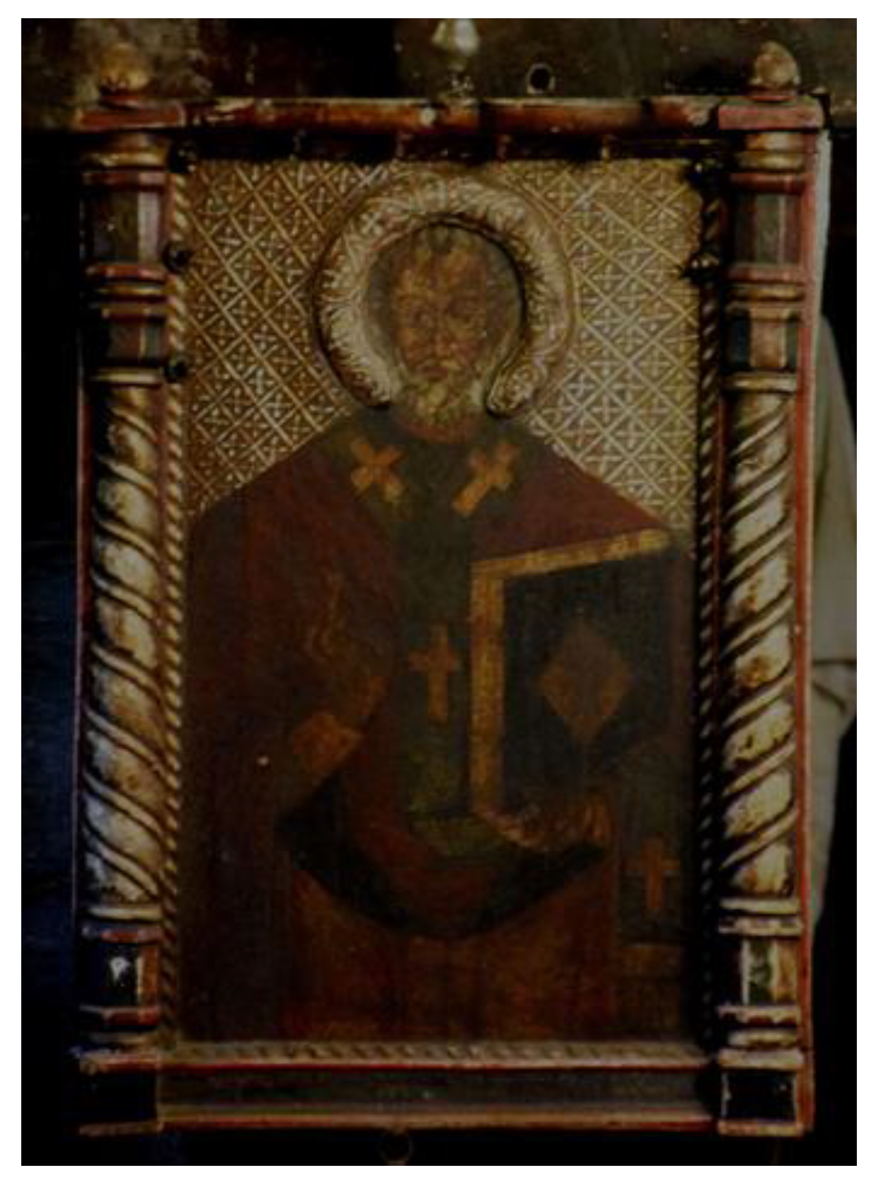
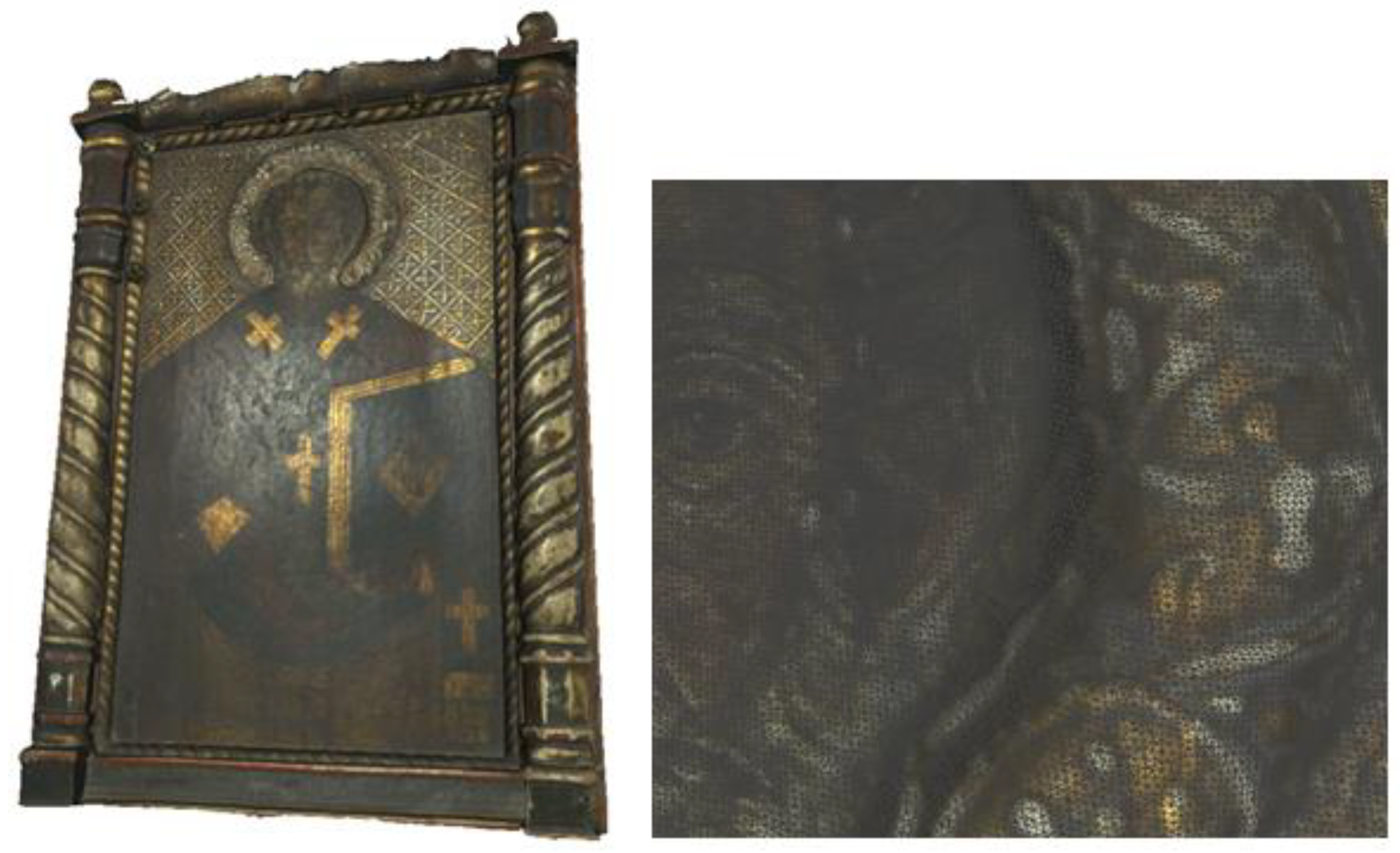
4.3.2. Case Study 2—“Icon of Saint Nicholas of Myra”

The icon of Saint Nicholas of Myra (Figure 4) is an example of the freely accessible but unmovable item. It is fixed to the wall of the orthodox church in Păușa, Romania. This wooden church was built in 1730 on a rectangular plan and restored in 1966–1968. The colorful interior paintings were made in 1800, probably by Ioan Pop from Ungurasi. Saint Nicholas, also known as Nicholas of Bari, is a saint of both the Catholic and Orthodox churches, who lived at the turn of the 3rd and 4th century and was the bishop of Myra. The icon, probably dating from the mid-18th century, is inside a wooden frame with the motif of twisted columns. A characteristic element is a wooden convex halo and gilded carved crosses arranged in diagonal coffers [38]. It was scanned using the 3DScaMOTO method during The First Scientific Expedition of the Lublin University of Technology to the Maramures region.
Due to the missing information regarding the icon’s vulnerability to strong light, the natural lighting of the church was utilized while scanning. As a result, exposure to excessive light produced by photographic lamps was avoided. The scanning process lasted 12 min, during which four partial scans of the icon’s front side were made. The icon was fixed to the wall; thus its back side was not scanned. It was considered then as a non-mandatory activity. The scanning site did not have to be restored to the original shape, and nothing was moved from the original place. Data processing leading to the high-quality textured 3D mesh model took 1.5 h. The dissemination model, satisfactory in terms of quality and performance ratio, was obtained after 1 h.

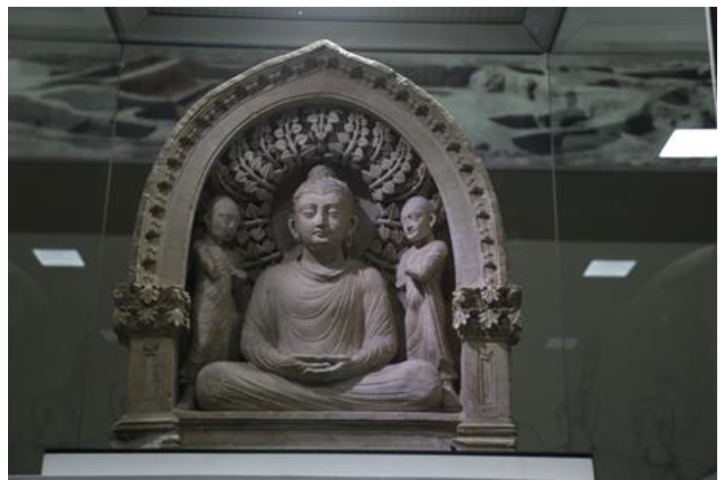
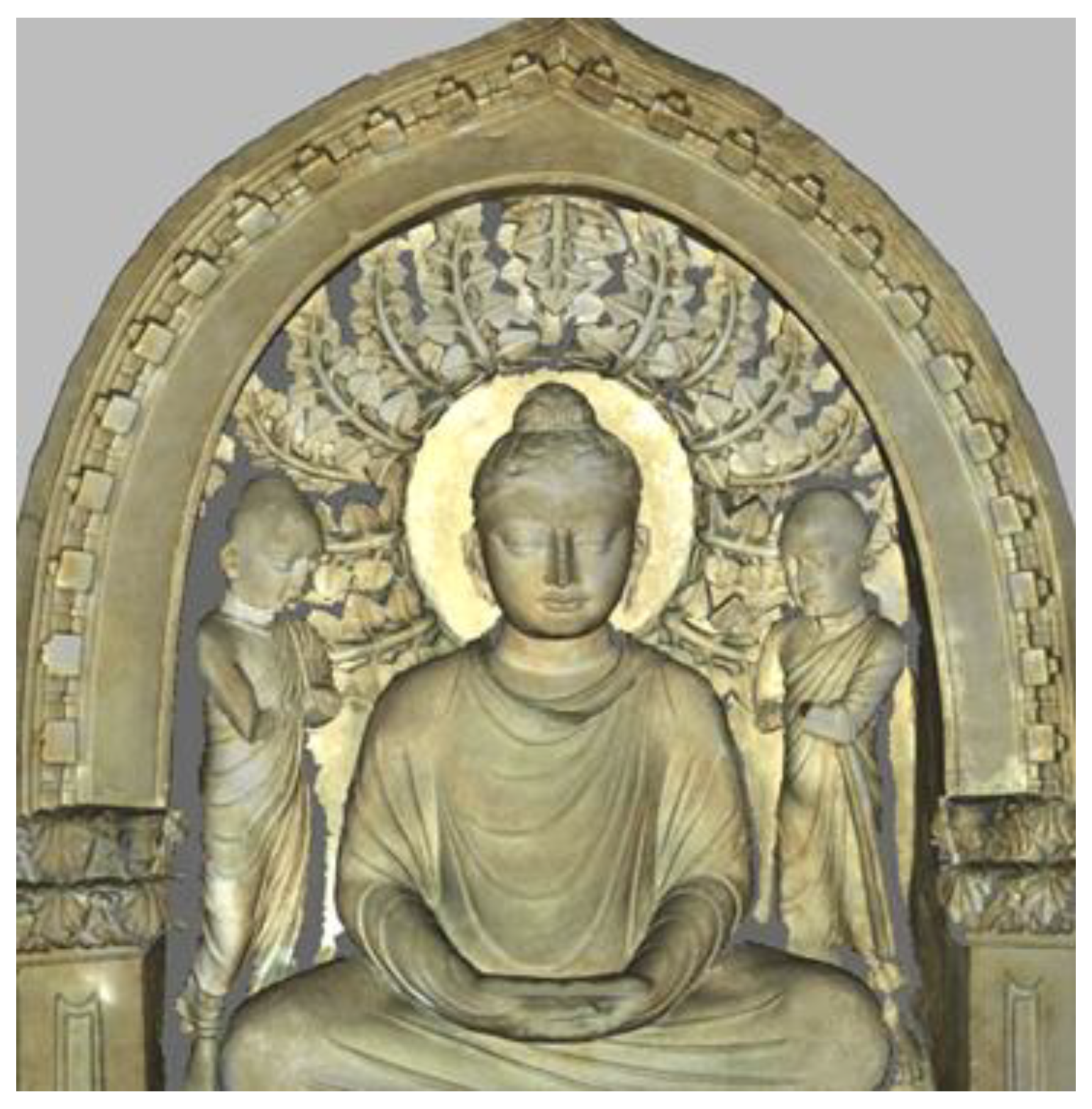
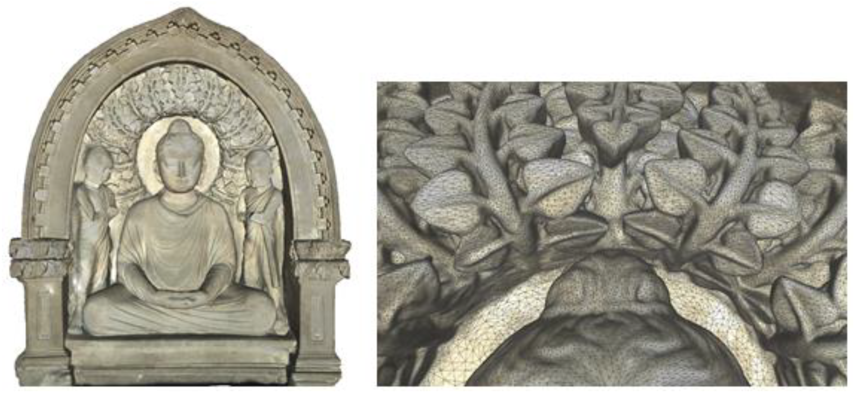
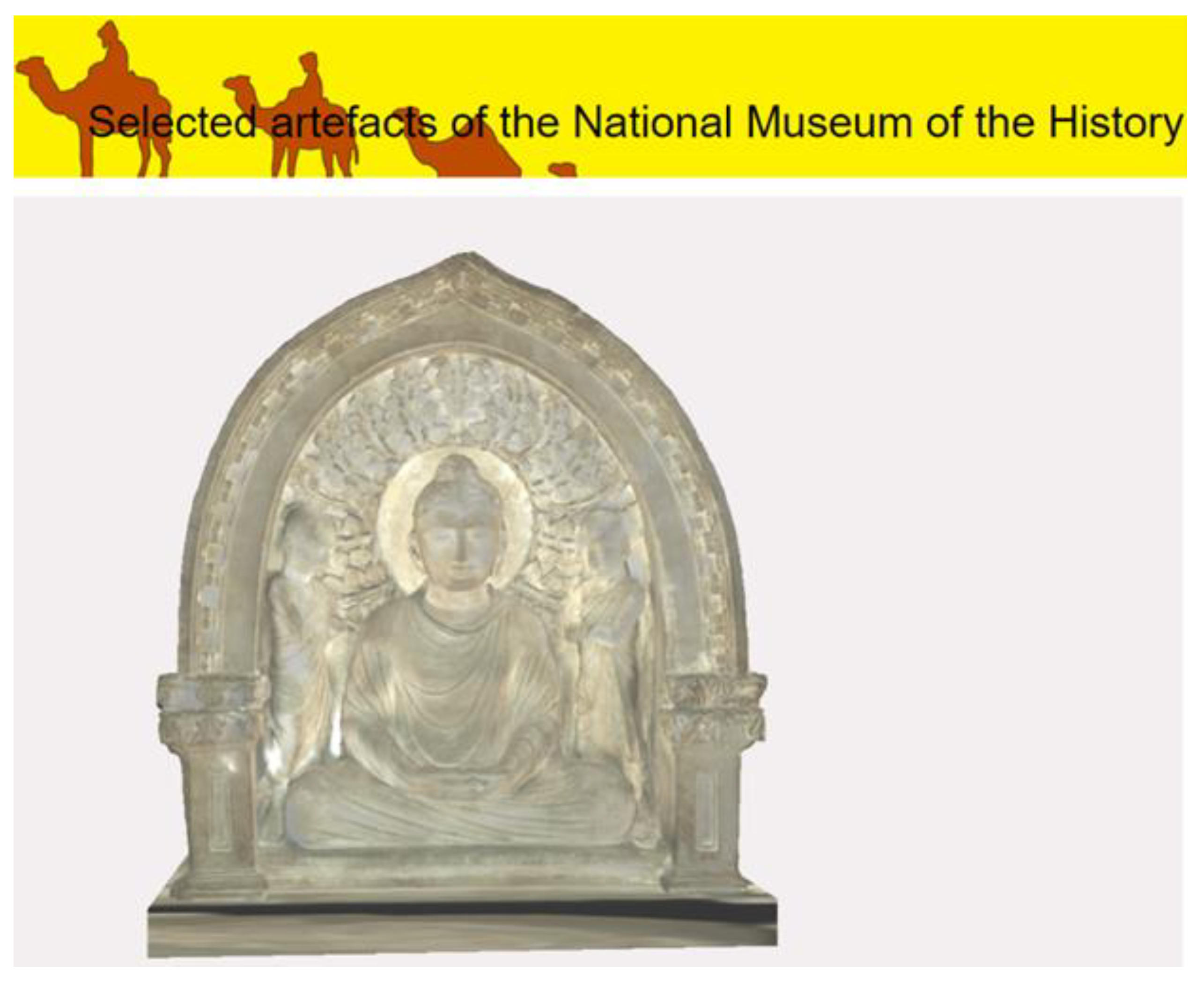
4.3.3. Case Study 3—“Buddha”

Case study 3 concerns the heritage object called “Buddha”, which belongs to the collection exhibited by the State Museum of the History of Uzbekistan in Tashkent. This is a type C object of low level of accessibility. It was scanned using the 3DScaMOTO method during one of the scientific expeditions of the Lublin University of Technology to Central Asia.
The object is a statue (sculpture) depicting Buddha, sitting in a pose of peace and spiritual harmony under the sacred Bodhi tree, and two monks standing on either side (Figure 5). The statue size is 74.6 × 65.9 × 29.6 cm. It is a most valuable finding from the Fayaztepa complex (Uzbekistan) that was discovered in 1963. The sculpture, carved in limestone and gilded, dates from the 1st century AD. Today, this sculptural composition is one of the most valuable exhibits of the State Museum of the History of Uzbekistan in Tashkent.
The statue is standing on a pedestal in a display case with glass walls. Access to the statue is possible by opening the side wall on the right side (Figure 6). The statue is too heavy to be easily removed from the display case. During the planning stage, it was estimated that the front glass of the display case was located at a distance from the statue’s surface allowing for a 3D scanner to be placed inside. There was also free access to the right side of the statue after opening the display case. The panes on the left side and on the back of the statue were too close to the object for a scanner to be placed inside. The Artec Eva scanner was able to scan the statue’s front with satisfactory accuracy, but there was a risk of not being able to scan deep, narrow grooves and internal fragments of the statue due to the dimensions and working distance of the scanner. Additionally, scanning through the glass might have introduced some errors, despite being possible for structured light scanners.
Finally, after consultations with the museum, it was decided to 3D scan the statue’s front from the inside of the display case in order to ensure good-quality archiving of the shape of the statue’s most valuable parts. In the case of other parts, as of quite simple shape and texture, they were scanned through the glass. Then, the scanning stage was executed. Preparation of the scanning site, including opening the display case, took 10 min. The scanning process itself took 45 min. As a result, 20 partial scans were collected in total: 15 scans of the statue’s front carried out directly and 5 scans carried out through the glass. After another 15 min, the display case was restored to its original condition. Data processing leading to the high-quality textured 3D mesh model took 5.3 h. The dissemination model, satisfactory in terms of quality and performance ratio, was obtained after 1.2 h.

4.4. Hardware and Software

The scanning was carried out using a hand-held structured-light Artec EVA 3D scanner, providing 50–100 microns accuracy and saving textures. Photographic documentation was made using a Nikon D7200 digital camera. In the case of several scans of the “Snake” figure, a rotary table with a surface texture was used to facilitate the positioning of the scanner.
The software used to obtain both base and dissemination models was Artec Studio Professional, Blender and MeshLab. Artec Studio was especially important during the scanning and the first phases of scans processing, as a software dedicated for the Artec EVA 3D scanner. The remaining programs were used to process 3D models and export them in proper quality.
Computations were performed on a laptop equipped with i9-9900K processor, 64 GB RAM, RTX 2080 8GB graphics card and 2TB SSD. Using a less powerful computer is still possible, although the time of computations strongly depends on the CPU and availability of sufficient memory to keep the object’s data loaded. Data gathering could also be assisted by a MicroSoft Surface tablet—the main advantages are improving portability and easing operation of the whole setup.

5. Results and Discussion

The results of 3D scanning, according to the presented procedure, aggregated for all case studies, are presented in Table 2. The size of a 3D model is provided in MB and thousands of triangles—K stands for thousands and Tri stands for triangles. The processing time is the sum of obtaining 3D base model time and obtaining 3D dissemination model time. Preparation time concerns the time needed to prepare a heritage object for scanning. Restoring time concerns the time needed to restore a heritage site to the condition before preparation for scanning. Discussion on procedure, problems and solutions, in the context of each case study, is presented in the subsequent sections.

5.1. Case Study 1—“Snake”

In the case of the “Snake” figure, the scanning time was 20 min. During this time, 9 partial scans of both sides of the figure were made. The number of partial scans was dictated by the need to increase the repeatability of scans due to the “difficult” surface of the object—glossy black stone with a small number of characteristic areas. Dealing with this challenge required maintaining a relatively uniform distance between the scanner and the object surface. Expecting the occurrence of glare and breaks in the scanned surface, the scanning of each figure side was repeated several times.
During the data processing stage, the obtained partial scans underwent processing and assessment. It lasted 2.5 h. As a result, one scan of unsatisfactory quality was rejected due to the occurrence of significant gaps and visible reflections on the saved texture. The remaining 8 scans were used to generate the high-quality base 3D model (Figure 7—on the left). The obtained model covered 100% of the “Snake” figure area—there were no areas that could not be digitized. The obtained mesh density allowed for a good reproduction of the object’s shape and cavities (Figure 7—on the right).
It took another 1 h to prepare the dissemination 3D model (Figure 8) for the purpose of publishing it on the 3D Digital Silk Road Portal [39]. The time spent is mainly the result of finding a balance between the model quality and providing fair performance for the viewers. The performance aspect was very important as the model was published within a larger collection on a website offering a dedicated 3D viewer. Other actions concerned polishing, converting and publishing the model to meet the requirements of the portal.
It was the simplest of the use cases. It can be seen from the shortest preparation, scanning and restoration times, which were no longer than 20 min. Due to the small dimensions and simple shape, the size of scans was the smallest, just as the processing time leading to the 3D base model. To conclude, in this case, the applied methodology turned out to be fully sufficient.

5.2. Case Study 2—“Icon of Saint Nicholas of Myra”

The icon was attached to the wall of the church main hall. During the accessibility assessment stage, the risk of moving the icon was evaluated as too high to be undertaken, thus it was decided to scan the icon from the front. It was possible without removing elements of the church’s decor. The church administrators had no information about possible light sensitivity of the icon. Therefore, it was assumed that the permissible intensity of light cannot exceed the intensity of the church’s own lighting. Scanning was carried out with the scanner’s own lighting turned off. It turned out that such conditions were enough to obtain a satisfactory color of the texture. During the 12 min scan, four partial scans of the icon’s surface and borders were obtained. Due to the variety of textures and colors, no repetition of scans was required.
The processing stage confirmed the good quality of the obtained scans—all four scans were accepted and used in generation of the base model. (Figure 9—on the left). It lasted 1.5 h. The obtained base model is a representation of the icon’s front part, which is the area of greatest importance. Despite the fact that only ~50% of the original object was scanned, it was sufficient for the object analysis and presentation. The back of the icon, assuming negligible or low historical value of its surface, could be digitally reconstructed, e.g., by means of CAD software. The obtained grid density and colors (Figure 9—on the right) allow for a good reproduction of the icon’s surface appearance and texture. The dissemination model shows some discontinuities in the area of the upper frame (Figure 10), which are more strongly emphasized due to significant simplification of the 3D model mesh.
The less-than-perfect lighting conditions during the 3D scanning, chosen due to uncertainty about the icon vulnerability to strong lighting, triggered that the obtained final 3D model might slightly differ from the original in terms of colors. Nevertheless, the use of the 3DScaMOTO method allowed for creation of an acceptable base model (for archiving purposes) and a good dissemination model, while not exposing the object to unnecessary harm.

5.3. Case Study 3—“Buddha”

The surface of the statue with a uniform, non-glossy texture (limestone) made it possible to perform 3D scanning from the minimum allowable distance. It was important due to the limited space inside the display case.
Three dimensional scanning of the statue lasted 45 min in total. It took 35 min to scan the statue’s front. 15 scans were made with different orientation and trajectory of the scanner in relation to the object. The aim was to obtain the fullest possible scan of the deep grooves (especially in the area depicting leaves of a Bodhi tree). In addition, five scans of the statue’s rear surface were made, using the scanner placed outside the display case. Scanning that part took 10 min. Despite many attempts to scan with different scanner settings, it was impossible to perform a complete scan of the statue’s front part—as expected (Figure 11).
The side walls of the grooves in the area of a Bodhi tree leaves and the grooves around the monks have not been completely digitized. The problem here was not so much limited access to the object due to the display case, but the shape of the grooves: narrow, deep gaps smaller than the dimensions of the scanner. It was not possible to position the scanner so that it could properly see the problematic surfaces of the grooves with all its cameras. The statue’s rear part, despite scanning through the glass, did not show similar problems (mainly due to a fairly uniform surface without major depressions and gaps). The scan matching process did not reveal any significant deformations due to potential interference while scanning through the glass.
During the data processing stage, the obtained partial scans underwent processing and assessment, which lasted 5.3 h. As a result, two scans of unsatisfactory quality were rejected. The remaining 18 scans were used to generate the high-quality base 3D model (Figure 12—on the left). It was estimated that the obtained model covered 85% of the original “Buddha” statue. Luckily, the obtained fragmentary scans of Bodhi tree leaves turned out to be sufficient to apply the algorithms for filling gaps in the meshes of triangles, obtaining the effect visually similar to the original (Figure 12—on the right). A similar situation took place in the areas around the monks, although this time the deviation from the original is more evident. Nevertheless, it was possible to obtain a complete 3D model of the statue, reproducing the original sufficiently in terms of shape and color—which was the main purpose of the scan (Figure 12—on the left).
It took another 1.2 h to prepare the dissemination 3D model (Figure 13) for the purpose of publishing it on the 3D Digital Silk Road Portal [39]—similarly as in the case of the “Snake” figure. Again, the time spent is mainly the result of finding a balance between the model quality and mesh complexity, thus providing fair performance for the viewers. Although this time the mesh was noticeably more complex.
It was the most complicated of the cases used. It can be seen from the long preparing, scanning and restoring times that lasted 70 min in total. Due to the dimensions, hard accessibility and troublesome shape of the surface influencing the scanning approach, the size of scans was large, just as the processing time leading to the 3D base model. To conclude, in this case, the methodology applied was verified successfully, despite the final model not fully complying with the original heritage object.

6. Conclusions

Existing methodological approaches to 3D scanning of tangible heritage in most cases assume that the procedure of scanning is performed in places that are closed to tourists, at least for the time of scanning. However, closing an exhibition for tourists, or moving an artifact to be scanned, is not always possible.
The authors in this work proposed a methodological approach designed especially for small- and-medium sized objects to overcome difficulties expected in such cases. The procedure has been successfully implemented during the 3D scanning of objects of the Silk Road heritage as well as the wooden sacral architecture of the Maramures region. The authors provided three case studies, presenting different kinds of challenges, such as: an object being movable but of a glossy surface, an object being not movable but of good accessibility, at last an object being not movable and of bad accessibility. For each type of object, the procedural aspects were discussed, and the way from planning the scanning, through obtaining a 3D base model, to obtaining a 3D dissemination model was shown.
According to the authors, the research question posed in this work might be answered in the following way: “YES, it is possible to acquire, in an effective way, 3D scans using 3D scanners, specifically based on structured light, of historical objects while not removing these objects from their original area of exhibition.”. This assumption is based on long-term experience of the authors in applying the proposed methodological approach, its implementation during the presented case studies and above all due to its results of use.
It was revealed that the proposed procedure successfully allowed to counteract organizational problems during 3D scanning of heritage objects being under continuous display, and that the achieved results of scanning were nevertheless of good quality. In the case of the “Snake” figure, while applying the method, the goals of digitization were fully achieved. In the case of the “Buddha” statue, the digitization outcome’s deficiencies were not caused by the shortcomings of the method itself, but by limitations of the equipment used. Filling gaps in the dissemination model, and leaving gaps in the base model, might be the temporary solution. The case of the “Icon of Saint Nicholas of Myra” is similar, the difference lying in the need of CAD-like reconstruction of the icon’s back, due to the inability to move it from the church wall.
What is more, based on the authors’ experience it could be concluded that:
  • Digitization using a hand-held structured-light 3D scanner is quite a simple process, that could be performed on heritage sites without the need of providing extensive facilitation for the scanning persons.
  • Digitization using structured-light technology is safe for heritage objects, as there is no need for sticking markers on the object’s surface, as well as the objects are not warmed up thanks to the technology being low energy.
  • The 3D scanning technology described in this work, allows to capture photorealistic textures. As a result, the photographic documentation made by a digital camera does not have to be transformed to 3D model textures. The time and effort during postprocessing are saved.
  • High precision of scans allows the creation of high-quality 3D models for the heritage object archaization purposes. Such models might later be used, e.g., for reconstruction purposes, as dimensions of the original object might be read from them. Such models might also be adjusted according to dissemination purposes.
Further works concerning 3D digitization of heritage objects being under continuous display will be conducted in compliance with the method presented in this work. This should further verify the method and be the source of valuable insights for the method modifications.

Author Contributions

Conceptualization, J.K. and K.Ż.; methodology, J.K., M.M., K.Ż. and J.M.; software, J.K.; validation, J.K., M.M., J.M., M.J. and C.N.; formal analysis, K.Ż. and J.K.; investigation, J.K., K.Ż., M.M. and J.M.; resources, J.K., J.M., M.J. and C.N.; data curation, J.K., M.M. and M.J.; writing—original draft preparation, K.Ż., J.K. and J.M.; writing—review and editing, K.Ż., M.J. and M.M.; visualization, K.Ż. and J.K.; supervision, J.K., M.M. and K.Ż.; project administration, M.M., K.Ż. and J.K.; funding acquisition, M.M. and J.M. All authors have read and agreed to the published version of the manuscript.

Funding

The APC was funded by the Lublin University of Technology Scientific Fund FD-22/IT-3/999.

Institutional Review Board Statement

Not applicable.

Informed Consent Statement

Not applicable.

Data Availability Statement

Not applicable.

Acknowledgments

The authors thank Jannat Ismailova (State Museum of History of Uzbekistan, Tashkent, Uzbekistan).

Conflicts of Interest

The authors declare no conflict of interest.

References

  1. New European Bauhaus. Available online: https://europa.eu/new-european-bauhaus/about/about-initiative_en (accessed on 9 September 2022).
  2. EREA-EU-Funded Cultural Heritage Projects. Available online: https://rea.ec.europa.eu/news/eu-funded-cultural-heritage-projects-2022-05-03_en (accessed on 9 September 2022).
  3. EREA-€264 Million Available to Finance Research on Cultural Heritage Preservation, Migrant Integration, Democracy and the Creative Industries. Available online: https://rea.ec.europa.eu/news/eu264-million-available-finance-research-cultural-heritage-preservation-migrant-integration-2022-01-20_en (accessed on 9 September 2022).
  4. UNDP-Social and Environmental Standards, Standard 4. Available online: https://info.undp.org/sites/bpps/SES_Toolkit/SitePages/Standard%204.aspx (accessed on 9 September 2022).
  5. Montusiewicz, J.; Miłosz, M.; Kęsik, J.; Żyła, K. Structured-light 3D scanning of exhibited historical clothing—A first-ever methodical trial and its results. Herit. Sci. 2021, 9, 74. [Google Scholar] [CrossRef]
  6. Miłosz, M.; Montusiewicz, J.; Kęsik, J.; Żyła, K.; Miłosz, E.; Kayumov, R.; Anvarov, N. Virtual scientific expedition for 3D scanning of museum artifacts in the COVID-19 period—The methodology and case study. Digit. Appl. Archaeol. Cult. Herit. 2022, 26, e00230. [Google Scholar] [CrossRef]
  7. Miłosz, M.; Skulimowski, S.; Kęsik, J.; Montusiewicz, J. Virtual and interactive museum of archaeological artefacts from Afrasiyab—An ancient city on the silk road. Digit. Appl. Archaeol. Cult. Herit. 2020, 18, e00155. [Google Scholar] [CrossRef]
  8. Skublewska-Paszkowska, M.; Powroźnik, P.; Smołka, J.; Miłosz, M.; Łukasik, E.; Mukhamedova, D.; Miłosz, E. Methodology of 3D scanning of intangible cultural heritage—The example of Lazgi dance. Appl. Sci. 2021, 11, 11568. [Google Scholar] [CrossRef]
  9. Żyła, K.; Kęsik, J.; Santos, F.; House, G. Scanning of historical clothes using 3D scanners: Comparison of goals, tools, and methods. Appl. Sci. 2021, 11, 5588. [Google Scholar] [CrossRef]
  10. Comes, R.; Neamțu, C.; Buna, Z.L.; Bodi, S.; Popescu, D.; Tompa, V.; Ghinea, R.; Mateescu-Suciu, L. Enhancing accessibility to cultural heritage through digital content and virtual reality: A case study of the Sarmizegetusa Regia UNESCO site. J. Anc. Hist. Archaeol. 2020, 7, 124–139. [Google Scholar] [CrossRef]
  11. Popovici, D.-M.; Iordache, D.; Comes, R.; Neamțu, C.G.D.; Băutu, E. Interactive exploration of virtual heritage by means of natural gestures. Appl. Sci. 2022, 12, 4452. [Google Scholar] [CrossRef]
  12. Gomes, L.; Regina, O.; Bellon, P.; Silva, L. 3D reconstruction methods for digital preservation of cultural heritage: A survey. Pattern Recognit. Lett. 2014, 50, 3–14. [Google Scholar] [CrossRef]
  13. Bruno, F.; Bruno, S.; De Sensi, G.; Luchi, M.-L.; Mancuso, S.; Muzzupappa, M. From 3D reconstruction to virtual reality: A complete methodology for digital archaeological exhibition. J. Cult. Herit. 2010, 11, 42–49. [Google Scholar] [CrossRef]
  14. Sampaio, A.Z.; Gomes, A.M.; Sánchez-Lite, A.; Zulueta, P.; González-Gaya, C. Analysis of BIM methodology applied to practical cases in the preservation of heritage buildings. Sustainability 2021, 13, 3129. [Google Scholar] [CrossRef]
  15. Pepe, M.; Costantino, D.; Alfio, V.S.; Restuccia, A.G.; Papalino, N.M. Scan to BIM for the digital management and representation in 3D GIS environment of cultural heritage site. J. Cult. Herit. 2021, 50, 115–125. [Google Scholar] [CrossRef]
  16. Miłosz, M.; Kęsik, J.; Montusiewicz, J. 3D scanning and visualization of large monuments of Timurid architecture in Central Asia—A methodical approach. J. Comput. Cult. Herit. 2021, 14, 1–31. [Google Scholar] [CrossRef]
  17. Daneshmand, M.; Helmi, A.; Avots, E.; Noroozi, F.; Alisinanoglu, F.; Arslan, H.S.; Gorbova, J.; Haamer, R.E.; Ozcinar, C.; Anbarjafari, G. 3D scanning: A comprehensive survey. arXiv 2018, arXiv:1801.08863v1. [Google Scholar] [CrossRef]
  18. Miłosz, M.; Montusiewicz, J.; Kęsik, J. 3D Information Technology in the Protection and Popularization of the Cultural Heritage of the Silk Road; Wydawnictwo Politechniki Lubelskiej: Lublin, Poland, 2022; ISBN 978-83-7947-521-6. Available online: http://bc.pollub.pl/dlibra/publication/14114/edition/13771 (accessed on 9 November 2022).
  19. Montusiewicz, J.; Czyż, Z.; Kayumov, R. Selected methods of making three—Dimensional virtual models of museum ceramic objects. Appl. Comput. Sci. 2015, 11, 51–65. [Google Scholar]
  20. Kowalski, M.; Naruniec, J.; Daniluk, M. LiveScan3D: A fast and inexpensive 3D data acquisition system for multiple Kinect v2 sensors. In Proceedings of the 2015 International Conference on 3D Vision, Lyon, France, 19–22 October 2015. [Google Scholar] [CrossRef]
  21. Tucci, G.; Bonora, V.; Conti, A.; Fiorini, L. High-quality 3D models and their use in a cultural heritage conservation project. Int. Arch. Photogramm. Remote Sens. Spat. Inf. Sci. 2017, XLII-2/W5, 687–693. [Google Scholar] [CrossRef] [Green Version]
  22. Ciekanowska, A.; Kiszczak-Gliński, A.; Dziedzic, K. Comparative analysis of Unity and Unreal Engine efficiency in creating virtual exhibitions of 3D scanned models. J. Comput. Sci. Inst. 2021, 20, 247–253. [Google Scholar] [CrossRef]
  23. Salwierz, A.; Szymczyk, T. Methods of creating realistic spaces—3D scanning and 3D modelling. J. Comput. Sci. Inst. 2020, 14, 101–108. [Google Scholar] [CrossRef]
  24. Akça, D.; Grün, A.; Breuckmann, B.; Lahanier, C. High definition 3D-scanning of arts objects and paintings. In Proceedings of the Optical 3-D Measurement VIII, Zurich, Switzerland, 9–12 July 2007; Volume II, pp. 50–58. [Google Scholar]
  25. Wei, O.C.; Chin, C.S.; Majid, Z.; Setan, H. 3D documentation and preservation of historical monument using terrestrial laser scanning. Geoinf. Sci. J. 2010, 10, 73–90. [Google Scholar]
  26. Neamtu, C.; Comes, R.; Popescu, D. Methodology to create digital and virtual 3D artefacts in archaeology. J. Anc. Hist. Archeol. 2016, 3, 65–74. [Google Scholar] [CrossRef] [Green Version]
  27. Bianco, G.; Gallo, A.; Bruno, F.; Muzzupappa, M. A comparison between active and passive techniques for underwater 3D applications. Int. Arch. Photogramm. Remote Sens. Spat. Inf. Sci. 2011, XXXVIII-5/W16, 357–363. [Google Scholar] [CrossRef] [Green Version]
  28. Bianco, S.; Ciocca, G.; Marelli, D. Evaluating the performance of structure from motion pipelines. J. Imaging 2018, 4, 98. [Google Scholar] [CrossRef]
  29. Barszcz, M.; Montusiewicz, J.; Paśnikowska-Łukaszuk, M.; Sałamacha, A. Comparative analysis of digital models of objects of cultural heritage obtained by the “3D SLS” and “SfM” methods. Appl. Sci. 2021, 11, 5321. [Google Scholar] [CrossRef]
  30. 3D Scanning of Exhibits from the County Museum in Nysa. Available online: https://global3d.pl/en/module/psblog/module-psblog-blog?id=77 (accessed on 19 November 2022).
  31. Girelli, V.A.; Tini, M.A.; Dellapasqua, M.; Bitelli, G. High resolution 3D acquisition and modelling in cultural heritage knowledge and restoration projects: The survey of the Fountain of Neptune in Bologna. Int. Arch. Photogramm. Remote Sens. Spat. Inf. Sci. 2019, XLII-2/W11, 573–578. [Google Scholar] [CrossRef] [Green Version]
  32. Kęsik, J.; Miłosz, M.; Montusiewicz, J.; Samarov, K. Documenting the geometry of large architectural monuments using 3D scanning—The case of the dome of the Golden Mosque of the Tillya-Kori Madrasah in Samarkand. Digit. Appl. Archaeol. Cult. Herit. 2021, 22, e00199. [Google Scholar] [CrossRef]
  33. Kvítková, Z.; Petru, Z. Challenges of tourism management in cultural UNESCO sites in the V4 countries from sustainability perspective. In Proceedings of the 23rd International Conference on Environmental Economics, Policy and International Environmental Relations, Prague, Czech Republic, 25–26 November 2021; pp. 102–107, ISBN 978-80-7490-230-7. [Google Scholar]
  34. Kvítková, Z.; Petru, Z.; Houška, P.; Macáková, L. Impact of the inscription of the cultural landscape on the UNESCO list on tourism destination. In Proceedings of the 25th International Colloquium on Regional Sciences, Brno, Czech Republic, 22–24 June 2022; pp. 375–381. [Google Scholar] [CrossRef]
  35. Kvítková, Z.; Petru, Z.; Šauer, P. Sustainability in smaller UNESCO sites from the entrepreneurs’ perspective. In Proceedings of the Aktuální Problémy Cestovního Ruchu, Jihlava, Czech Republic, 2–3 March 2022; pp. 1–12. [Google Scholar]
  36. Šauer, P.; Dvořák, A.; Mildeová, S.; Mokrišová, J. Vyjádření užitku přírodního statku metodou podmíněného hodnocení: Případ snížení rizika záplav. Politická Ekon. 1998, 46, 412–426. [Google Scholar] [CrossRef]
  37. Sauer, P.; Fiala, P.; Dvorak, A.; Kolínsky, O. Coalition projects in wastewater treatment: The case of a drinking water reservoir in the Czech Republic. J. Environ. Prot. Ecol. 2015, 16, 1492–1501. [Google Scholar]
  38. Popa, A. Biserica de lemn din Păușa—Sălaj. Acta Musei Napoc. 1971, XVIII, 593–602. [Google Scholar]
  39. Silk Road 3D Portal—Home. Available online: https://silkroad3d.com (accessed on 9 November 2022).
  40. Silk Road 3D Portal—Selected artefacts of the National Museum of the History of Uzbekistan. Available online: https://silkroad3d.com/wp-content/web3DView/tashkent1/?desclang=EN (accessed on 9 November 2022).
Figure 1. 3D scanning under tourist traffic in Tashkent at the National Museum of the History of Uzbekistan.
Applsci 13 00441 g001
Figure 2. “Snake” figure in the State Museum of the History of Uzbekistan in Tashkent.
Applsci 13 00441 g002
Figure 3. Scanning environment arrangement to scan the “Snake” figure.
Applsci 13 00441 g003
Figure 4. The icon of Saint Nicholas of Myra in the orthodox church in Păușa, Romania.
Applsci 13 00441 g004
Figure 5. “Buddha” statue in the State Museum of the History of Uzbekistan in Tashkent.
Applsci 13 00441 g005
Figure 6. Scanning environment arrangement for scan the “Buddha” statue.
Applsci 13 00441 g006
Figure 7. 3D base model of the “Snake” figure: overview (on the left) and mesh visible (on the right).
Applsci 13 00441 g007
Figure 8. 3D dissemination model of the “Snake” figure [40].
Applsci 13 00441 g008
Figure 9. 3D base model of the “Icon of Saint Nicholas of Myra”: overview (on the left) and mesh visible (on the right).
Applsci 13 00441 g009
Figure 10. 3D dissemination model of the “Icon of Saint Nicholas of Myra”.
Applsci 13 00441 g010
Figure 11. Incomplete 3D scan of the “Buddha” statue.
Applsci 13 00441 g011
Figure 12. 3D base model of the “Buddha” statue: overview (on the left) and mesh visible (on the right).
Applsci 13 00441 g012
Figure 13. 3D dissemination model of the “Buddha” statue [40].
Applsci 13 00441 g013
Table 1. 3DScaMOTO—methodical approach description.
Stage NameSubstagesResults
1. Planning1.1. Strategic planning
1.1.1. Getting to know the site, objects and exhibitions
1.1.2. Selecting objects to scan
1.1.3. Acquiring information about selected objects
1.1.4. Dividing objects into groups A, B, C
1.1.5. Determining the order of scanning
List of objects to be scanned divided into groups (A, B, C) and a preliminary sequence of scanning
1.2. Initial planning
1.2.1. Selecting places for ad hoc studios
1.2.2. Determining conditions of B and C type object sites
1.2.3. Assessing feasibility of the scanning—rejection of the impossible
1.2.4. Redetermining and confirming the order of scanning
1.2.5. Setting naming conventions
Final list of objects
Initial order of scanning
1.3. On-site replanning
1.3.1. Identifying expected problems
1.3.2. Rearranging plan of the scanning
1.3.3. Marking problematic objects
Redefined order of scanning adjusted to the current on-site conditions
2. Scanning2.1. Setting-up an ad hoc scanning studio at an exhibition site, if type A objects presentScanning place for objects of type A
2.2. For each object of type A:
2.2.1. Moving an object to an ad hoc studio
2.2.2. Setting parameters of scanning
2.2.3. Performing a 3D scan
2.2.4. Checking the 3D scan quality
2.2.5. Marking the 3D scan as problematic (if any, go to 2.2.2)
2.2.6. Acquiring additional data
2.2.7. Returning the object to its original place
Files with scans data
Additional data (e.g., photographs, historical background, etc.)
2.3. For each object of type B:
2.3.1. Preparing an exhibition place of an object for scanning
2.3.2. Setting parameters of scanning
2.3.3. Performing a 3D scan
2.3.4. Checking the 3D scan quality
2.3.5. Marking the 3D scan as problematic (if any, go to 2.3.2)
2.3.6. Acquiring additional data
2.3.7. Restoring the object’s exhibition site to its normal condition
Files with scans data
Additional data (e.g., photographs, historical background, etc.)
2.4. For each object of type C:
2.4.1. Preparing an exhibition place of an object for scanning
2.4.2. Setting parameters of scanning
2.4.3. Performing a 3D scan
2.4.4. Checking the 3D scan quality and inconsistencies caused by limited access
2.4.5. Developing an alternative way of problematic areas scanning if necessary (if any, go to 2.4.2)
2.4.6. Acquiring additional data
2.4.7. Restoring the object’s exhibition site to its normal condition
Files with scans data
Additional data (e.g., photographs, historical background, etc.)
3. Processing data3.1. Preparing scans
3.1.1. Analyzing gathered data
3.1.2. Discarding unusable or failed scans
3.1.3. Confirming correctness of an object name and description
Scan data ready for processing
3.2. Full processing
3.2.1. Filtering and cleaning up data
3.2.2. Curing or removing problematic areas of partial scans
3.2.3. Aligning partial scans
3.2.4. Global-registering of point clouds
Final point cloud
3.3. Final mesh processing
3.3.1. Setting a processing region
3.3.2. Performing conversion
3.3.3. Cleaning-up and fixing of a resulting 3D model
3.3.4. Coloring of a 3D model surface
Base (high quality) 3D mesh model
4. Preparing for dissemination4.1. Preparing dissemination 3D model
4.1.1. Obtaining requirements for a dissemination 3D model
4.1.2. Converting a base 3D model to a dissemination model
4.1.3. Testing quality (go to 4.2 if needed)
4.1.4. Arranging a dissemination model in a viewing environment
4.1.5. Preparing/Finalizing a 3D model for distribution
Dissemination 3D model
Table 2. Results of 3D scanning for the case studies.
Case Study Number123
Object name“Snake”“Icon of Saint Nicholas of Myra”“Buddha”
Place of scanningTashkent, UzbekistanRomaniaTashkent, Uzbekistan
Scanning environmentAd hoc studioOn the siteOn the site
3D scanner usedArtec EvaArtec EvaArtec Eva
Scanned object typeABC
Scanned object dimensions26.3 × 23.6 × 4.4 cm87.1 × 64.9 × 3.7 cm74.6 × 65.9 × 29.6 cm
Partial scans number9420
Rejected scans number102
Raw scan total size0.98 GB0.38 GB5.28 GB
Scan average accuracy0.5 mm0.6 mm0.4 mm
Problems with obtaining color and textureNONONO
Object surface digitized100%~50%85%
3D base model size27.2 MB, 394.5 KTri150.5 MB, 1.03 MTri62.1 MB, 886.8 KTri
3D dissemination model size10.6 MB, 145.9 KTri25.1 MB 250 KTri10.9 MB, 150.7 KTri
Preparing time10 min10 min10 min
Scanning time20 min12 min45 min
Restoring time10 min-15 min
Processing time3.5 h1.5 h6.5 h
Obtaining 3D base model time2.5 h1.0 h5.3 h
Obtaining 3D dissemination model time1.0 h0.5 h1.2 h
Disclaimer/Publisher’s Note: The statements, opinions and data contained in all publications are solely those of the individual author(s) and contributor(s) and not of MDPI and/or the editor(s). MDPI and/or the editor(s) disclaim responsibility for any injury to people or property resulting from any ideas, methods, instructions or products referred to in the content.

