Communication

Effects of Imperfect Assembly and Magnetic Properties on the Three-Pole AMB System

1
Department of Mechanical Engineering and Advanced Institute of Manufacturing with High-Tech Innovations, National Chung Cheng University, Chiayi 621, Taiwan
2
Green Energy and Environment Research Laboratories, Industrial Technology Research Institute, Hsin-Chu 310, Taiwan
*
Author to whom correspondence should be addressed.
Appl. Sci. 2023, 13(1), 347; https://doi.org/10.3390/app13010347
Submission received: 19 November 2022 / Revised: 11 December 2022 / Accepted: 25 December 2022 / Published: 27 December 2022
(This article belongs to the Section Mechanical Engineering)

Abstract

:

Featured Application

Active magnetic bearings are very useful in devices requiring high speed or noncontact condition, such as high-speed air compressors, flywheel energy-storage systems, turbo-molecular pumps, etc.

Abstract

This study is concerned with a three-pole active magnetic bearing (AMB) system with assembly error and non-uniform flux distribution. The assembly error, which is the result of the misalignment of the back-up bearing and the stator of AMB, induces strong nonlinear uncertainty in the AMB dynamics. The non-uniform flux distribution, which is mainly due to non-uniform material properties, manufacturing errors, etc., makes the magnetic force model more complicated. A stable-levitation controller is designed in consideration of the above factors. The controller is designed using the method of feedback linearization and integral sliding mode control (ISMC). Both simulation and experimental results indicate that the rotor can be levitated to the center of the back-up bearing, verifying the effectiveness of the proposed stable-levitation controller.

1. Introduction

Active magnetic bearings (AMB) have attracted much attention for decades [1]. Compared to conventional bearings, the noncontact nature of AMB makes it possess many unique and important features, including being frictionless, no lubrication needed, low noise, and high speed. It can also be applied in extreme environments, such as very high or low pressure, very high or low temperature, vacuum, and zero gravity. Because of these features, AMB has found wide applications, for instance, in turbo-molecular pumps [2], high-speed air compressor [3,4], flywheel energy-storage systems [5,6], control-momentum wheels [7], printed electronics systems [8], and machine tools [9], etc.
Modelling and control are two important issues for AMB systems. The dynamic model of the AMB system should be established first, before the levitation controller can be designed. The magnetic force model is the core for the dynamic model of AMB. In general, the magnetic force is a function of the rotor displacements and coil currents. Depending on the design of an AMB system, the magnetic force model may be complicated. For a complicated AMB design (e.g., with complicated geometry), an analytical magnetic force model may not be available, and one has to resort to a numerical model using a finite element method [10], or an experimental model by calibration and system identification [11]. Consequently, the magnetic force model is usually full of uncertainties. If the AMB’s geometry and the coil-winding scheme are simple and standard, an analytical magnetic force model can be obtained using physical laws like Ampere’s law and the principle of virtual work [12]. However, the analytical magnetic force model is, in general, established under some assumptions, such as no magnetic saturation, neglecting magnetic hysteresis, and linear magnetic field. In practical applications, such assumptions may not be satisfied. As a result, the uncertainties are generally inevitable in the magnetic force model. In addition to the magnetic force model, the uncertainties in the AMB system can also come from several other sources, including sensor noise, external disturbances, manufacturing and assembly errors, and imperfect magnetic properties.
There have been many studies in the literature considering the uncertainty in an AMB system, such as sensor noise, un-modeled dynamics, magnetic saturation, etc. [13,14,15,16,17]. However, there are two factors that can exist in practical AMB applications but which are seldom studied. One is the assembly error. It is usually assumed that the back-up bearing and AMB are concentric at the steady state. In other words, the rotor will be stabilized at the center of the back-up bearing so that the air gap at each magnetic pole is the same. However, due to assembly errors, the center of the back-up bearing may be biased from the stator center. Another factor is the non-uniform magnetic properties among magnetic poles due to non-uniform material properties, manufacturing errors, etc., which will cause non-uniform flux distribution.
This study is concerned with the modeling issue and controller design for a 3-pole AMB system with these two factors. The 3-pole AMB system possesses many advantages over the commonly used 8-pole AMB system [18]. Firstly, for a 2-degrees-of-freedom (DOF) AMB system, only two power amplifiers are required, while the 8-pole AMB system needs 4 power amplifiers. Next, it does not need large bias current for the linearization of the magnetic force, leading to lower bias currents. In addition, it has more space for winding, sensor installation, and heat dissipation. Finally, the re-magnetization frequency of the 3-pole AMB system is half of that for the 8-pole one, implying lower eddy-current loss and hysteresis loss. In summary, the 3-pole AMB system can save more costs compared to the 8-pole configuration. The difficulties associated with the 3-pole system is that there exist strong magnetic coupling effects among the 3 magnetic poles. As a result, the magnetic force model is strongly nonlinear and cannot be linearized. There have been extensive studies on the modeling and controller design for the 3-pole AMB system [19,20]. In this paper, the effects of imperfect assembly and magnetic properties on the 3-pole AMB system will be discussed, which have never been studied in the literature. Due to these effects, the conventional magnetic force model of the 3-pole AMB system needs to be modified. These issues are more significant for the 3-pole AMB system since the magnetic fluxes among the magnetic poles are coupled and the magnetic force model is strongly nonlinear [12,18]. The dynamic model of a 3-pole AMB system with the two factors will be derived and a stable-levitation controller will be designed.

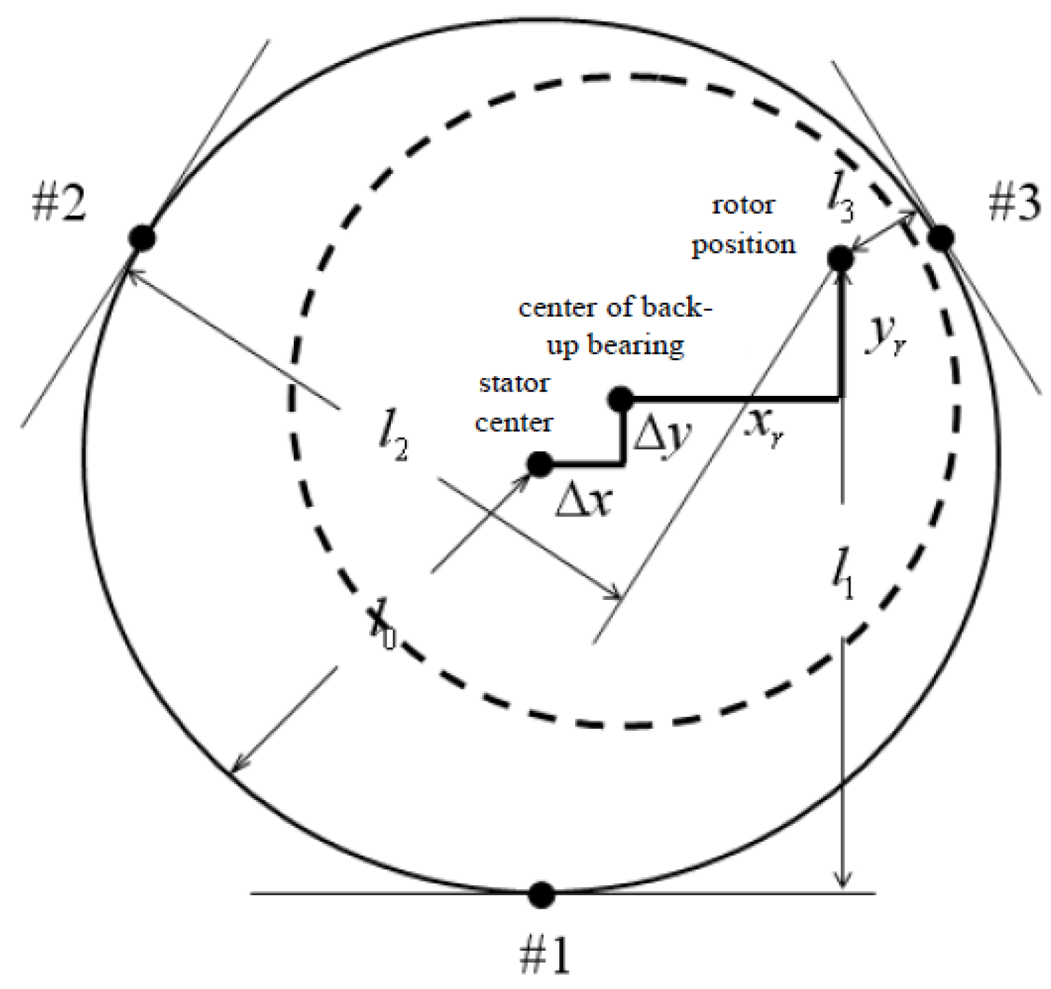
2. System Description and Dynamic Modeling

The system under study is the 3-pole AMB system shown in Figure 1. Figure 2 shows the relative position of the centers of the back-up bearing and stator. The dotted line indicates the allowable domain of the rotor motion. The AMB can provide magnetic forces in X and Y directions, supporting a 2-DOF disk-like rotor. It is assumed that the axial motion is constrained. The upper two magnetic poles share the same coil with opposite winding directions. The magnetic reluctances of the 3 air gaps between the rotor and the 3 magnetic poles are:
R 1 = 1 μ A ( l 0 + y r + Δ y ) ; R 2 = 1 μ A ( l 0 + 3 2 ( x r + Δ x ) 1 2 ( y r + Δ y ) ) R 3 = 1 μ A ( l 0 3 2 ( x r + Δ x ) 1 2 ( y r + Δ y ) )
where μ is the magnetic permeability of the air, A is the pole face area, l0 is the nominal air gap, (xr, yr) is the position of the rotor center, and Δ x , Δ y is the deviation of the back-up bearing center from the stator center. The origin of the inertial coordinate system is set to be the center of the back-up bearing since it can be easily calibrated. Next, we assume that ϕ i = k i ϕ ^ i , i = 1 ~ 3 , where ϕ i is the actual magnetic flux at each pole, ϕ ^ i is the theoretical magnetic flux based on the assumption of uniform magnetic properties, and k i represents the non-uniformity of the magnetic fluxes. The theoretical magnetic fluxes can be obtained from the magnetic circuit analysis as:
ϕ ^ 1 = N ( R 2 + R 3 ) i 1 + ( R 2 R 3 ) i 2 R 1 R 2 + R 2 R 3 + R 3 R 1
ϕ ^ 2 = N R 3 i 1 + ( 2 R 1 + R 3 ) i 2 R 1 R 2 + R 2 R 3 + R 3 R 1
ϕ ^ 3 = N R 2 i 1 ( 2 R 1 + R 2 ) i 2 R 1 R 2 + R 2 R 3 + R 3 R 1
where N is the number of coil turns on each magnetic pole and i 1 , i 2 are coil currents. Then, the dynamic model of the system is given by
x ¨ r = c 0 Φ 1 Φ 2 = c 0 Φ ^ 1 Φ ^ 2 + Δ f x ; y ¨ r = c 0 2 ( Φ 2 2 Φ 1 2 ) g = c 0 2 ( Φ ^ 2 2 Φ ^ 1 2 ) g + Δ f y
where c 0 = 4 μ A N 2 3 m , m is the rotor mass, and Φ 1 , Φ 2 are given by
Φ 1 = 3 4 μ A N ( ϕ 3 + ϕ 2 ) ; Φ 2 = 3 4 μ A N ( ϕ 3 ϕ 2 )
From (1) to (4), Φ 1 and Φ 2 can be expressed as
Φ 1 Φ 2 = 1 L K 2 l 0 ( y r + Δ y ) 3 ( x r + Δ x ) ( x r + Δ x ) 3 ( 2 l 0 + ( y r + Δ y ) ) i 1 i 2 ; K = 1 2 ( k 2 + k 3 ) 3 2 ( k 2 k 3 ) 3 6 ( k 2 k 3 ) 1 2 ( k 2 + k 3 )
where L = 4 l 0 2 [ ( x r + Δ x ) 2 + ( y r + Δ y ) 2 ] . Let L ^ = 4 l 0 2 ( x r 2 + y r 2 ) . Since, in general, Δ x , Δ y 0.1 l 0 , it is assumed that L ^ / L 1 . Then, in Equation (5), the nominal part of Φ 1 , Φ 2 is given by
Φ ^ 1 Φ ^ 2 = 1 L ^ K 2 l 0 y r 3 x r x r 3 ( 2 l 0 + y r ) i 1 i 2
and the uncertainty of magnetic forces caused by the effect of Δ x , Δ y is represented by Δ f x , Δ f y and is given by
Δ f x = c 0 ( Φ ^ 1 Δ Φ 2 + Φ ^ 2 Δ Φ 1 + Δ Φ 1 Δ Φ 2 ) c 0 ( Φ ^ 1 Δ Φ 2 + Φ ^ 2 Δ Φ 1 )
Δ f y = c 0 2 ( 2 Φ ^ 2 Δ Φ 2 + Δ Φ 2 2 2 Φ ^ 1 Δ Φ 1 Δ Φ 1 2 ) c 0 ( Φ ^ 2 Δ Φ 2 Φ ^ 1 Δ Φ 1 )
where Δ Φ 1 , Δ Φ 2 is the uncertain part of Φ 1 , Φ 2 , given by
Δ Φ 1 Δ Φ 2 = 1 L ^ K Δ y Δ x Δ x 3 Δ y i 1 i 2
Therefore, the dynamic Equation (5) can be represented in the state space form as
x ˙ = f ( x , i ) = x 2 c 0 Φ ^ 1 Φ ^ 2 x 4 c 0 2 ( Φ ^ 2 2 Φ ^ 1 2 ) g + 0 Δ f x 0 Δ f y
where x = [ x 1 x 2 x 3 x 4 ] T = [ x r x ˙ r y r y ˙ r ] T , i = [ i 1 i 2 ] T . In what follows, the stable levitation controller will be designed based on the nominal system under the influence of the uncertainty Δ f x , Δ f y .

3. Design of Stable-Levitation Controller

The stable-levitation controller will be designed using the method of feedback linearization and integral sliding mode control (ISMC) [19]. Note that the system (10) is a non-affine nonlinear system since the state equation depends on the control currents in a quadratic form. Fortunately, it is shown in [18] that the system is feedback linearizable with the control currents designed as
i 1 i 2 = 1 c 0 ( 2 l 0 + y r ) x r 1 3 x r 1 3 ( 2 l 0 y r ) K 1 ( i ˜ 2 + g ) + ( i ˜ 2 + g ) 2 + i ˜ 1 2 sgn ( i ˜ 1 ) ( i ˜ 2 + g ) + ( i ˜ 2 + g ) 2 + i ˜ 1 2
where i ˜ is the new control input to be designed and sgn is the sign function. The linearized system becomes
η ˙ = ξ ξ ˙ = i ˜ + Δ ( η , ξ , i ˜ )
where η = [ η 1 η 2 ] T = [ x 1 x 3 ] T , ξ = [ ξ 1 ξ 2 ] T = [ x 2 x 4 ] T , and Δ η , ξ , i ˜ = Δ x , i ˜ represents the uncertainty. To design ISMC for stabilization and robustness, the integral sliding manifold is first taken as
σ = ξ + b 1 η + b 2 z m z ˙ m = η
Then, the new control input is decomposed into two parts: the equivalent control and switching control, i.e., i ˜ = i ˜ e q + i ˜ s ; i ˜ e q = b 1 ξ b 2 η . With the equivalent control, the dynamics of the sliding variable is given by:
σ ˙ = i ˜ s + δ ( η , ξ , i ˜ s ) ; δ ( η , ξ , i ˜ s ) = Δ ( η , ξ , b 1 ξ b 2 η + i ˜ s )
It is assumed that the uncertainty is bounded by:
δ ( η , ξ , i ˜ s ) ρ + k i ˜ s
Finally, one can design the switching control using Lyapunov’s analysis and the overall control law will be:
i ˜ s = ρ + α 1 k sat ( σ ε ) i ˜ = b 1 ξ b 2 η ρ + α 1 k sat ( σ ε )
where b 1 , b 2 , ρ , k , α and ε are positive constants. In this paper, the uncertainty is mainly due to the assembly error given by (7) and (8). The upper bounds of its effect can be estimated. The ISMC controller is robust and can easily deal with such uncertainty. On the other hand, the non-uniform flux distribution is directly compensated using feedback linearization, as represented by the matrix K in Equation (11).

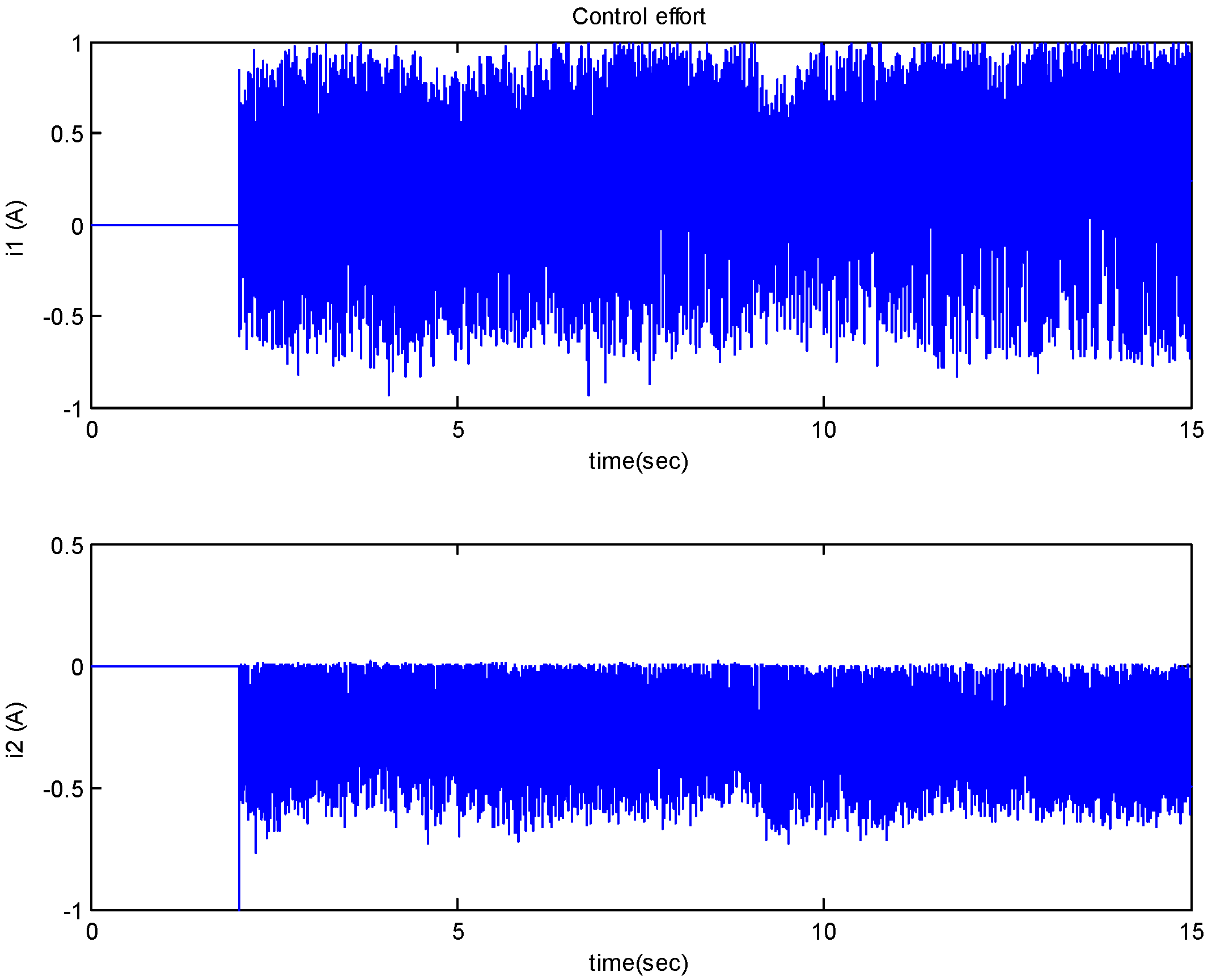
4. Simulation and Experimental Results

For numerical simulations and experimental validation, the system is shown in Figure 3, with parameters given by
m = 2.45 × 10 2   k g , g = 9.81   m / s 2 , μ = 4 π × 10 7   H / m , A = 3.6 × 10 5   m 2 , N = 350 , l 0 = 3 × 10 4   m
From calibration, we have k 1 = 0.763 , k 2 = 0.468 , k 3 = 0.905 , indicating the strong non-uniformity of the magnetic flux distributions. For simulations, it is assumed that Δ x = Δ y = 0.1 l 0 . Under such an assumption, it can be shown that Δ 0 . 75 i ˜ . The parameters of the ISMC controller are: ρ = 60 , k = 0.8 , α = 20 , ε = 0.01 , b 1 = 1 , b 2 = 5 . The rotor is initially at rest on the back-up bearing, i.e., the initial condition is x r ( 0 ) y r ( 0 ) = 0 1.528 × 10 4   m and x ˙ r ( 0 ) y ˙ r ( 0 ) = 0 0 . Figure 4 and Figure 5 show the simulation results, where the rotor trajectory is shown in Figure 4 and the rotor displacement responses are shown in Figure 5. As one can see, the rotor is first deviated a little bit to the right and overshoots to the upper position before settling down to the center eventually. This is due to the fact that we have assumed the assembly errors to be positive. Hence, the magnetic forces to the right and to the upper surface are larger since the air gaps are smaller.
For the experimental validation, the rotor displacements are measured by the laser displacement sensor of Keyence, LK-G35 with a resolution of 0.05   μ m . The power amplifier is made by Advanced Motion Control with Model 25A20. The controller is implemented using dSPACE’s DS 1103 motion-control card. The same control parameters as the simulation ones have been taken. To de-noise the measured signal, a Butterworth filter with bandwidth 600 Hz is taken:
H ( z ) = 0.0008 + 0.0032 z 1 + 0.0048 z 2 + 0.0032 z 3 + 0.0008 z 4 1 3.0176 z 1 + 3.5072 z 2 1.8476 z 3 + 0.3708 z 4
For the experimental results, the rotor trajectory is shown in Figure 6, and the steady-state rotor trajectory is shown in Figure 7. The rotor displacements are shown in Figure 8, and the control currents are shown in Figure 9. It should be note that the rotor is initially at rest on the back-up bearing and the levitation controller is activated at t = 2 s. It is clear that the performance is not as good as the simulation one, with longer settling time and larger steady state error of around 20 um. Recall that it is assumed that the assembly error is Δ x = Δ y = 0.1 l 0 for numerical simulations. However, the actual assembly error is unknown. Also, for the non-uniformity of the magnetic flux distributions, the parameters k 1 = 0.763 , k 2 = 0.468 , k 3 = 0.905 are taken in the simulations. These parameters were obtained by calibrations. Again, there must be some deviations from the actual parameters. Hence, Figure 8 (experimental response) cannot correspond to Figure 5 (simulation response).
In Figure 8, one can observe high frequency vibrations and some “irregularity” in the rotor response. The “irregularity” shown in Figure 8 is mostly in the transient period (before 15 s), which could be due to the un-modeled higher-order dynamics. As shown in Figure 7, the high-frequency vibrations at the steady state period (after 15 s) are confined within about 20 um, which are due to sensor noise. Thus, it is clear that the proposed controller can stably levitate the rotor with strong non-uniform flux distribution and assembly errors. This is also confirmed by the rotor trajectory shown in Figure 6. In summary, both simulation and experimental results indicate that the rotor can be levitated to the center of the back-up bearing. These results verify the effectiveness of the proposed stable-levitation controller.

5. Conclusions

A three-pole AMB system with assembly error and non-uniform flux distribution was considered in this study. The assembly error is caused by the misalignment of the back-up bearing and the stator of the AMB. The non-uniform flux distribution is mainly due to non-uniform material properties, manufacturing errors, etc. These factors induce the uncertainty that needs to be considered in the design of a stable-levitation controller. In this study, the stable-levitation controller has been designed using the method of feedback linearization and integral sliding mode control. The effect of the non-uniform flux distribution is included in the dynamic model and is directly compensated for by using feedback linearization. On the other hand, the effect of assembly errors is modeled as the uncertainty in the dynamic model. The resulting uncertain system has been stabilized using the robust controller designed by ISMC. The parameters of the ISMC controller depend on the uncertainty bounds that can be estimated using the magnetic force model. Both simulation and experimental results indicate that the rotor can be levitated to the center of the back-up bearing, verifying the effectiveness of the proposed stable-levitation controller.

Author Contributions

Conceptualization, S.-L.C.; methodology, S.-L.C.; software, Y.-T.L.; validation, Y.-T.L. and C.-H.L.; formal analysis, S.-L.C. and Y.-T.L.; investigation, Y.-T.L.; resources, S.-L.C.; data curation, C.-H.L.; writing—original draft preparation, S.-L.C. and Y.-T.L.; writing—review and editing, S.-L.C.; visualization, C.-H.L.; supervision, S.-L.C.; project administration, S.-L.C. and C.-Y.C.; funding acquisition, C.-Y.C. All authors have read and agreed to the published version of the manuscript.

Funding

This research was funded in part by the Advanced Institute of Manufacturing with High-tech Innovations (AIM-HI) from The Featured Areas Research Center Program within the framework of the Higher Education Sprout Project by the Ministry of Education (MOE) in Taiwan and was also supported in part by the Bureau of Energy, Ministry of Economic Affairs, Taiwan, R.O.C.

Institutional Review Board Statement

Not applicable.

Informed Consent Statement

Not applicable.

Conflicts of Interest

The authors declare no conflict of interest.

References

  1. Schweitzer, G.; Maslen, E.H. Magnetic Bearings: Theory, Design and Application to Rotating Machinery; Springer: Berlin, Germany, 2009. [Google Scholar]
  2. Bangcheng, H.; Zan, H.; Xu, Z.; Xu, L.; Tong, W.; Shiqiang, Z. Loss estimation, thermal analysis, and measurement of a large-scale turbomolecular pump with active magnetic bearings. IET Electr. Power Appl. 2020, 14, 1283–1290. [Google Scholar] [CrossRef]
  3. Prasad, K.N.V.; Narayanan, G. Electro-Magnetic Bearings with Power Electronic Control for High-Speed Rotating Machines: A Review. In Proceedings of the 2019 National Power Electronics Conference (NPEC), Tiruchirappalli, Tamil Nadu, India, 13–15 December 2019; pp. 1–6. [Google Scholar]
  4. Guan, X.; Zhou, J.; Jin, C.; Xu, Y.; Cui, H. Influence of different operating conditions on centrifugal compressor surge control with active magnetic bearings. Eng. Appl. Comput. Fluid Mech. 2019, 13, 824–832. [Google Scholar] [CrossRef] [Green Version]
  5. Toh, C.-S.; Chen, S.-L. Design, Modeling and Control of Magnetic Bearings for a Ring-Type Flywheel Energy Storage System. Energies 2016, 9, 1051. [Google Scholar] [CrossRef] [Green Version]
  6. Olabi, A.G.; Wilberforce, T.; Abdelkareem, M.A.; Ramadan, M. Critical Review of Flywheel Energy Storage System. Energies 2021, 14, 2159. [Google Scholar] [CrossRef]
  7. Wang, X.; Han, C.; Yu, Y.; Yang, Z. A modified adaptive backstepping method for shaft deflection tracking control of magnetically suspended momentum wheel with nonlinear magnetic torque. J. Frankl. Inst. 2018, 355, 3274–3287. [Google Scholar] [CrossRef]
  8. Park, C.H.; Yoon, T.G.; Kang, D.; Rodrigue, H. High-Precision Roller Supported by Active Magnetic Bearings. Appl. Sci. 2019, 9, 4389. [Google Scholar] [CrossRef] [Green Version]
  9. Lee, R.-M.; Chen, T.-C. Adaptive Control of Active Magnetic Bearing against Milling Dynamics. Appl. Sci. 2016, 6, 52. [Google Scholar] [CrossRef] [Green Version]
  10. Di, C.; Petrov, I.; Pyrhonen, J.J.; Bao, X. Unbalanced Magnetic Pull Compensation With Active Magnetic Bearings in a 2 MW High-Speed Induction Machine by FEM. IEEE Trans. Magn. 2018, 54, 1–13. [Google Scholar] [CrossRef]
  11. Chiu, H.-L. Identification Approach for Nonlinear MIMO Dynamics of Closed-Loop Active Magnetic Bearing System. Appl. Sci. 2022, 12, 8556. [Google Scholar] [CrossRef]
  12. Chen, S.L.; Hsu, C.T. Optimal Design of the 3-Pole Active Magnetic Bearing System. IEEE Trans. Magn. 2002, 38, 3458–3466. [Google Scholar] [CrossRef]
  13. El-Shourbagy, S.M.; Saeed, N.A.; Kamel, M.; Raslan, K.R.; Aboudaif, M.K.; Awrejcewicz, J. Control Performance, Stability Conditions, and Bifurcation Analysis of the Twelve-Pole Active Magnetic Bearings System. Appl. Sci. 2021, 11, 10839. [Google Scholar] [CrossRef]
  14. Giap, V.-N.; Huang, S.-C. Effectiveness of fuzzy sliding mode control boundary layer based on uncertainty and disturbance compensator on suspension active magnetic bearing system. Meas. Control 2020, 53, 934–942. [Google Scholar] [CrossRef] [Green Version]
  15. Yang, D.; Gao, X.; Cui, E.; Ma, Z. State-Constraints Adaptive Backstepping Control for Active Magnetic Bearings with Parameters Nonstationarities and Uncertainties. IEEE Trans. Ind. Electron. 2020, 68, 9822–9831. [Google Scholar] [CrossRef]
  16. Wang, S.; Zhu, H.; Wu, M.; Zhang, W. Active Disturbance Rejection Decoupling Control for Three-Degree-of- Freedom Six-Pole Active Magnetic Bearing Based on BP Neural Network. IEEE Trans. Appl. Supercond. 2020, 30, 1–5. [Google Scholar] [CrossRef]
  17. Saeed, N.A.; El-Shourbagy, S.M.; Kamel, M.; Raslan, K.R.; Awrejcewicz, J.; Gepreel, K.A. On the Resonant Vibrations Control of the Nonlinear Rotor Active Magnetic Bearing Systems. Appl. Sci. 2022, 12, 8300. [Google Scholar] [CrossRef]
  18. Hsu, C.-T.; Chen, S.-L. Nonlinear control of a 3-pole active magnetic bearing system. Automatica 2003, 39, 291–298. [Google Scholar] [CrossRef]
  19. Chen, S.-L.; Chen, S.-H.; Yan, S.-T. Experimental validation of a current-controlled three-pole magnetic rotor-bearing system. IEEE Trans. Magn. 2005, 41, 99–112. [Google Scholar] [CrossRef]
  20. Chen, S.L.; Lin, S.Y. Adaptive Unbalance Compensation for a Three-pole AMB System. IEEE Trans. Ind. Electron. 2020, 67, 2097–2106. [Google Scholar] [CrossRef]
Figure 1. The 3-pole AMB system.
Applsci 13 00347 g001
Figure 2. The rotor position with assembly error.
Applsci 13 00347 g002
Figure 3. The 3-pole AMB system under study.
Applsci 13 00347 g003
Figure 4. Simulation result: rotor trajectory.
Applsci 13 00347 g004
Figure 5. Simulation result: rotor displacement responses.
Applsci 13 00347 g005
Figure 6. Experimental result: rotor trajectory.
Applsci 13 00347 g006
Figure 7. Steady-state rotor trajectory.
Applsci 13 00347 g007
Figure 8. Experimental result: rotor-displacement responses.
Applsci 13 00347 g008
Figure 9. Experimental result: the control currents.
Applsci 13 00347 g009
Disclaimer/Publisher’s Note: The statements, opinions and data contained in all publications are solely those of the individual author(s) and contributor(s) and not of MDPI and/or the editor(s). MDPI and/or the editor(s) disclaim responsibility for any injury to people or property resulting from any ideas, methods, instructions or products referred to in the content.

