Article

Dynamics Analysis and Chaos Identification of Compound Pendulum Jaw Crusher with Joint Clearance

College of Mechanical and Automotive Engineering, Shanghai University of Engineering and Science, Shanghai 201620, China
*
Author to whom correspondence should be addressed.
Appl. Sci. 2023, 13(1), 238; https://doi.org/10.3390/app13010238
Submission received: 24 November 2022 / Revised: 20 December 2022 / Accepted: 23 December 2022 / Published: 24 December 2022

Abstract

:
A dynamic model of the working mechanism of a compound pendulum jaw crusher with clearance is established by the Lagrange multiplier method (LMD) based on the L-N contact force model and modified Coulomb friction force model. The correctness of the dynamic model is verified by MATLAB and Adams comparison simulation, and the best selection range of driving speed and clearance size is determined according to the laminating crushing theory (LCT). The effects of driving speed and clearance size on the shock and chaos phenomenon in the clearance mechanism are analyzed, as well as the vibration force applied to the foundation. The results show that, under the premise of meeting the requirements of crusher production capacity, increasing the driving speed and reducing the clearance size can weaken the shock and chaos phenomenon during the operation of the mechanism, improve the dynamic performance and enhance the operation stability, and the service life of foundation is prolonged with the stability of vibration force. Furthermore, the optimal combination of driving speed and clearance size is determined, which provides a theoretical basis for the optimization of the vibration force of the jaw crusher.

1. Introduction

Jaw crushers are utilized extensively in the industries of mining, metallurgy, building materials, ceramics, and engineering of massive minerals with small and medium particle size crushing [1,2,3]. There are now more demands on crushers in terms of efficiency, energy use, and cost due to new issues including the rise in low-quality ore, energy shortages, and the rising demand for building materials [4]. The frame will be subjected to the inertia force produced by the eccentric shaft, elbow plate, and other components when the crusher is operating, which will cause the crusher to vibrate and transfer to the fixed foundation of the crusher, reducing the service life of the foundation [5].
Research on the optimization of the crusher’s vibration force must be conducted in order to lower the failure rate of the machine and avoid equipment damage. Yang [6] established a parametric model of a jaw crusher using the ANSYS Parametric Design Language (APDL) and optimized the design with the minimum weight of a movable jaw as the objective function. This reduced the vibration caused by the inertia force of the working mechanism, improved the mechanism’s dynamic performance and extended the service life of the product. Li [7] proposed a vibrator–pendulum coupling system in which the pendulum is driven by the synchronous motion of the two vibrators directly. The synchronization criterion of the two vibrators and the stability criterion for the synchronous states were derived, allowing a new kind of vibration jaw crusher to be designed to work with its swing motion trajectory under the premise of stable zero-phase difference between the two vibrators. In order to create a more efficient dynamic balance mechanism, Cheng [8] established a real-time dynamic model of a crusher based on multi-body dynamics (MBD) and the discrete element method (DEM). Using the response surface method (RSM), the predictive regression model of crusher performance was constructed. The amplitude of vibration force was greatly decreased by increasing the mass of the fixed cone for optimization.
Current research on jaw crushers has concentrated on the design and optimization of the mechanism structure [9], ignoring the existence of joint clearance. When the crusher is operating at a high speed and under a heavy load, the revolute joint’s elements will lose contact with one another. When they come into contact again owing to constraint and inertia, a collision will happen. At this point, the revolute joint’s response force can be several times or even a dozen times as great as when there is no clearance [10], which invariably has an effect on the assessment of crusher vibration.
The dynamic performance of the clearance mechanism system can be better described by chaos, and the stability of the mechanism operation can also be assessed by chaos [11]. Wu [12] described the system dynamics for the planar slider-crank mechanism with multiple clearance joints by the correlation dimension and bifurcation actions. The dynamic equations of motion were derived using generalized coordinates and the Lagrange method, and the effects of clearance size and driving speed on system bifurcation were investigated. Chen [13] utilized the KED method with the Lagrange method to establish a nonlinear dynamic model of a spatially parallel mechanism. The study showed the influence of various clearances on the parallel mechanism dynamics behavior, including chaos and bifurcation phenomenon, which provided a methodology for forecasting the dynamics behavior of parallel mechanisms with clearance and flexible links.
By summarizing the above-mentioned research, one challenging issue exists in the jaw crusher. The presented idealized model does not accurately describe the dynamics of the crusher, which greatly affects the evaluation of the dynamic performance. Specifically, the existing research does not consider the effect of revolute joint with clearance and lacks comparative analysis of the dynamic characteristics under different working conditions. There is also a lack of specific analysis of the key parameters affecting the vibration force. Numerous scholars have used nonlinear dynamics techniques such as chaos to accomplish research and analysis in the field of mechanism with clearance, and they have produced a wealth of fruitful findings. In these backgrounds, the PE250 × 400 compound pendulum jaw crusher manufactured by Shanghai Clirik Machinery Co., Ltd. in China is used as the research object. Chaos is incorporated into the vibration force assessment process to examine the best combination of driving speed and clearance size after taking the clearance factor into account. In Section 2, the model of the revolute joint with clearance, the contact force model, and the friction force model is introduced. In Section 3, the dynamic model of the crusher working mechanism with clearance is established by the Lagrange multiplier method (LMD). In Section 4, the dynamic equation is solved by the variable step fourth-order Runge–Kutta method. Comparative simulations between MATLAB and Adams are used to confirm the correctness of the theoretical model, and the range of driving speed and clearance size is determined by the laminar crushing theory (LCT) without affecting the production capacity. In Section 5, the shock and chaos phenomenon of the clearance mechanism under the situations of a single driving speed, a single clearance size, and a combination of driving speed and clearance size are analyzed, respectively. The effects of clearance on the vibration force applied to the foundation are investigated. Finally, the optimal combination of parameters is given.

2. Clearance Model

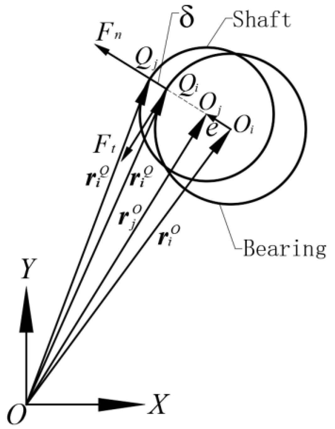
2.1. Revolute Joint Model with Clearance

The shaft and bearing of the revolute joint are viewed as independent parts, and Figure 1 depicts their model [14]. Where i ,     j stand for the bearing and shaft, O i ,     O j for the center of mass, Q i ,     Q j for the collision point at impact, r i O ,     r j O for the center of mass’ position vector, r i Q ,     r j Q for the position vector of collision point, and F n ,     F t for the normal contact force and tangential friction force at impact.
The eccentric vector between the bearing and shaft can be defined as follows:
e = r j O r i O
Its unit normal vector can be expressed as follows:
n = e / e
where e is the amplitude of the eccentric vector, e = e T e .
The angle between the eccentric vector and the positive direction of the X-axis can be defined as follows:
φ = cos 1 ( n · Ι )
where Ι is the unit vector in the positive direction of the X-axis.
The position vector of the collision point can be defined as follows:
r k Q = r k O + R k n         ( k = i , j )
where r i ,     r j are the radius of the bearing and shaft, respectively.
The velocity vector at the collision point is produced by taking the derivative of Equation (4) with respect to time, which can be stated as follows:
r ˙ k Q = r ˙ k O + R k n ˙         ( k = i , j )
The velocity vector at the collision point is projected onto the collision plane in the normal and tangential directions, then the relative normal and tangential velocities can be defined as the following:
{ v n = ( r ˙ i Q r ˙ j Q ) T n v t = ( r ˙ i Q r ˙ j Q ) T t
where t is the tangential vector, obtained by n rotating 90° counterclockwise.
The embedding depth between the bearing and shaft can be expressed as follows:
δ = e c
where c is clearance size, c = R i R j .

2.2. Contact Force Model

In the impact process, the normal contact force will cause certain shock and vibration, which greatly affects the performance of the mechanism, so the selection of the normal contact force model is an important step in the dynamic modeling process. In this study, the L-N contact force model [15] will be used, which is based on the spring damping model with the addition of energy dissipation, material properties, elastic deformation, and collision velocity to more closely match the actual situation, and it can be expressed as follows:
F n = K δ m ( 1 + 3 ( 1 c e 2 ) 4 δ ˙ δ ˙ ( ) )
where K is the stiffness coefficient, which can be defined as the following:
K = 4 3 ( h i + h j ) R i R j R i R j
where h k is combined constant, which can be defined as the following:
h k = 1 ν k 2 E k ( k = i , j )
where m is the power exponent of the metallic surface, c e is material recovery coefficient, δ ˙ ( ) is normal relative initial impact velocity, ν k is Poisson’s ratio, and E k is Elastic modulus.

2.3. Friction Force Model

In order to create dynamic friction, Ambrósio added the dynamic correction factor c d to the Coulomb friction model [16]. The model is capable of effectively describing the dry friction behavior between colliding entities as well as the viscous and micro-slip phenomenon that occur at very low velocities, while preventing numerical operations from becoming unstable owing to abrupt changes in the tangential velocity direction, hence increasing the stability of the numerical integration. It can be expressed as follows:
F t = c f c d F n ν t | ν t |
where c d is the dynamic correction factor, which can be defined as the following:
c d = { 0 | ν t | < v 0 | ν t | v 0 v 1 v 0 v 0 | ν t | v 1 1 | ν t | > v 1
where c f is coefficient of sliding friction, ν t is relative sliding velocity, v 0 , v 1 are the static and dynamic friction speed limits, respectively.

3. Dynamic Modeling

Figure 2 depicts the working mechanism of the jaw crusher with clearance in the revolute joint, which includes frame 0, eccentric shaft 1, moveable jaw 2, and elbow plate 3. The driving part is the eccentric shaft 1, which provides power to the moveable jaw 2 via the revolute joint A to accomplish the crushing operation. The components are all hard and difficult to bend, so the influence of revolute joint A on the mechanism is greater and the existence of its clearance must be taken into account [17], which has been represented in Figure 2a in an exaggerated manner.
The system generalized coordinates are q = [ x 1 , y 1 , θ 1 , x 2 , y 2 , θ 2 , x 3 , y 3 , θ 3 ] T . Ideally, eight constraint equations can be introduced for the four moving subsets; however, the existence of the clearance causes the constraint to fail at revolute joint A. The constraint equation can be shown as follows:
Φ ( q , t ) = [ x 1 l 0 sin θ 0 l 11 cos θ 11 y 1 l 0 cos θ 0 l 11 sin θ 11 x 2 l 3 cos θ 3 + l 2 sin θ 2 l 21 sin θ 21 y 2 + l 3 sin θ 3 l 2 cos θ 2 + l 21 cos θ 21 x 3 ( l 3 / 2 ) cos θ 3 y 3 + ( l 3 / 2 ) sin θ 3 ] = 0
where x 1 , y 1 , x 2 , y 2 , x 3 , y 3 represent the horizontal and vertical coordinates of the centers of mass S 1 , S 2 , S 3 , respectively. θ 0 , θ 1 , θ 2 , θ 3 represent the angle between each linkage and the coordinate axis, respectively. l 0 , l 1 , l 2 , l 3 represent the length of each linkage, respectively. l 11 , l 21 represent the length of the center of mass S 1 , S 2 to their left endpoints, respectively. θ 11 , θ 21 represent the angle between the line of the center of mass and the left endpoint and the coordinate axis, respectively, θ 11 = θ 1 + 30 ° , θ 21 = θ 2 + 15 ° .
By taking the first-order derivative of Equation (13) with respect to time, the velocity constraint equation is stated as follows:
Φ q q ˙ = Φ t v
where Φ q is the Jacobian matrix of the constraint equation. Φ t is the first-order derivative of the constraint equation with respect to time.
By taking the second-order derivative of Equation (13) with respect to time, the acceleration constraint equation is stated as follows:
Φ q q ¨ = ( Φ q q ˙ ) q q ˙ 2 Φ q t q ˙ Φ t t γ
where Φ q t is the time partial derivative of the Jacobian matrix. Φ t t is the second-order partial derivative of the constraint equation with respect to time.
The dynamic equation based on the Lagrange multiplier method (LMD) [18] can be defined as the following:
M q ¨ + Φ q T λ = Q F
where M is the generalized quality matrix, which can be shown as follows:
M = d i a g [ m 1 , m 1 , J 1 , m 2 , m 2 , J 2 , m 3 , m 3 , J 3 ]
where Q is the system generalized external forces, which can be shown as follows:
Q = [ 0 , m 1 g , M 0 , F l o a d sin θ 2 , m 2 g F l o a d cos θ 2 , 0 , 0 , m 3 g , 0 ] T
where F is the collision force matrix, which can be shown as follows:
F = { [ F n cos φ + F t sin φ , F n sin φ + F t cos φ , 0 , F n cos φ F t sin φ , F n sin φ F t cos φ , 0 , 0 , 0 , 0 ] T             δ > 0                                                                                           0                                                                                                 δ 0
where λ is the Lagrange multiplier array. m 1 , m 2 , m 3 are the masses of the eccentric shaft, moveable jaw, and elbow plate, respectively; J 1 , J 2 , J 3 are the rotational inertia, respectively; M 0 is the driving torque; F l o a d is the fixed load.
The displacement constraint equation and the velocity constraint equation are inserted into the system dynamic equation through Baumgarte’s default stabilization procedure [19], and the dynamic equation of the mechanism with clearance in the revolute joint is derived as follows:
( M Φ q T Φ q 0 ) ( q ¨ λ ) = ( Q F γ 2 α Φ ˙ β 2 Φ )
where α , β are Baumgarte stability factors, respectively.

4. Validation Analysis

The structural parameters of the working mechanism of the jaw crusher are shown in Table 1. The dynamic simulation parameters are shown in Table 2.
As can be observed from Equation (20), the dynamic equation is coupled and extremely nonlinear, hence it cannot be solved directly to produce a stable solution. Therefore, in this study, the equation is iteratively solved by the variable step fourth-order Runge–Kutta method [20] to minimize calculation error. The initial condition is set to the ideal state, and eccentric shaft 1 is parallel to the X-axis. The solution process is shown in Figure 3.

4.1. Validation of Dynamical Model

The primary components of the PE250 × 400 crusher are imported into Adams software for virtual prototype simulation in order to confirm the correctness of the dynamic model of the working mechanism of the crusher with clearance. The simulation interface is shown in Figure 4, and the results obtained are compared with those of MATLAB. The simulation parameters are the same in MATLAB and Adams, where the clearance size at the revolute joint A is 0.06 mm and the system driving speed is 30 rad/s.
After the mechanism has stabilized in operation, the displacement and velocity curves of the moveable jaw are shown in Figure 5a,b, respectively, and the collision force curve at the revolute joint A is shown in Figure 5c,d. Analysis of Figure 5a shows that the displacement curves obtained by Adams and those obtained by MATLAB are basically the same. A closer look at Figure 5b reveals that during motion, the velocity curve will exhibit noticeable fluctuations at the crest and trough. The fluctuation value of MATLAB is slightly larger, and the two curves essentially continue to overlap after the fluctuation. Analysis of Figure 5c,d shows that the collision forces at the revolute joint A obtained by Adams and MATLAB maintains the same waveform trend overall, although they exhibit complex nonlinear oscillations. There are slight differences in the curve fluctuations and peak magnitudes. In the time interval [12, 12.4], 12.099 s for the first time to reach the peak collision force of 37,796 N for Adams and 12.106 s for the first time to reach the peak collision force of 37,578 N for MATLAB.
In summary, the results from Adams and MATLAB are similar in terms of trends, which verifies the correctness of the dynamic model of the working mechanism of the crusher with clearance. The slight difference in the peak is analyzed for possible reasons [21]:
(1)
Errors in the structural parameters of the virtual prototype. Adams is deficient in modeling capability, so a 3D model of the crusher is built in SOLIDWORKS and imported into Adams, while some structural simplifications are made to the model, such as merging the bearing rollers of the eccentric shaft and thickening the revolute joint where the elbow plate is connected to the moveable jaw, resulting in minor changes in mass, volume and other parameters.
(2)
The difference between the two solution methods. The normal contact force model and the tangential friction force model in the dynamic model are not fully consistent with the mechanical model in Adams. In Adams, the collision forces between the components are defined using the Contact tool. The normal contact force is calculated by the Impact function in the function library, and the tangential friction force is calculated by the Coulomb friction model.

4.2. Validation of Influence Parameters

Crusher production capacity is defined as the volume of material that a crusher can crush per unit of time, which is an important indicator of crusher performance [22]. According to the lamination crushing theory (LCT), the movable jaw follows the eccentric shaft to move reciprocally once, and the ore will be crushed and moved down layer by layer until they are discharged from the crushing chamber. The specific discharge volume per unit of time is obtained by calculating the discharge volume of a single layer. The cross-section diagram of the broken layer is shown in Figure 6. B and b are the inlet size and discharge size when the movable jaw moves to the loose edge position, a is the engagement angle of the crushing chamber, H is the height of the crushing chamber, s is the horizontal travel of the lower end point of the movable jaw, AA1BB1 is the trapezoidal cross-section of the discharge prism during one movement cycle, and h is the height of the cross-section.
The crusher production capacity can be expressed as follows:
Q = 60 n V μ  
where V is the volume of material discharged once by the reciprocating motion of the moveable jaw, which can be defined as the following:
V = S · L  
where S is the area of the trapezoidal section of the prism, which can be defined as follows:
S = 2 b s 2 h  
when the material breaks away from the moveable jaw, it does free fall motion, so the height of the cross-section can be shown as follows:
h = 1 2 g t 2
In a motion cycle, the discharge time occupies half of the time, so the discharge time can be expressed as follows:
t = 30 n
where n is the eccentric shaft speed, g is the acceleration of gravity, L is the feed opening length, and μ is the loosening factor of the mineral.
Combined with the above equations, it can be seen that the production capacity of the crusher is determined by the eccentric shaft speed, the horizontal travel of the lower end point of the movable jaw and the discharge size. While the driving speed and the clearance size are important influencing factors of the shock and chaos phenomenon in the mechanism [23], if these two parameters are analyzed, their influence on the production capacity also needs to be considered. The driving speed corresponds to the eccentric shaft speed, and the clearance size corresponds to the horizontal travel of the lower end point of the movable jaw and the discharge size, i.e.,
Given a driving speed of 30 rad/s and common fit tolerances of 0.06 and 0.12 mm for the revolute joint A, a comparison of the displacement of the revolute joint B under different clearance size conditions is shown in Figure 7a. It can be seen that the displacement curves basically overlap, indicating that the change in clearance size will not affect the horizontal travel of the lower end point of the movable jaw and the discharge size, which will not affect the production capacity.
Taking granite ore crushing as an example, the given feed opening length is 0.4 m, the crushing chamber height is 0.6 m and the loosening factor is 0.7. According to Equation (21), the relationship between driving speed and production capacity of a PE250 × 400 compound pendulum jaw crusher can be obtained, as shown in Figure 7b. As can be seen from the figure, the production capacity decreases as the driving speed increases. The single-layer material fall height h should be less than the crushing chamber height H. Combining with Equations (24) and (25), the driving speed should be greater than 25 rad/s. Meanwhile, the maximum production capacity of the crusher is calculated as 9.41 m3/h. According to the definition of crusher production capacity affluence factor [24], the actual production capacity multiplied by the affluence factor over the maximum production capacity can meet the production demand and the general affluence factor k = 1.67. Therefore, the minimum production capacity allowed for the crusher is 5.63 m3/h, which corresponds to a maximum driving speed of 41.45 rad/s. For the convenience of the subsequent parameter analysis, the maximum driving speed is chosen to be 40 rad/s.
In summary, the influence of driving speed and clearance size on the working mechanism of the crusher should be studied without affecting production capacity. The range of driving speed and clearance size can be chosen as [25, 40] and [0.03, 0.12], respectively.

5. Analysis of Dynamic Performance

5.1. Influence of Driving Speed

Given the clearance size of 0.06 mm and the driving speed of 25, 30, 35, and 40 rad/s, Figure 8, Figure 9 and Figure 10 represent the characteristic images of the axial trajectory of the shaft, the vibration force applied to the foundation, and the Poincare mapping at different driving speeds, respectively.
In Figure 8, the solid circle, which has the origin as its center and the clearance size as its radius, stands for the axial motion boundary of the shaft. The distribution of the collision locations is formed by the contact between the motion trajectory and the solid circle. According to an analysis of Figure 8, the collision points are concentrated in the upper right corner of the boundary at 25 rad/s, chaotically distributed at 30 rad/s and 35 rad/s, and steadily embedded at 40 rad/s. It shows that as the driving speed increases, the shock phenomenon in the mechanism first increases and then decreases. The reason is that when the eccentric shaft is rotating at low speed, the moveable jaw is affected by gravity and fixed load, and the collision occurs mostly on the upper right side of the bearing and shaft, which is easy to cause irregular wear of the revolute joint. As the driving speed increases, the collision forces increase accordingly and the motion becomes chaotic. If the driving speed is further increased, it is difficult for the bearing to make a large movement in a very short period due to the inertia force, and it can only make a stable movement along the axis motion boundary.
According to an analysis of Figure 9, compared to the case when there is no clearance, the existence of clearance causes nonlinear oscillations in the vibration forces applied to the foundation. The peak vibration forces at 25 rad/s, 30 rad/s, 35 rad/s and 40 rad/s are 2.3 × 10⁴ N, 7.4 × 10⁴ N, 4.1 × 10⁴ N and 4 × 10⁴ N, which are consistent with the variation in the shock phenomenon. The amplitude of the oscillation is greatest at a driving speed of 30 rad/s, with a peak increase of approximately 180%. It shows that as the driving speed increases, the influence on the vibration force applied to the foundation and the foundation service life first increases and then decreases.
The Poincare mapping technique [25] is a qualitative approach to identifying the chaos phenomenon. When the discrete points show one or fewer, closed curves, hierarchical and banded distributions, it means that the system is in a state of periodic, quasi-periodic, and chaotic motion. Figure 10 shows that the Poincare mapping points display a band distribution and no association between neighboring mapping points as the driving speed increases, but the distribution range widens. At the driving speed of 40 rad/s, the distribution range of the Poincare mapping points shrinks and moves in the direction of a point-like trend. It shows that as the driving speed increases, the chaos phenomenon decreases and the stability of the mechanism increases. It is shown that as the driving speed increases, the chaos phenomenon, like the shock phenomenon, first increases and then decreases, i.e., the operating stability of the mechanism first decreases and then increases.
In summary, for a clearance size of 0.06 mm and a driving speed range of 25 rad/s to 40 rad/s, the driving speed of 40 rad/s is chosen as the best considering the wear problem. Therefore, in the case of a specific clearance size, the maximum value within the driving speed selection range should be selected, which can weaken the chaos and shock phenomenon in the mechanism, enhance the stability of the mechanism operation, weaken the influence of the clearance on the vibration force applied to the foundation, and prolong the service life of the foundation.

5.2. Influence of Clearance Size

Given the driving speed of 30 rad/s and the clearance size of 0.03, 0.06, 0.09, 0.12 mm, Figure 11, Figure 12 and Figure 13 represent the characteristic images of the axial trajectory of the shaft, the vibration force applied to the foundation, and the Poincare mapping at different driving speeds, respectively.
Analysis of Figure 11 shows that when the clearance size is 0.03 mm or 0.06 mm, the collision point distribution is chaotic. After increasing to 0.09 mm, the axial trajectory is distributed in an elliptical band, and the clearance joint elements contact stably. After increasing to 0.12 mm, the state remains stable and the embedding depth increases. It visually demonstrates the change process of the shock phenomenon that first enhances and then disappears as the clearance size increases. This is because the limited clearance sizes reduce the eccentric shaft’s range of motion and increase the likelihood of collisions. As the clearance size increases, the collision forces increase accordingly and the motion becomes chaotic. When the clearance size is increased to a certain level, the movable jaw is able to maintain contact with the eccentric shaft due to the inertial force and make a stable motion. This is consistent with the scenario of the “momentum exchange method” and the “massless linkage method” proposed by Flores [26].
Analysis of Figure 12 shows that the vibration force on the foundation is influenced by changes in the shock phenomenon and exhibits the same dynamic characteristics. When the clearance size is 0.03 mm and 0.06 mm, the peak vibration force is 6 × 10⁴ N and 7.4 × 10⁴ N, respectively, when the clearance size increases to 0.09 mm and 0.12mm, the change curve smooths out and the peak vibration force is 1.1 × 10⁶ N and 1.7 × 10⁶ N, respectively. However, at 0.12 mm, the mean vibration force with clearance is 8 × 10⁵ N and the mean vibration force without clearance is 1.8 × 10⁴ N, showing an increase of nearly 45 times in comparison, far exceeding the amplitude of oscillation at 0.06 mm. It is shown that the smaller the clearance size, the less the influence on the vibration force on the foundation and the less the influence on the service life of the foundation.
Analysis of Figure 13 shows that for the clearance size of 0.03 mm, there is no correlation between adjacent Poincare mapping points. After increasing to 0.06 mm, the distribution of mapping points expands. After increasing to 0.09 mm and 0.12 mm, the mapping points form a closed curve. It is shown that as the clearance size increases, the chaotic motion of the system gradually strengthens and then enters the state of quasi-periodic motion, where the stability of the mechanism operation first weakens and then strengthens.
In summary, for a driving speed of 30 rad/s and a clearance size range of 0.03 mm to 0.12 mm, the clearance size of 0.03 mm is chosen as the best considering the magnitude of the vibration force. Therefore, in the case of a specific driving speed, the minimum value within the clearance size selection range should be selected, which can weaken the chaos and shock phenomenon in the mechanism, enhance the stability of the mechanism operation, weaken the influence of the clearance on the vibration force applied to the foundation, and prolong the service life of the foundation.

5.3. Influence of Driving Speed and Clearance Size

Figure 14a shows the root-mean-square values of the vibration force on the foundation for a driving speed range of [25, 40] and a clearance size range of [0.03, 0.12]. The three-dimensional surface is able to show the magnitude of F r m s corresponding to different ( r , ω ) . The contour plots of F r m s are shown in Figure 14b, which can graphically express the effects of the driving speed and the clearance size together on the vibration force applied to the foundation.
Analysis of Figure 14a,b shows that the contours are densely distributed on the right side, and the value of each contour increases tenfold, from 1 × 10⁴ N all the way to 9 × 10⁴ N. It indicates that the vibration force increases sharply after the clearance size increases to a certain degree, which verifies the analysis of the vibration force in Section 5.2. The combination of driving speed and clearance size should be chosen from the darkest color part since its vibration force is much lower than that of the other parts and its influence on the service life of the foundation is likewise much smaller.
According to the previous analysis, the peak is able to reflect the shock phenomenon and the operational stability of the mechanism. Based on the conclusion in Section 5.2 on the selection of clearance size, the local surface and contour maps of the peak vibration force are plotted based on the darkest color part in Figure 14b with r = 0.06 mm as the dividing line. Figure 15a shows the peak vibration forces on the foundation for a driving speed range of [25, 40] and a clearance size range of [0.03, 0.06]. The three-dimensional surface is able to show the magnitude of F m a x corresponding to different ( r , ω ) . The contour plots of F m a x are shown in Figure 15b.
Analysis of Figure 15a,b shows that the contour distribution is complex, increasing from 2 × 10⁴ N all the way to 2 × 10⁵ N, where the darkest color part is distributed near the driving speed of 25 rad/s. Considering that a smaller driving speed can lead to irregular wear of the revolute joint, the combination solution is chosen from the part with the second darkest color. Combining the conclusions on the driving speed and clearance size selection in Section 5.1 and Section 5.2, the optimal combination solution is 39 rad/s and 0.03 mm, with a mean vibration force of 2.19 × 10⁴ N and a peak vibration force of 3.8 × 10⁴ N.
Bo, etc., [27] analyzed the effect of the revolute joint with clearance on the dynamic characteristics of the PE250 × 400 compound pendulum jaw crusher in terms of jaw speed, acceleration and vibration force at a driving speed of 30 rad/s and a clearance size of 0.06 mm. Some of the characteristic images are shown in Figure 8b, Figure 9b and Figure 10b. Figure 16 shows the axis trajectory of the shaft, the vibration force applied to the foundation, and the Poincare mapping of the crusher with clearance when the optimal driving speed and clearance size suggested in this study are utilized.
Comparing Figure 8b with Figure 16a, Figure 9b with Figure 16b, and Figure 10b with Figure 16c, it is clear that the optimal combination solution significantly reduces the shock and chaos phenomenon in the mechanism, maintains the stable contact between the revolute joint’s elements, and reduces the peak vibration force applied to the foundation from 7.4 × 10⁴ N to 3.8 × 10⁴ N, or about 48.6%, with a smooth change curve.

6. Conclusions

Dynamics analysis and chaos identification of the compound pendulum jaw crusher with joint clearance is conducted in this paper. Because the existing research only focuses on the optimal design of the crusher structure and the existence of clearance is neglected, this study introduces chaos into the dynamic characteristic evaluation system and analyses the effect of clearance on the crusher under different driving speeds and clearance sizes. On the basis of the proposed theoretical investigations, the obtained major conclusions can be drawn:
  • Comparative simulations in MATLAB and Adams verify the correctness of the clearance mechanism modeling method and solution method, which provides a reference for the research on the dynamics of crushers with clearance.
  • The dynamic simulation analysis verifies that the existence of clearance leads to significant oscillations in the vibration forces, which seriously affect the service life of the foundations. A larger driving speed and a smaller clearance size can be beneficial to reduce the shock and chaos phenomenon during the operation of the mechanism, reduce the influence of the clearance on the vibration force applied to the foundation, and improve the stability of the mechanism operation.
  • Analysis of the combined effect of driving speed and clearance size shows that the optimal combination of 39 rad/s and 0.03 mm reduces the peak vibration force by 48.6% while meeting the crusher production capacity.

Author Contributions

Conceptualization, Y.C. and S.W.; methodology, S.W.; software, S.W.; validation, Y.C., S.W. and C.W.; formal analysis, S.W.; investigation, S.W.; resources, Y.C.; data curation, S.W.; writing—original draft preparation, S.W.; writing—review and editing, S.W.; visualization, Y.C.; supervision, C.W.; project administration, C.W.; funding acquisition, Y.C. All authors have read and agreed to the published version of the manuscript.

Funding

This research was funded by National Natural Science Foundation of China (12272217).

Institutional Review Board Statement

Not applicable.

Informed Consent Statement

Not applicable.

Data Availability Statement

The data are available from the corresponding author upon reasonable request.

Conflicts of Interest

The authors declare no conflict of interest.

References

  1. Barrios, G.K.; Jiménez-Herrera, N.; Fuentes-Torres, S.N.; Tavares, L.M. DEM Simulation of Laboratory-Scale Jaw Crushing of a Gold-Bearing Ore Using a Particle Replacement Model. Minerals 2020, 10, 717. [Google Scholar] [CrossRef]
  2. Deniz, V. A Study on the Effects of Coal Feed Size and Coal Type on the Performance of a Laboratory Jaw Crusher. Energy Sources Part A 2014, 36, 1249–1255. [Google Scholar] [CrossRef]
  3. Ulsen, C.; Tseng, E.; Angulo, S.C.; Landmann, M.; Contessotto, R.; Balbo, J.T.; Kahn, H. Concrete Aggregates Properties Crushed by Jaw and Impact Secondary Crushing. J. Mater. Res. Technol. 2019, 8, 494–502. [Google Scholar] [CrossRef]
  4. Osanloo, M.; Paricheh, M. In-pit Crushing and Conveying Technology in Open-pit Mining Operations: A Literature Review and Research Agenda. Int. J. Min. Reclam. Environ. 2020, 34, 430–457. [Google Scholar] [CrossRef]
  5. Lapin, S.K. Vibration Insulation for Jaw Crushers—An Effective Means of Reducing Bed and Foundation Deformations. Soil Mech. Found. Eng. 2000, 37, 198–201. [Google Scholar] [CrossRef]
  6. Yang, C.L.; Huang, D.M.; Xiong, J.F.; Liu, X.H. The Weight Reduction Optimization of Jaw Crusher about Moving Jaw Based on Parametric Finite Element Analysis. In Proceedings of the 1st International Workshop on Hydraulic Equipment and Support Systems for Mining (IWHEM 2012), Huludao, China, 17–18 August 2012; p. 275. [Google Scholar]
  7. Li, Z.; Chen, W.; Zhang, W.; Zhang, X.; Wen, B. Theoretical, Numerical, and Experimental Study on the Synchronization in a Vibrator–pendulum Coupling System. Arch. Civ. Mech. Eng. 2022, 22, 157. [Google Scholar] [CrossRef]
  8. Cheng, J.; Ren, T.; Zhang, Z.; Jin, X.; Liu, D. Influence of Two Mass Variables on Inertia Cone Crusher Performance and Optimization of Dynamic Balance. Minerals 2021, 11, 163. [Google Scholar] [CrossRef]
  9. Zhao, Z.; Li, Y.; Li, W.; Zhan, X.; Zhu, X.; Zhong, J. Research on the Biaxial Compound Pendulum Jaw Crusher Based on Seven-bar Mechanism. Proc. Inst. Mech. Eng. Part C J. Mech. Eng. Sci. 2015, 230, 1876–1889. [Google Scholar]
  10. Wang, X.; Liu, G.; Ma, S. Dynamic Analysis of Planar Mechanical Systems with Clearance Joints Using a New Nonlinear Contact Force Model. J. Mech. Sci. Technol. 2016, 30, 1537–1545. [Google Scholar] [CrossRef]
  11. Chen, X.; Jiang, S.; Deng, Y.; Wang, Q. Dynamics analysis of 2-DOF complex planar mechanical system with joint clearance and flexible links. Nonlinear Dyn. 2018, 93, 1009–1034. [Google Scholar] [CrossRef]
  12. Wu, X.; Sun, Y.; Wang, Y.; Chen, Y. Correlation Dimension and Bifurcation Analysis for the Planar Slider-crank Mechanism with Multiple Clearance Joints. Multibody Syst. Dyn. 2021, 52, 95–116. [Google Scholar] [CrossRef]
  13. Chen, X.; Jia, Y.; Deng, Y.; Wang, Q. Dynamics Behavior Analysis of Parallel Mechanism with Joint Clearance and Flexible Links. Shock Vib. 2018, 2018, 9430267. [Google Scholar] [CrossRef]
  14. Farahan, S.B.; Ghazavi, M.R.; Rahmanian, S. Bifurcation in a Planar Four-bar Mechanism with Revolute Clearance Joint. Nonlinear Dyn. 2017, 87, 955–973. [Google Scholar] [CrossRef]
  15. Lankarani, H.M.; Nikravesh, P.E. A Contact Force Model With Hysteresis Damping for Impact Analysis of Multibody Systems. J. Mech. Des. 1990, 112, 369–376. [Google Scholar] [CrossRef]
  16. Ambrósio, J.A.C. Dynamics of Structures Undergoing Gross Motion and Nonlinear Deformations: A Multibody Approach. Comput. Struct. 1996, 59, 1001–1012. [Google Scholar] [CrossRef]
  17. Chen, X.; Wang, J. Nonlinear Dynamic Analysis and Experimental Study of Multi-link Press with Dry Friction Clearances of Revolute Joints. Meccanica 2022, 57, 2627–2652. [Google Scholar] [CrossRef]
  18. Chen, X.; Guo, J. Effects of Spherical Clearance Joint on Dynamics of Redundant Driving Spatial Parallel Mechanism. Robotica 2021, 39, 1064–1080. [Google Scholar] [CrossRef]
  19. Baumgarte, J. Stabilization of Constraints and Integrals of Motion in Dynamical Systems. Comput. Methods Appl. Mech. Eng. 1972, 1, 1–16. [Google Scholar] [CrossRef]
  20. Bai, Z.F.; Zhao, Y.; Chen, J. Dynamics Analysis of Planar Mechanical System Considering Revolute Clearance Joint Wear. Tribol. Int. 2013, 64, 85–95. [Google Scholar] [CrossRef]
  21. Chen, X.; Jiang, D. Design, Kinematics, and Statics of a Novel Wave Energy Converter with Parallel Mechanism. Int. J. Adv. Robot. Syst. 2019, 16, 1729881419876214. [Google Scholar] [CrossRef]
  22. Zhong, X.; Niu, X.; Ji, Q.; Shen, X. Simulation Analysis of Cavity Shape of Compound Pendulum Jaw Crusher. J. Phys. Conf. Ser. 2020, 1637, 012130. [Google Scholar] [CrossRef]
  23. Tang, Y.; Chang, Z.; Dong, X.; Hu, Y.; Yu, Z. Nonlinear Dynamics and Analysis of a Four-bar Linkage with Clearance. Front. Mech. Eng. 2013, 8, 160–168. [Google Scholar] [CrossRef]
  24. Chen, Z.; Wang, G.; Xue, D.; Bi, Q. Simulation and Optimization of Gyratory Crusher Performance Based on the Discrete Element Method. Powder Technol. 2020, 376, 93–103. [Google Scholar] [CrossRef]
  25. Javanfar, A.; Bamdad, M. Effect of Novel Continuous Friction Model on Nonlinear Dynamics of the Mechanisms with Clearance Joint. Proc. Inst. Mech. Eng. Part C J. Mech. Eng. Sci. 2021, 236, 6040–6052. [Google Scholar] [CrossRef]
  26. Flores, P.; Ambrosio, J. Revolute Joints with Clearance in Multibody Systems. Comput. Struct. 2004, 82, 1359–1369. [Google Scholar] [CrossRef] [Green Version]
  27. Bo, S.J.; Guo, R.B.; Zhu, H. Dynamic Study for Working Device of PE-250*400 Crusher. Adv. Mater. Res. 2013, 753–755, 1699–1702. [Google Scholar] [CrossRef]
Figure 1. Revolute joint model with clearance.
Applsci 13 00238 g001
Figure 2. Working mechanism of the jaw crusher with clearance. (a) Demonstration of mass, rotational inertia and load; (b) Demonstration of length and angle.
Applsci 13 00238 g002
Figure 3. Flow chart for solving dynamic equation.
Applsci 13 00238 g003
Figure 4. Adams virtual simulation interface.
Applsci 13 00238 g004
Figure 5. Comparison of results from Adams and MATLAB: (a) Moveable jaw displacement; (b) Moveable jaw velocity; (c,d) Collision force at the revolute joint A.
Applsci 13 00238 g005
Figure 6. Cross-section diagram of the broken layer.
Applsci 13 00238 g006
Figure 7. Actual results of influence parameters: (a) Displacement of revolute joint B at different clearance sizes; (b) Relationship between eccentric shaft speed and production capacity.
Applsci 13 00238 g007
Figure 8. Axis trajectory of shaft at different driving speeds. (a) ω = 25 . (b) ω = 30 . (c) ω = 35 . (d) ω = 40 .
Applsci 13 00238 g008
Figure 9. Vibration force on the foundation at different driving speeds. (a) ω = 25 . (b) ω = 30 . (c) ω = 35 . (d) ω = 40 .
Applsci 13 00238 g009
Figure 10. Poincare mapping at different driving speeds. (a) ω = 25 . (b) ω = 30 . (c) ω = 35 . (d) ω = 40 .
Applsci 13 00238 g010
Figure 11. Axis trajectory of shaft at different clearance sizes. (a) r = 0.03 . (b) r = 0.06 . (c) r = 0.09 . (d) r = 0.12 .
Applsci 13 00238 g011
Figure 12. Vibration force on the foundation at different clearance sizes. (a) r = 0.03 . (b) r = 0.06 . (c) r = 0.09 . (d) r = 0.12 .
Applsci 13 00238 g012
Figure 13. Poincare mapping at different clearance sizes. (a) r = 0.03 . (b) r = 0.06 . (c) r = 0.09 . (d) r = 0.12 .
Applsci 13 00238 g013
Figure 14. Root-mean-square values of the vibration force on the foundation: (a) r ω F r m s three-dimensional surface diagram; (b) r ω F r m s contour map.
Applsci 13 00238 g014
Figure 15. Peak vibration forces on the foundation: (a) r ω F m a x three-dimensional surface diagram; (b) r ω F m a x contour map.
Applsci 13 00238 g015
Figure 16. Optimized dynamic characteristic images: (a) the axis trajectory of shaft; (b) the vibration force applied to the foundation; (c) the Poincare mapping.
Applsci 13 00238 g016
Table 1. Structural parameters of the jaw crusher mechanism.
Components * Rotational   Inertia   J Quality   m Length   L
frame 025970.64
eccentric shaft 10.2950.01
moveable jaw 2128.485240.695
elbow plate 30.7154220.3
* The units of each parameter are kg·m2, kg, m, respectively.
Table 2. Dynamic simulation parameters.
ParameterNumerical ValueParameterNumerical Value
m 1.5 E k 207 Gpa
c e 0.9 v 0 0.1 m/s
v k 0.29 v 1 1 m/s
c f 0.1 F l o a d 8.8 KN
α 20 δ ˙ ( ) 0.5 m/s
β 20 θ 0 22.5°
R i 0.13 m θ 1
l 21 0.006 m l 21 0.3 m
Disclaimer/Publisher’s Note: The statements, opinions and data contained in all publications are solely those of the individual author(s) and contributor(s) and not of MDPI and/or the editor(s). MDPI and/or the editor(s) disclaim responsibility for any injury to people or property resulting from any ideas, methods, instructions or products referred to in the content.

