Article

Optimization of Locking Plate Screw Angle Used to Treat Two-Part Proximal Humerus Fractures to Maintain Fracture Stability

by
Angel D. Castro-Franco
1,
Ismael Mendoza-Muñoz
1,
Alvaro González-Angeles
1,*,
Mildrend I. Montoya-Reyes
1 and
Nun Pitalúa-Díaz
2
1
Facultad de Ingeniería, Universidad Autónoma de Baja California, Blvd. Benito Juárez S/N, Mexicali 21280, Baja California, Mexico
2
Departamento de Ingeniería Industrial, Universidad de Sonora, Blvd. Luis Encinas y Rosales S/N, Col. Centro, Hermosillo 83000, Sonora, Mexico
*
Author to whom correspondence should be addressed.
Appl. Sci. 2022, 12(9), 4739; https://doi.org/10.3390/app12094739
Submission received: 8 April 2022 / Revised: 5 May 2022 / Accepted: 6 May 2022 / Published: 8 May 2022

Abstract

:
Proximal humerus fractures increase with the aging of the population. Due to the high failure rates of surgical treatments such as open reduction and internal fixation (ORIF), biomechanical studies seek to optimize the treatments and intervening factors to improve the quality of life of people undergoing these treatments. The aim of the present study was to determine the optimal insertion angle configuration of screws used in a two-part proximal humerus fracture-locking plate osteosynthesis treatment based on finite element analysis (FEA). A series of 3D models of PHILOS locking plates with different screw insertion angle configurations were designed using a matrix system for screw angulation. The locking plate models were evaluated in a two-part proximal humerus fracture with surgical neck fracture under bending and compressive loading conditions using FEA and statistically analyzed using a design of experiments (DOE). The optimal screw insertion angle setting showed an improvement in relation to the interfragmentary strain value of the fracture. Moreover, calcar screws were the most significant feature in fracture stability throughout the tests, followed by the divergence of the most proximal screws and the proximal–distal alignment of the locking plate.

1. Introduction

Proximal humerus fractures are becoming more frequent in older adults [1], caused by the motor deficiencies and the poor bone quality that the natural aging process brings with it [2]. These fractures are difficult to treat due to the complex union of the shoulder and the variations that the fracture can present [3]. Due to the abovementioned factors, the choice of treatment is based on the characteristics of the patient and the fracture [4]. However, the surgical treatment that today presents the best results is osteosynthesis using a locking plate [5] despite the risks involved and the increase in its failure rate.
In search of treatment optimization, the scientific community directed its studies to the assessment of the factors considered significant to the stability of the fracture [6,7]. Thus, the relevance of the locking plate configuration and its effect on the bone-healing process of the fracture was discovered [8,9]. One of the most interesting parameters is the configuration of the screws used for locking plate fixation [4].
The general problem is the rise in the rate of premature failures that occur in locking plate osteosynthesis treatment for proximal humerus fractures that ends up directly affecting the quality of life of geriatric patients who receive the treatment [1].
The specific problem is the absence of an optimal configuration regarding the angle of insertion of the screws used in the osteosynthesis treatment using a locking plate that results in low stability of the fracture during treatment. Finding the optimal configuration considering mechanical and anatomical limitations of the human body supposes an increase in the stability of the fracture and its fixation that will result in the prevention of premature failures of the treatment and in the improvement of the quality of life of patients [10].
The scientific community has assessed the most significant parameters in relation to the configuration of the locking plate and its effect on the stability of the fixation system [11]. Being a complex and changing system due to singularities of both the patient (age, comorbidities, bone quality, sex, etc.) and fracture type (location of the fracture, presence of impaction, comminution, displacement, etc.), the knowledge necessary to strengthen the stability of the system has not been totally covered considering the existing research [3].
Among the most relevant studies carried out by researchers with the purpose of perfecting the treatment are: the assessment of the effect of material type with which the blocking plate was manufactured, the differences generated by the different types of screws, the importance of the use of calcar screws, the effect on system stability caused by the type of screw hole in the locking plate, improvement of the fatigue performance of high cycle materials by cryogenic treatment and the prediction of premature system failure by determining the optimal number of screws for treatment [5,7,12,13,14,15].
This research offers a new biomechanical approach to solve the problem. Determining the optimal screw insertion angle configuration used in the locking plate to treat two-part proximal humerus fractures [16], significant stability in fracture fixation will be achieved by obtaining the appropriate percentage of interfragmentary deformation of the fractured segments that benefits the natural process of bone consolidation of the fracture [17,18].

2. Materials and Methods

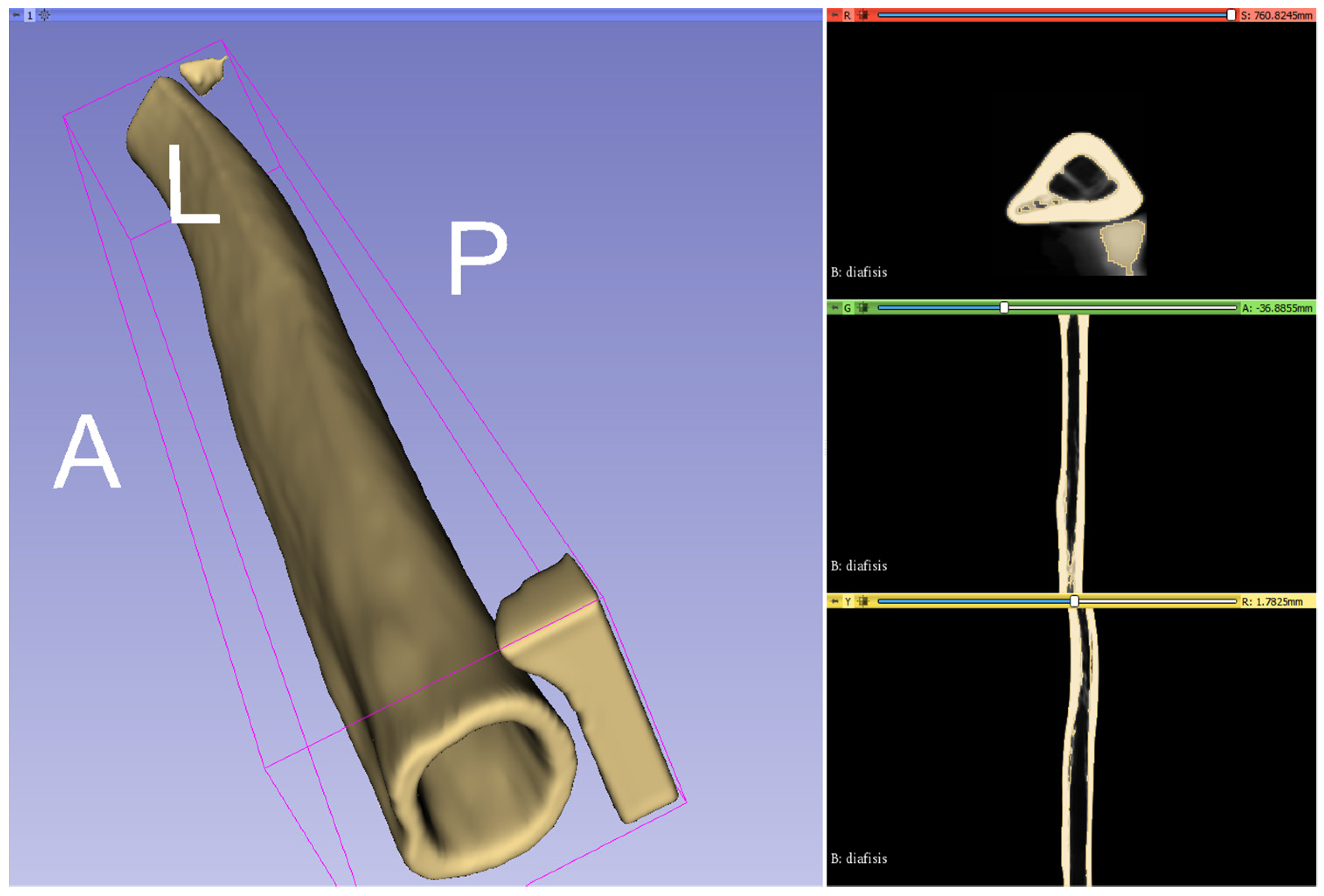
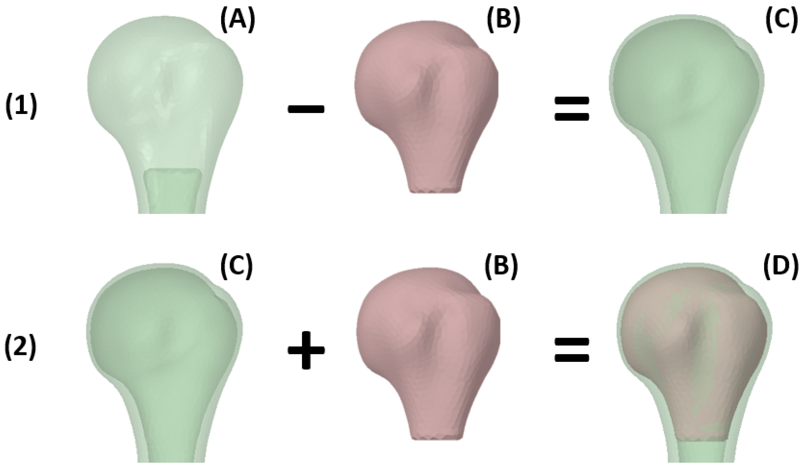
2.1. Proximal Humerus Modeling

Medical images of bone or biological tissue can be obtained by computed tomography (CT) or magnetic resonance imaging (MRI). These devices generate a set of images whose quantity and quality depend on the increments between each captured image and its resolution for each captured plane. The format used for this type of images is DICOM (digital imaging and communication in medicine), specially designed for the medical community because it contains captured patient images and both clinical and personal patient data. This avoids the incorrect assignment of images between different patients, and, in turn, standardizes the transmission of medical images.
The DICOM images used for the present investigation were obtained from the website of the International Society for Biomechanics [19]. Images of the humerus were collected via CT at the Human Anatomy and Embryology Laboratory at the University of Brussels, Belgium. The humerus is considered a long bone, so the images were captured in three sections (distal, diaphysis and proximal); therefore, the reconstruction and union of the sections of interest was necessary. For the segmentation, the threshold of Hounsfield units (HU) was defined. That would allow identifying only the cortical bone tissue of the structure. The threshold defined for the present investigation was from −170 to 2380 HU according to Zhao et al. [20] (Figure 1).
3D Slicer v4.11 software [21] was selected to perform the segmentation of the images used in the present investigation since it is not only free to use but has also been used in biomechanical investigations such as that carried out by Solorzano et al. [22].
The integration, reduction and model simplification were carried out by Autodesk Meshmixer v3.5 software [23]. First, the models were imported in STL format to the software. After using the Boolean union tool, both structures were merged. Seeking to soften the union previously made between both structures, 3D sculpture tools were used within the same software. The whole process allowed the model to be reduced by 90% without losing its original shape, from 269,074 total triangles to 35,182. Model subtraction and conversion of the surfaces to solids was performed in ANSYS SpaceClaim® 2020.R2 software. After importing the models, the meshing of the surfaces was homogenized using the Regularize tool, for which a maximum element size of 1 mm and a 60° angle threshold were defined. Finally, the subtraction of the models was continued using the Substract tool, mesh homogenization and conversion of the models to solids (Figure 2).

2.2. PHILOS Locking Plate Modeling

Three-dimensional modeling of the proximal humerus, PHILOS locking plate and system fixation elements was performed in SolidWorks® 2020 SP5.0 software [24]. The modeling was carried out from the superposition of images obtained from the manufacturer user manual of the PHILOS locking plate [25] and were supplemented by measurements provided in the Synthes Plates and Screws Catalog [26]. The final thickness was 2.5 mm with nine 2.9 mm holes (3.5 mm locking screw inner diameter specified by the manufacturer [26]) with angles obtained from the study by Hamandi et al. [27] (Figure 3).

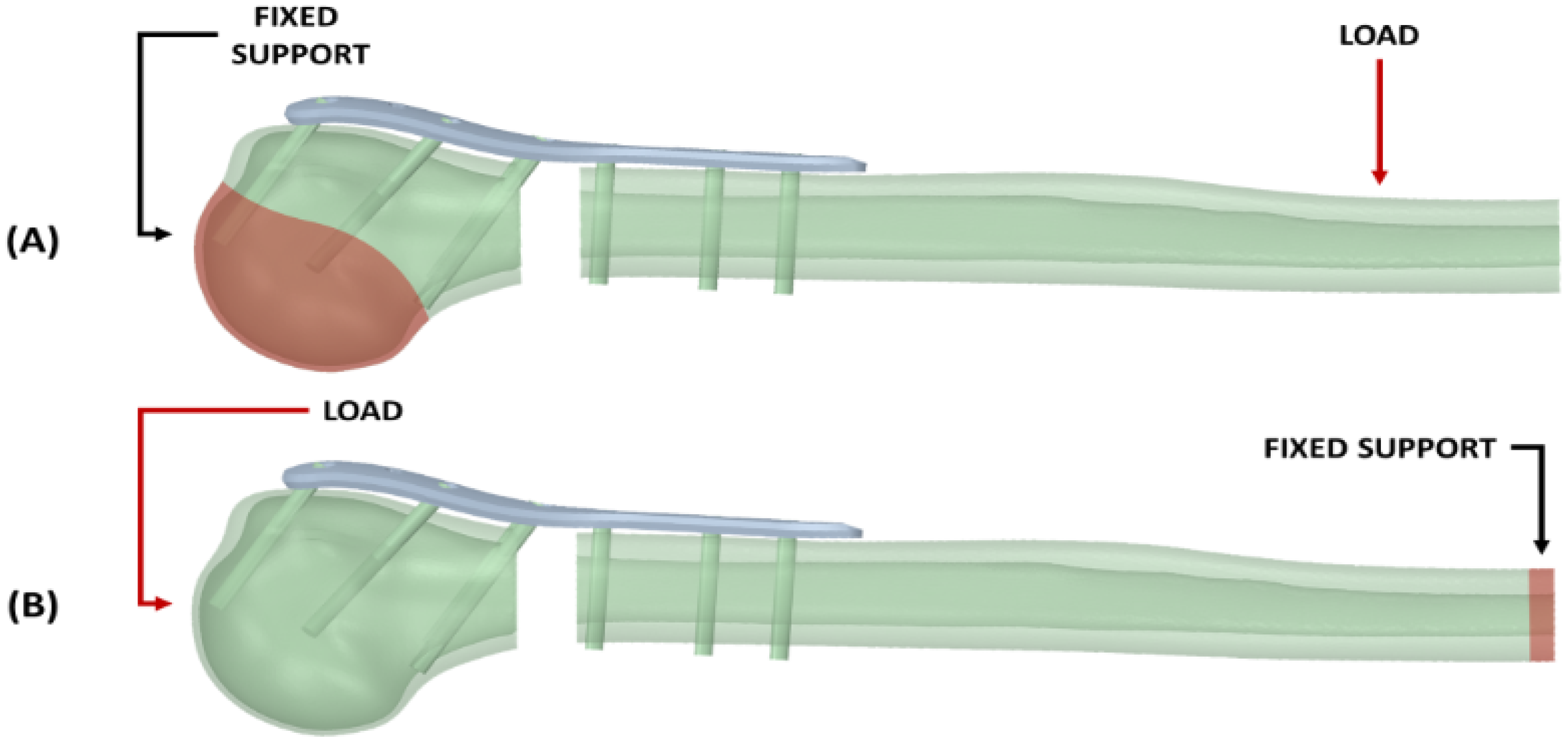
2.3. Considerations for Finite Element Analysis FEA

To perform the analysis for the locking plate along with the two-part fracture of the proximal humerus, the following considerations were put in place. The screw models were simplified to a simple isotropic cylinder with a diameter of 2.9 mm resembling the inside diameter of 3.5 mm locking screws. Bone tissues were considered isotropic, with a modulus of elasticity (E) of 15.6 GPa and 0.47 GPa for the cortical and cancellous bone, respectively. An average Poisson’s ratio (v) = 0.3 was taken from the literature [28]). In the experiment, 316L stainless steel (E = 190 GPa [18] and v = 0.3) was assigned as the material of manufacture for all fixation elements. The boundary conditions for screw-plate and bone-plate interactions were fixed, assuming ideal locking between the elements. The mesh of the bone and plate models was set tetrahedral and quadratic with a maximum element size of 1.5 mm and 1.0 mm for the bone tissues and the locking plate, respectively. The final meshing of all system models resulted in a total of 414,407 elements and 936,614 nodes. For the validation of our system elements, published models by Jabran et al. (flexion test) [29] and Zhang et al. (compression test) [13] were recreated (Figure 4).

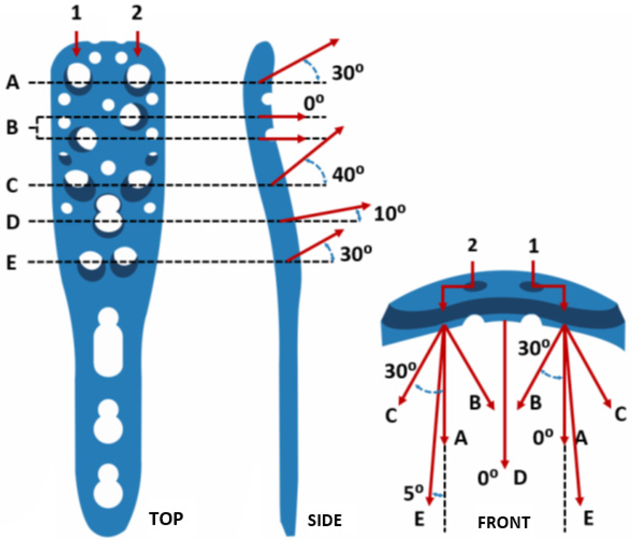
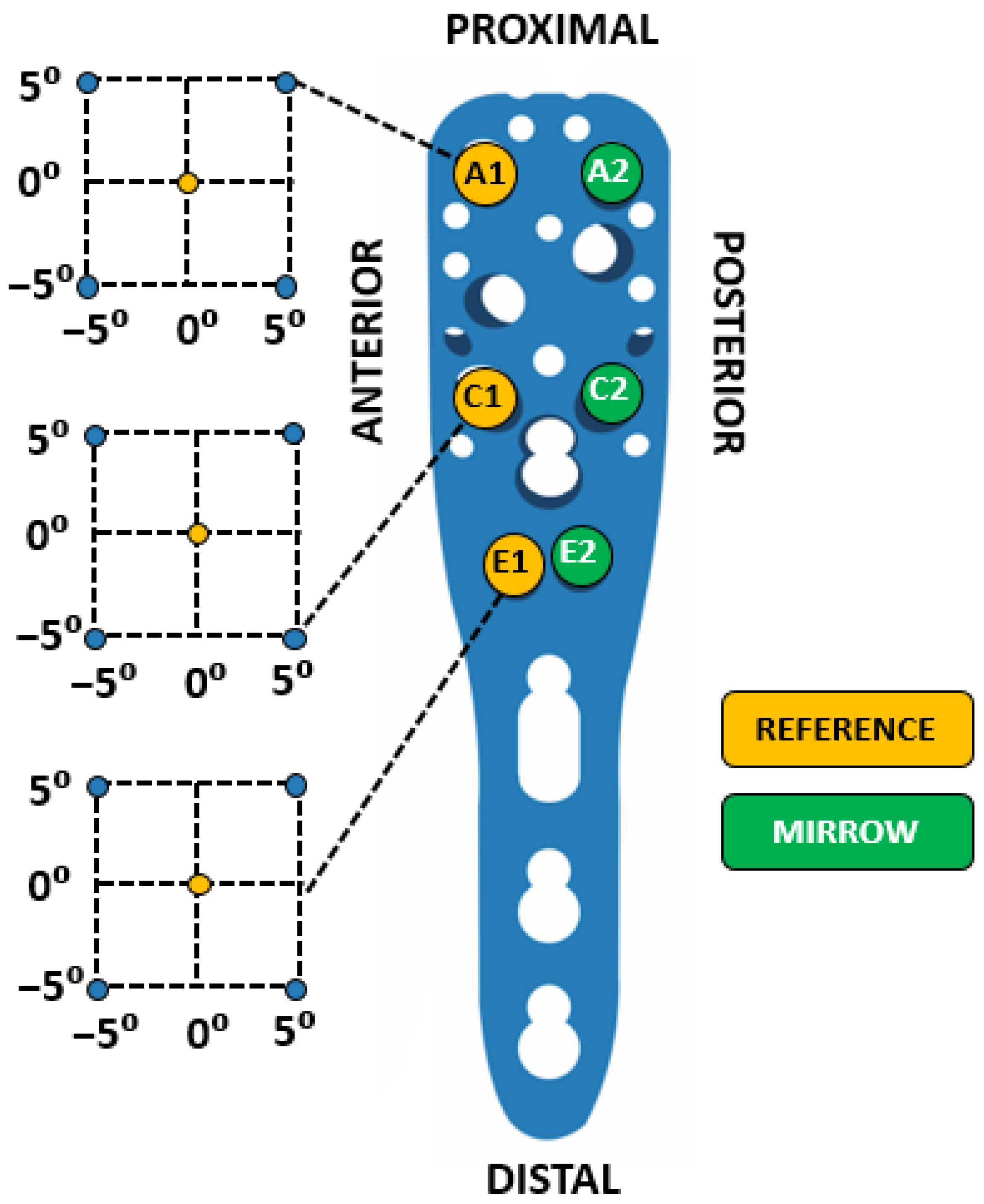
2.4. Screw Angle Direction

For the angulation of the locking plate screws, a design of experiments (DOE) was performed based on the matrix system proposed in the study by Flechler et al. [10], with the difference that for the present study the matrix system was adapted with only 5° of freedom for each screw. The screws were not evaluated individually but in pairs like a mirror as shown in Figure 5.

2.5. Design of Experiments

The response variable of the design of experiments would be the deformation (strain, ε) of the fracture spacing which was sought to ensure being within the optimal range (2–10%) suggested by the theory of interfragmentary deformation [30]. Thus, we sought to fix most of the non-controllable factors of the system to leave only those controllable and of interest for the study; therefore, the DOE factors were the angle of insertion of the screws broken down into two axes (X and Y) for each pair of screws. That is, the experiment would have six factors: Ax, Ay, Cx, Cy, Ex andEy. On the other hand, according to the matrix designed for the angulation of the screws, the DOE would have two levels for each factor, −5° and 5°.
Due to the number of experimental runs necessary to analyze all the combinations generated by the six factors of the DOE, it was decided to carry out a 26−2 fractional factorial design which corresponds to the representation of the fourth part of the complete design. The design used was resolution IV made up of 17 experimental runs and1 replica, including a central point.

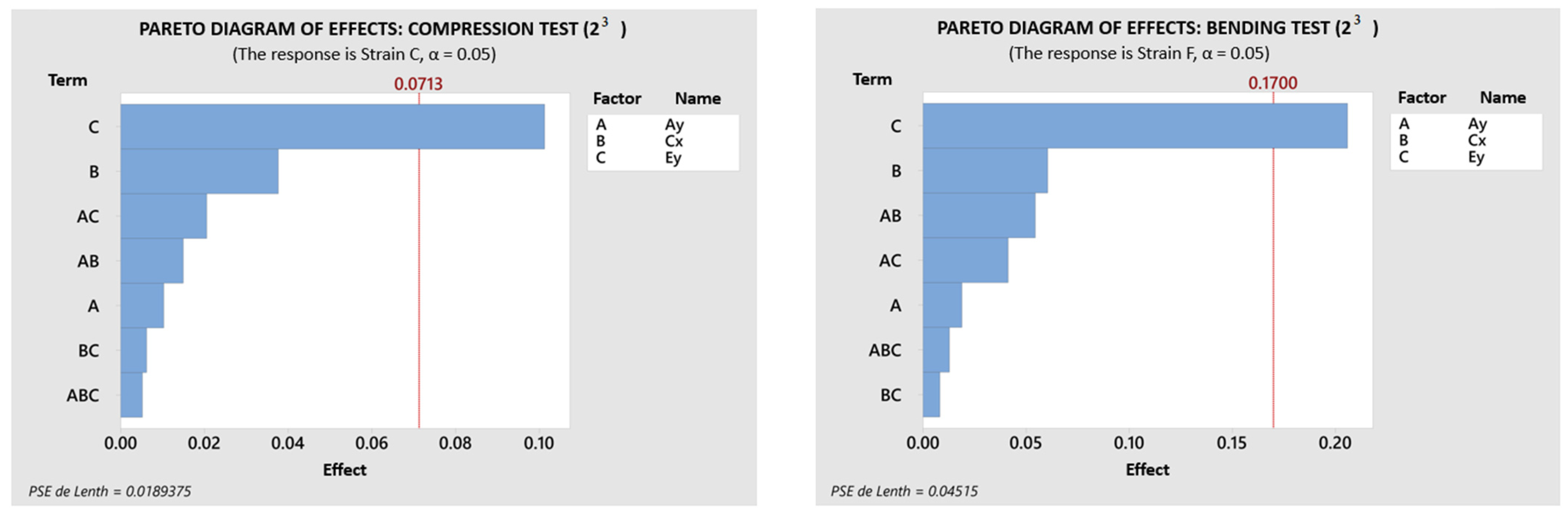
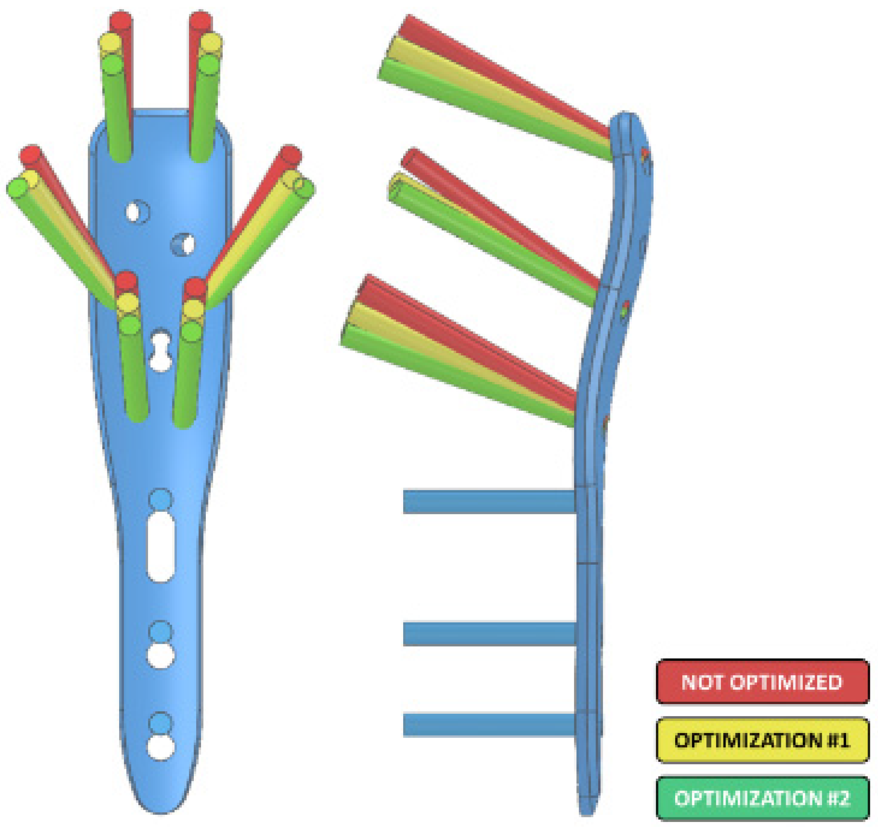
3. Results and Discussions

Experimentation and Statistical Analysis

It was decided to use the boundary conditions and configuration parameters applied in the validation of the system through the bending and compression tests with the difference that 17 experimental runs would be carried out for each test mode, each with a different configuration with respect to the angle of the bolts based on DOE 26−2. To homogenize the results, 316L stainless steel was assigned as the manufacturing material for the fixing elements. Each run implied a different design of the PHILOS plate, so the 17 models of the blocking plates were modeled in SolidWorks® program, and later, the assemblies and meshes were readapted to the new conditions of each particular configuration. The lengths of the screws were also adjusted according to each assembly, always seeking to use the longest screws for each hole, avoiding their penetration through the bone; the lengths used were 25, 30 and 35 mm.
After carrying out the 34 experimental runs (17 for each test) using the maximum displacement values of the two-part fracture, the interfragmentary deformation was calculated. To calculate the interfragmentary deformation of each test, the maximum displacement of the fracture was taken as reference, divided by the original fracture gap and converted to a percentage by multiplying the value obtained by 100.
The experimental runs achieved a coefficient of determination (R2) of 97.46% and 96.37% for the bending and compression tests, respectively, while the assumptions of the statistical model (normality, constant variance and independence) were fulfilled. Both tests exhibited similar significance patterns: Ey (p = 0.000), Cx (p = 0.001) and Cy (p = 0.001) for flexion and Ay (p = 0.000), Ey (p = 0.000) and Cx (p = 0.002) for compression.
According to the results of the experimentation, it was determined that the configuration of the insertion angles that would present the least interfragmentary deformation in both loading conditions was Ax: −5°, Ay: −5°, Cx: −5°, Cy: −5°, Ex: 0° and Ey: −5°. The suggested optimum level for the factor was used as the new central reference point in the matrix system for the angle of insertion. Additionally, a new design of experiments was created considering only the axis of greatest significance for each screw pair, according to the previously obtained results: Ay, Cx and Ey. Due to the reduction of the DOE factors, it was possible to carry out a complete design, specifically a 23 factorial design, composed of eight experimental runs and a central point. The new DOE required nine new models of the PHILOS plate. Finally, the same procedures were carried out as for the design of the previous 17 plates.
Once all 18 experimental tests were completed, 95.73% and 96.84% of R2 were obtained for the bending and compression tests, respectively. In both loading modes, the significance of Ey was imminent, p = 0.001 in bending and compression, with Cx and Ay ceasing to be significant factors. The Pareto diagram of effects for tests exhibited these results as shown on Figure 6. Therefore, the new configuration that presented the least interfragmentary deformation based on the new reference points was: Ay: −5°, Cx: −5° and Ey: −5°. Thus, the global optimum configuration up to this point would be Ax: −5°, Ay: −10°, Cx: −10°, Cy: −5°, Ex: −0° and Ey: −10°.
Finally, a new series of experimental runs was carried out based on the new optimal configuration, considering only the Ey factor given its statistical significance. The new experimentation would have three experimental runs only, the known levels −5° and 5° and the central point. The values of interfragmentary deformation (ε) collected coincided again in the configuration with a lower percentage of deformation than DOE 23. In other words, the model reached its maximum optimization point. The graphical comparison of the original configuration and the successive optimizations of the angles can be seen in Figure 7. In addition, Table 1 shows the numerical comparison between the worst screw angles configuration and the best one based on the last optimization in both bending and compression tests using interfragmentary strain (ε) as numerical reference.

4. Conclusions

The optimal screw insertion angle setting was determined. This configuration exhibited a percentage improvement related to the value of the interfragmentary strain of the fracture, ensuring the fracture stability and bone consolidation. Furthermore, the importance of calcar screws on fracture stability was evident as they were the most significant effect throughout the tests (E1–E2 screws). In addition, the divergence of the proximal screws was highlighted as it provides better support for various loading conditions. However, the optimal configuration discovered is limited to the characteristics of the present study since the screw angles were studied in isolation from the other factors involved in achieving fracture stability. Thus, even when the objective of the study was achieved, the results cannot be definitive. To be so, it is necessary to perform a series of validations through physical tests, consider proximal distal locking plate position as a factor and test the optimal configuration in the different variations of the proximal humerus fracture.

Author Contributions

Conceptualization, A.D.C.-F., I.M.-M. and A.G.-A.; methodology, M.I.M.-R.; investigation, A.D.C.-F. and I.M.-M.; writing—original draft preparation, A.D.C.-F. and N.P.-D.; writing—review and editing, I.M.-M. and A.G.-A. All authors have read and agreed to the published version of the manuscript.

Funding

This research received no external funding.

Institutional Review Board Statement

Not applicable.

Informed Consent Statement

Not applicable.

Data Availability Statement

Data sharing not applicable. No new data were created or analyzed in this study. Data sharing is not applicable to this article.

Acknowledgments

The author would like to thank the National Council for Science and Technology of Mexico (CONACYT), for the support given to Angel Daniel Castro Franco under MsC. Scholarship (CVU No. 983649). Authors are also greatly grateful to the Universidad Autónoma de Baja, California for facilitating the access and use of their facilities and equipment to carry out this research.

Conflicts of Interest

The authors declare no conflict of interest.

References

  1. Ceri, L.; Mondanelli, N.; Sangaletti, R.; Bottai, V.; Muratori, F.; Giannotti, S. Simultaneous bilateral reverse shoulder arthroplasty for bilateral four-part fracture of the proximal humerus in an elderly patient: A case report. Trauma Case Rep. 2019, 23, 100242. [Google Scholar] [CrossRef] [PubMed]
  2. Reske-Nielsen, C.; Medzon, R. Geriatric Trauma. Emerg. Med. Clin. N. Am. 2016, 34, 483–500. [Google Scholar] [CrossRef] [PubMed]
  3. Nowak, L.L.; Dehghan, N.; McKee, M.D.; Schemitsch, E.H. Plate fixation for management of humerus fractures. Injury 2018, 49, S33–S38. [Google Scholar] [CrossRef]
  4. Meinberg, E.G.; Agel, J.; Roberts, C.S.; Karam, M.D.; Kellam, J.F. Fracture and Dislocation Classification Compendium—2018. J. Orthop. Trauma 2018, 32, S1–S10. [Google Scholar] [CrossRef]
  5. Pires, R.E.; Yoon, R.S.; Liporace, F.A.; Balbachevsky, D.; Bitar, R.C.; Giordano, V.; Wajnsztejn, A.; Kfuri, M. Expanding the horizons of clinical applications of proximal humerus locking plates in the lower extremities: A technical note. Chin. J. Traumatol. 2020, 23, 331–335. [Google Scholar] [CrossRef]
  6. Inzana, J.A.; Varga, P.; Windolf, M. Implicit modeling of screw threads for efficient finite element analysis of complex bone-implant systems. J. Biomech. 2016, 49, 1836–1844. [Google Scholar] [CrossRef]
  7. Padegimas, E.M.; Zmistowski, B.; Lawrence, C.; Palmquist, A.; Nicholson, T.A.; Namdari, S. Defining optimal calcar screw positioning in proximal humerus fracture fixation. J. Shoulder Elb. Surg. 2017, 26, 1931–1937. [Google Scholar] [CrossRef]
  8. Woodmass, J.M.; Welp, K.; Chang, M.J.; Borque, K.A.; Wagner, E.; Warner, J.J. Three- and four-part proximal humerus fractures in the elderly: Eminence versus evidence. Semin. Arthroplast. 2017, 28, 102–108. [Google Scholar] [CrossRef]
  9. Maalouly, J.; Aouad, D.; Dib, N.; Tawk, A.; El Rassi, G. Simultaneous ORIF for bilateral comminuted proximal humerus fractures: Case report in an elderly patient. Int. J. Surg. Case Rep. 2019, 65, 193–196. [Google Scholar] [CrossRef]
  10. Fletcher, J.W.; Windolf, M.; Richards, R.G.; Gueorguiev, B.; Varga, P. Screw configuration in proximal humerus plating has a significant impact on fixation failure risk predicted by finite element models. J. Shoulder Elb. Surg. 2019, 28, 1816–1823. [Google Scholar] [CrossRef]
  11. Varga, P.; Inzana, J.A.; Gueorguiev, B.; Südkamp, N.P.; Windolf, M. Validated computational framework for efficient systematic evaluation of osteoporotic fracture fixation in the proximal humerus. Med. Eng. Phys. 2018, 57, 29–39. [Google Scholar] [CrossRef] [PubMed]
  12. Singla, A.K.; Singh, J.; Sharma, V.S.; Gupta, M.K.; Song, Q.; Rozumek, D.; Krolczyk, G.M. Impact of Cryogenic Treatment on HCF and FCP Performance of β-Solution Treated Ti-6Al-4V ELI Biomaterial. Materials 2020, 13, 500. [Google Scholar] [CrossRef] [PubMed] [Green Version]
  13. Zhang, Y.-K.; Wei, H.-W.; Lin, K.-P.; Chen, W.-C.; Tsai, C.-L.; Lin, K.-J. Biomechanical effect of the configuration of screw hole style on locking plate fixation in proximal humerus fracture with a simulated gap: A finite element analysis. Injury Int. J. Care Inj. 2016, 47, 1191–1195. [Google Scholar] [CrossRef]
  14. Schliemann, B.; Risse, N.; Frank, A.; Müller, M.; Michel, P.; Raschke, M.J.; Katthagen, J.C. Screws with larger core diameter and lower thread pitch increase the stability of locked plating in osteoporotic proximal humeral fractures. Clin. Biomech. 2019, 63, 21–26. [Google Scholar] [CrossRef] [PubMed]
  15. Mendoza-Muñoz, I.; González-Ángeles, A.; Jacobo-Galicia, G.; Castañeda, A.; Valenzuela-Gutiérrez, J. Análisis de los elementos principales en el diseño de placas de bloqueo en una fractura de 2-partes del cuello quirúrgico del húmero utilizando MEF y análisis estadístico. Matéria 2018, 23, 1–19. [Google Scholar] [CrossRef] [Green Version]
  16. Neer, C.S. Displaced proximal humeral fractures: Part I. Classification and evaluation. 1970. Clin. Orthop. Relat. Res. 2006, 442, 77–82. [Google Scholar] [CrossRef] [PubMed]
  17. Santos, L. Exercise Could Help Broken Bones Heal Faster—Here’s How. Available online: https://theconversation.com/exercise-could-help-broken-bones-heal-faster-heres-how-175404#:~:text=The%20reason%20exercise%20has%20this,flow%20to%20the%20fracture%20site/ (accessed on 5 March 2022).
  18. Roe, S. Biomechanics of Fracture Fixation. Vet. Clin. N. Am. Small Anim. Pract. 2019, 50, 1–15. [Google Scholar] [CrossRef] [PubMed]
  19. International Society of Biomechanics. 2022. Available online: https://isbweb.org/ (accessed on 5 March 2022).
  20. Zhao, L.-M.; Tian, D.-M.; Wei, Y.; Zhang, J.-H.; Di, Z.-L.; He, Z.-Y.; Hu, Y.-C. Biomechanical Analysis of a Novel Intercalary Prosthesis for Humeral Diaphyseal Segmental Defect Reconstruction. Orthop. Surg. 2018, 10, 23–31. [Google Scholar] [CrossRef] [PubMed] [Green Version]
  21. 3D Slicer. 3D Slicer Image Computing Platform. Available online: https://www.slicer.org/ (accessed on 5 March 2022).
  22. Solórzano, W.; Ojeda, C.; Lantada, A.D. Biomechanical Study of Proximal Femur for Designing Stems for Total Hip Replacement. Appl. Sci. 2020, 10, 4208. [Google Scholar] [CrossRef]
  23. Autodesk. Autodesk Meshmixer. 2020. Available online: https://meshmixer.com/ (accessed on 5 March 2022).
  24. Systemes, D. Solid Works. 2022. Available online: https://www.solidworks.com/ (accessed on 5 March 2022).
  25. ®DePuy Synthes Companies. Philos and Philos LongTM. The Anatomic Fixation System for the Proximal Humerus. Available online: https://ifu.depuysynthes.com/json?amid=MEDIA_BIN_AJAX&mbid=2036.000.166/ (accessed on 5 March 2022).
  26. ®DePuy Synthes Companies. DePuy Synthes eCatalog. Available online: https://catalog.synthes.com/getcat.ch?catalogId=TRA (accessed on 5 March 2022).
  27. Hamandi, F.; Laughlin, R.; Goswami, T. Failure analysis of PHILOS plate construct used for pantalar arthrodesis Paper II—Screws and FEM simulations. Metals 2018, 8, 279. [Google Scholar] [CrossRef] [Green Version]
  28. Castro-Franco, A.D.; Mendoza-Muñoz, I.; González-Ángeles, Á.; Cruz-Sotelo, S.E.; Castañeda, A.M.; Siqueiros-Hernández, M. Trends in the Characterization of the Proximal Humerus in Biomechanical Studies: A Review. Appl. Sci. 2020, 10, 6514. [Google Scholar] [CrossRef]
  29. Jabran, A.; Peach, C.; Zou, Z.; Ren, L. Parametric Design Optimisation of Proximal Humerus Plates Based on Finite Element Method. Ann. Biomed. Eng. 2018, 47, 601–614. [Google Scholar] [CrossRef] [PubMed] [Green Version]
  30. Zarezadeh, A.; Mamelson, K.; Thomas, W.C.; Schoch, B.S.; Wright, T.W.; King, J.J. Résultats du traitement des fractures de l’humérus distal. Que mesurons-nous? Outcomes of distal humerus fractures: What are we measuring? Rev. Chir. Orthop. Traumatol. 2018, 104, 835. [Google Scholar] [CrossRef]
Figure 1. Preliminary 3D model of the structure of the humeral diaphysis. In the preliminary model, the remaining sections of the proximal and distal structures are observed (relative anterior (A), posterior (P) and lateral (L) position). In the boxes on the right side i.e., transverse (red box), coronal (green box) and sagittal (yellow box) planes, the segmentation imperfections can be observed according to the defined HU threshold.
Applsci 12 04739 g001
Figure 2. Model subtraction process to obtain a final model of the proximal humerus. The process begins (1) with the subtraction of the trabecular bone model (B) to the solid model of the proximal section (A), resulting in the empty structure of the proximal section of the humerus (C). Subsequently (2), the trabecular bone model (B) is added to the empty model (C), obtaining the final model composed of the cortical and trabecular structures (D).
Applsci 12 04739 g002
Figure 3. PHILOS plate screw insertion angles with views in the top, side and front.
Applsci 12 04739 g003
Figure 4. Validation test schematics: (A) flexion test; (B) compression test.
Applsci 12 04739 g004
Figure 5. Matrix system for directing the screw insertion angle. The center of each Cartesian plane represents the reference position of screws A1, C1 and E1, each with 5° of freedom in both axes (proximal–distal and anterior–posterior). Screws A2, C2 and E2 will be a mirror image on the proximal–distal axis depending on the position of the reference screws, each according to its pair in the corresponding row.
Applsci 12 04739 g005
Figure 6. Pareto diagrams to determine the magnitude and importance of the effects. In both tests, the effect of the Ey factor is statistically significant as the bar crosses the baseline.
Applsci 12 04739 g006
Figure 7. Comparison of screw insertion angle redirection prior to optimizations (red), after the first optimization of DOE 2(6−2) (yellow) and finally the last optimization of DOE 23 (green).
Applsci 12 04739 g007
Table 1. Comparison of the worst and best screws angles configuration based on the optimization of the system using the percentage of interfragmentary strain as a reference, for the flexural and compression tests.
AxAyCxCyExEyFlexion (ε %)Compression (ε %)
Max−5°6.766613.52573
Min−5°−10°−10°−5°−10°6.250033.26282
Percentage of improvement (%)
7.634257.45690
Publisher’s Note: MDPI stays neutral with regard to jurisdictional claims in published maps and institutional affiliations.

