Article

Deformation and Control of Super-Large-Diameter Shield in the Upper-Soft and Lower-Hard Ground Crossing the Embankment

Civil and Resource Engineering School, University of Science and Technology Beijing, Beijing 100083, China
*
Author to whom correspondence should be addressed.
Appl. Sci. 2022, 12(9), 4324; https://doi.org/10.3390/app12094324
Submission received: 26 March 2022 / Revised: 20 April 2022 / Accepted: 23 April 2022 / Published: 25 April 2022
(This article belongs to the Special Issue Fracture and Failure of Jointed Rock Mass)

Abstract

:
Compared with the small diameter and the single stratum shield tunnel, the surface subsidence is much greater when the large-diameter shield passes through the upper-soft and lower-hard stratum. In this case, it is particularly important to control the deformation of the embankment when the large-diameter shield passes underneath the embankment. Taking a tunnel project underneath the north embankment in Zhuhai as an engineering example, this paper investigates the deformation characteristics and safety control measures of a super-large-diameter (i.e., 15.80 m) shield tunnel underneath the embankment under complex stratum conditions in upper-soft and lower-hard strata, using on-site monitoring and three-dimensional numerical simulations. The results of the numerical simulation show that grouting can effectively reduce the settlement of the embankment. Grouting is applied to practical engineering, and the monitoring data are in agreement with the numerical simulation results. The surface subsidence of the embankment gradually increases as the shield tail leaves the monitoring section and finally stabilizes. After the shield machine has passed through the embankment, the horizontal deformation troughs on the embankment’s surface conform to the Gaussian normal distribution. The maximum settlement occurs in the area directly above the central axis of the tunnel. The deformation trough covers an area about four times the diameter of the tunnel on both sides of its center line.

1. Introduction

With the improvement of the economic level and the continuous development of shield technology, large-diameter slurry pressure balance shielding, with the properties of high construction quality and efficiency, has gradually become the preferred method for domestic underwater tunnel construction. Figure 1 shows the current construction status of cross-river/sea tunnels with a shield diameter of more than 10 m in operation and under construction in China [1]. It is obvious that the construction of cross-river/sea tunnels using the large-diameter shield method in China exhibits a trend of sharp increase [2]. Large-diameter tunnels are more sensitive to the ground impact than small-diameter tunnels due to the former possessing a larger cross-section [3], more segments, and more joints. The upper-soft and lower-hard strata show an obvious rock–soil stratification interface, and there are large differences in the properties between rock and soil. When the shield tunneling crosses through this type of formation, it is extremely likely to cause abnormal deformation of the excavation surface, resulting in the significant deformation of the surface [4]. An increase in the difficulty of shield construction may occur with constructions in this stratum, which will affect the construction process [5]. The embankment is an important barrier for the urban flood control system. Once the embankment is damaged, the safety of people and surrounding buildings will be seriously threatened. During the construction of an underwater tunnel using the shield method, it will inevitably cross the embankments on both sides of the river. Therefore, it is of extraordinary significance to study the deformation characteristics of the embankment and to take measures in advance to ensure the safety of the embankment.
Scholars at home and abroad have recently carried out a great deal of systematic research in related fields, and it has greatly promoted the development of large-diameter shield tunnel crossing engineering construction technology under complex geological conditions. For tunnel excavation in upper-soft and lower-hard strata, Li et al. [6] comprehensively analyzed, with the help of on-site real-time monitoring and measurement methods, the evolution law of four types of multisource settlement data of surface, lining, box culvert, and pipeline in the process of shield tunneling in the upper-soft and lower-hard strata of a subway tunnel in a city. The influence of the variation of upper-soft and lower-hard strata on the stability of the surrounding rock was investigated by Yang et al. [7] based on indoor physical model tests. As for large-diameter shield tunnels, Wu et al. [8] obtained the calculation formula for the formation deformation caused by large-diameter slurry pressure balance shield construction based on the Mindlin solution. For tunnels crossing embankments, Li et al. [9] proposed a new method for adjusting the excessive uplifting of a shield machine, and the maximum uplifting of 118 mm was corrected via the technique of under-excavation. Based on the engineering background of Nanjing Weisan Road Crossing River Tunnel, the ABAQUS numerical method was used by Guan and Zhang [10] to investigate the characteristics of the stratum deformation and surface settlement caused by the crossing of the flood control embankment in the Weisan Road Crossing River Tunnel in Nanjing City. According to the studies of Zhang et al. [11] and Li et al. [12], the three-dimensional numerical simulation method is adopted to analyze the dynamic settlement characteristics of an embankment when a large-diameter slurry pressure shield tunnel passes through the embankment of the Yangtze River. On the basis of a large amount of data obtained from on-site monitoring, Lu et al. [13] adopted finite element analysis to calculate the bounds of the support pressure required for tunnel face stability, and the influences of friction angle, tunnel cover-to-diameter ratio, and water level were investigated. Recently, Lin et al. [14] proposed a simplified analytical method for evaluating the vertical deformation and horizontal strain of the embankment caused by shield tunneling. Qi et al. [15] studied the impacts of the length and the thickness of the grouting ring on the settlement of the existing tunnel.
In summary, most of the existing research focuses on the construction of large-diameter slurry pressure shield tunnels under the embankment or in the upper-soft and lower-hard strata. However, few studies have been carried out on super-large-diameter shield tunnels crossing embankments in upper-soft and lower-hard strata.
Therefore, in this work, a tunnel project in Zhuhai that crosses through the embankment on the bank of the Ma Liuzhou waterway is regarded as an engineering background. With the help of numerical simulation coupled with field measurements, an investigation on the construction deformation characteristics and safety control measures of a shield tunnel with a super-large diameter crossing the embankment in the upper-soft and lower-hard strata is conducted. The result shows that grouting can effectively reduce the subsidence of the embankment, and that the maximum settlement occurs in the area directly above the central axis of the tunnel, which will provide reference values for similar projects in the future.

2. Project Overview

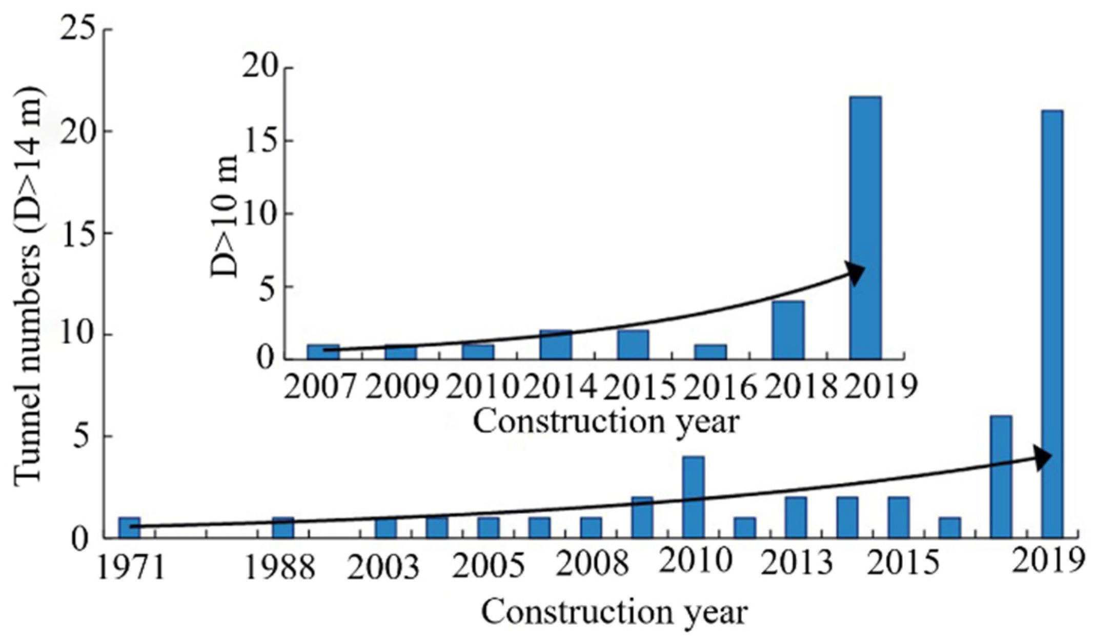
2.1. Tunnel Engineering Background

The tunnel is a single-hole and double-line tunnel with upper and lower floors. The total length of the left line is 1905 m, and the total length of the right line is 2656.96 m. The buried depth of the shield tunnel is approximately 17.9~18.1 m. A super-large-diameter slurry pressure balance (SPB) shield machine with a diameter of 15.80 m is adopted for shield tunneling. The shield machine, with a total length of 167 m, a total weight of about 2500 t, and a maximum propulsion speed of 50 mm/min, starts from the south working well and will be received in the north working well. A series of ring wedge-shaped single-layer segments with an outer diameter of 15.2 m, an inner diameter of 13.9 m, a width of 2 m, and a thickness of 65 cm are adopted in this project.

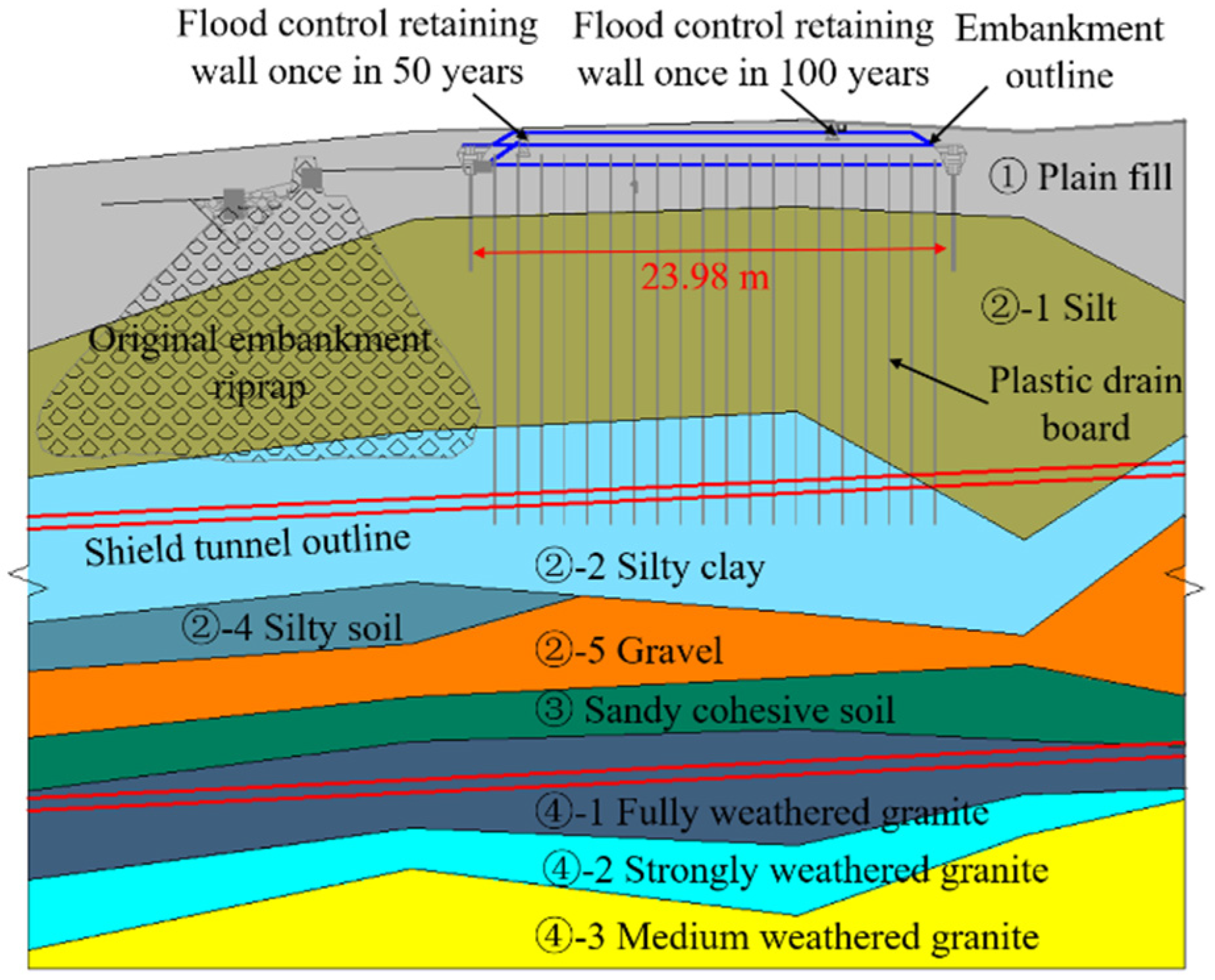
2.2. Upper-Soft and Lower-Hard Strata Characteristics

During the crossing of the shield tunnel through the north bank embankment, the soil layers from top to bottom are plain fill ①, silt ②-1, silty clay ②-2, coarse sand ②-3, silty soil ②-4, gravel ②-5, sandy clay ③, fully weathered granite ④-1, strongly weathered granite ④-2, and moderately weathered granite ④-3. The physical and mechanical parameters corresponding to each soil layer or rock layer are shown in Table 1. Figure 2 shows the longitudinal sections of the shield tunnel crossing the soil layer of the north embankment of the Ma Liuzhou waterway. It can be seen that when the shield tunnel crosses the north embankment, the upper part is distributed with a soft soil layer with low strength, and the lower part is distributed with a granite stratum with high strength and different degrees of weathering, which are the typical characteristics of the upper-soft and lower-hard strata.

3. Numerical Simulation Analysis

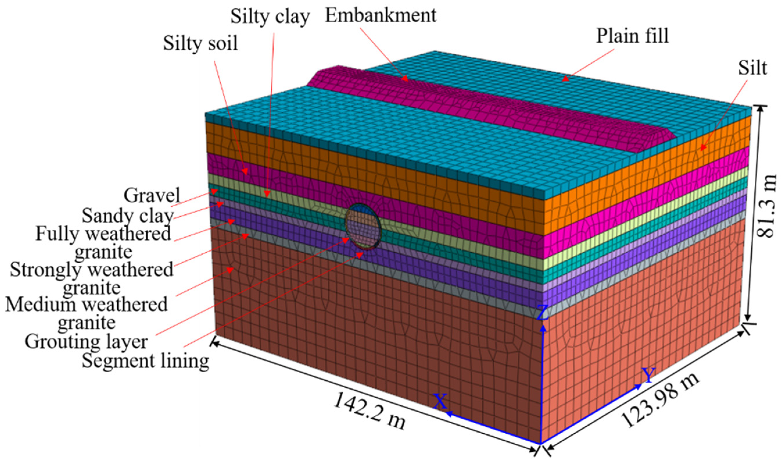
3.1. Model Construction

To better understand the impact of shield tunnel crossing on the embankment, some effective measures may be taken in advance to curb the deformation of the embankment [16]. Finite element software [17] is used to establish a three-dimensional model of the super-large-diameter shield tunnel crossing the north embankment under the upper-soft and lower-hard strata according to actual engineering and stratigraphic information (Figure 3). There are two working situations with and without reinforcement measures that will be simulated. To minimize the influence of the boundary effect of excavation, the left and right boundaries and the lower boundary of the model are set to four times and three times the hole diameter, respectively, while the upper boundary is set to 18.1 m according to the actual buried depth of the shield tunnel. The result is that the entire model with a length of 142.2 m, a width of 123.98 m, and a height of 81.3 m includes a total of 91,104 elements and 62,617 nodes. The three directions (X, Y, and Z) of the bottom surface of the model are all set as displacement constraints, and the top surface (including the top surface of the embankment) is set as a free boundary. The left and right sides of the model are set as the displacement constraints in the X direction, while the front and back are set as the displacement constraints in the Y direction.
The stratum in the whole model is divided into nine layers: the upper six layers are soil layers, and the lower three layers are granite layers. Both the soil and rock layers are arranged to obey the Mohr–Coulomb (M–C) elastoplastic constitutive model. The surrounding rock, segment, grouting layer, and the existing north embankment in the model are all simulated by solid elements. The grouting filling body on the back of the segment is regarded as a homogeneous material with an equal thickness. The support pressure of the tunnel face and the grouting pressure of the grouting layer are performed by means of node-concentrated force in the process of shield tunneling. Table 1 lists the numerical calculation parameters of each layer. Additionally, the segment and grouting layers are given elastic models, and the values of the density, elastic modulus, and Poisson’s ratio of the two materials are shown in Table 2.

3.2. Simulation Conditions and Steps

To investigate the deformation control of the embankment during the process of the shield tunnel crossing the embankment, two working conditions, i.e., reinforced and unreinforced embankment, are studied. The reinforcement range of the embankment, a total width of 25.2 m, is 5 m on both sides of the tunnel side line. The effect of reinforcement is reflected by improving the formation parameters of the reinforcement range. Therefore, there is a comparison over the deformation and failure characteristics of the embankment with and without the reinforced working conditions. The realization process of the numerical simulation of shield excavation mainly includes the following five steps: (1) equilibrating the initial in situ stress field; (2) excavating a soil layer within the width of the segment and applying earth pressure on the face of the tunnel; (3) generating segment elements, grouting body elements, applying grouting pressure, and simultaneously eliminating the earth pressure on the face; (4) removing grouting pressure around the tunnel and turning the grouting element into a hardened grouting element; (5) taking the above four steps as a cycle step and continuing to excavate.

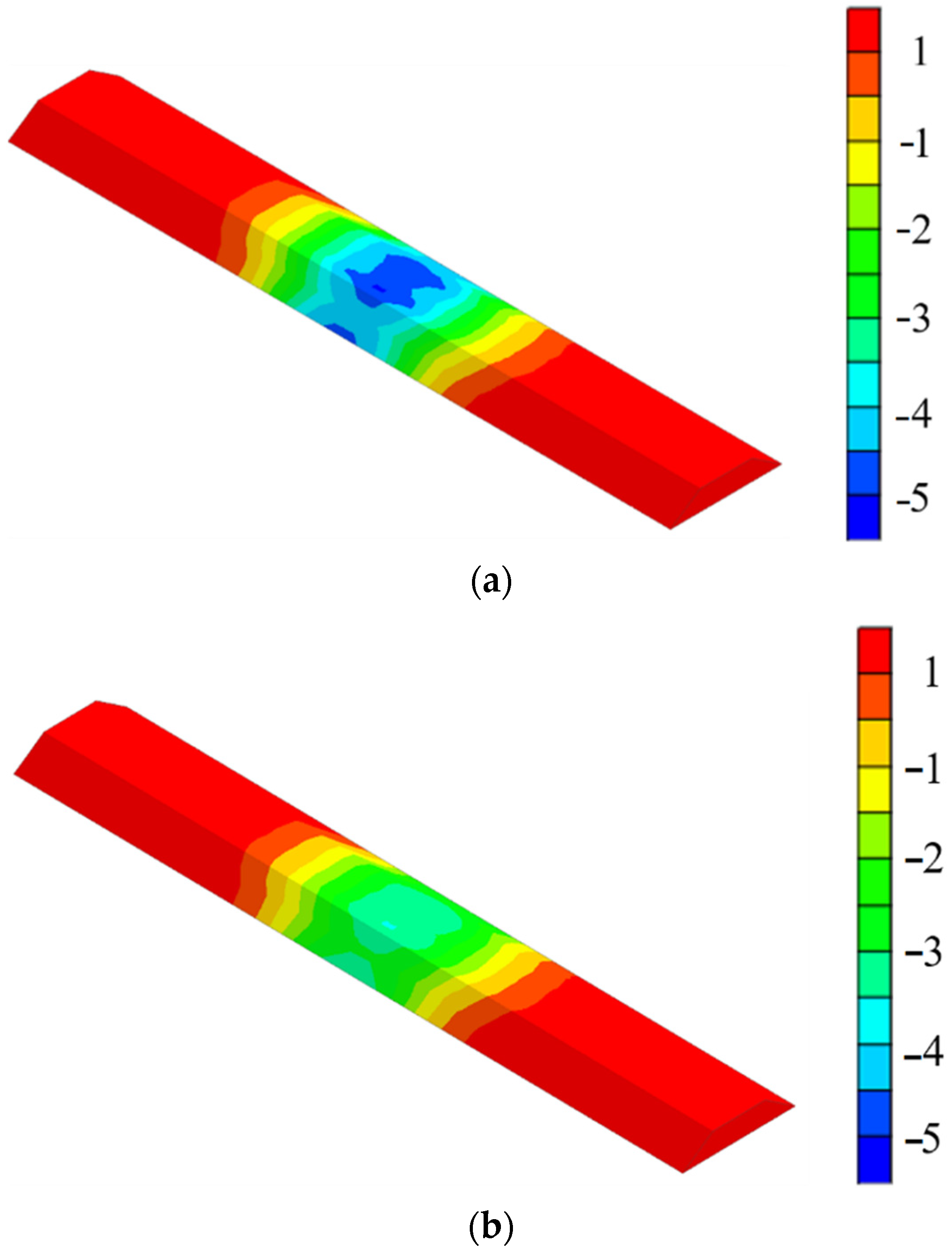
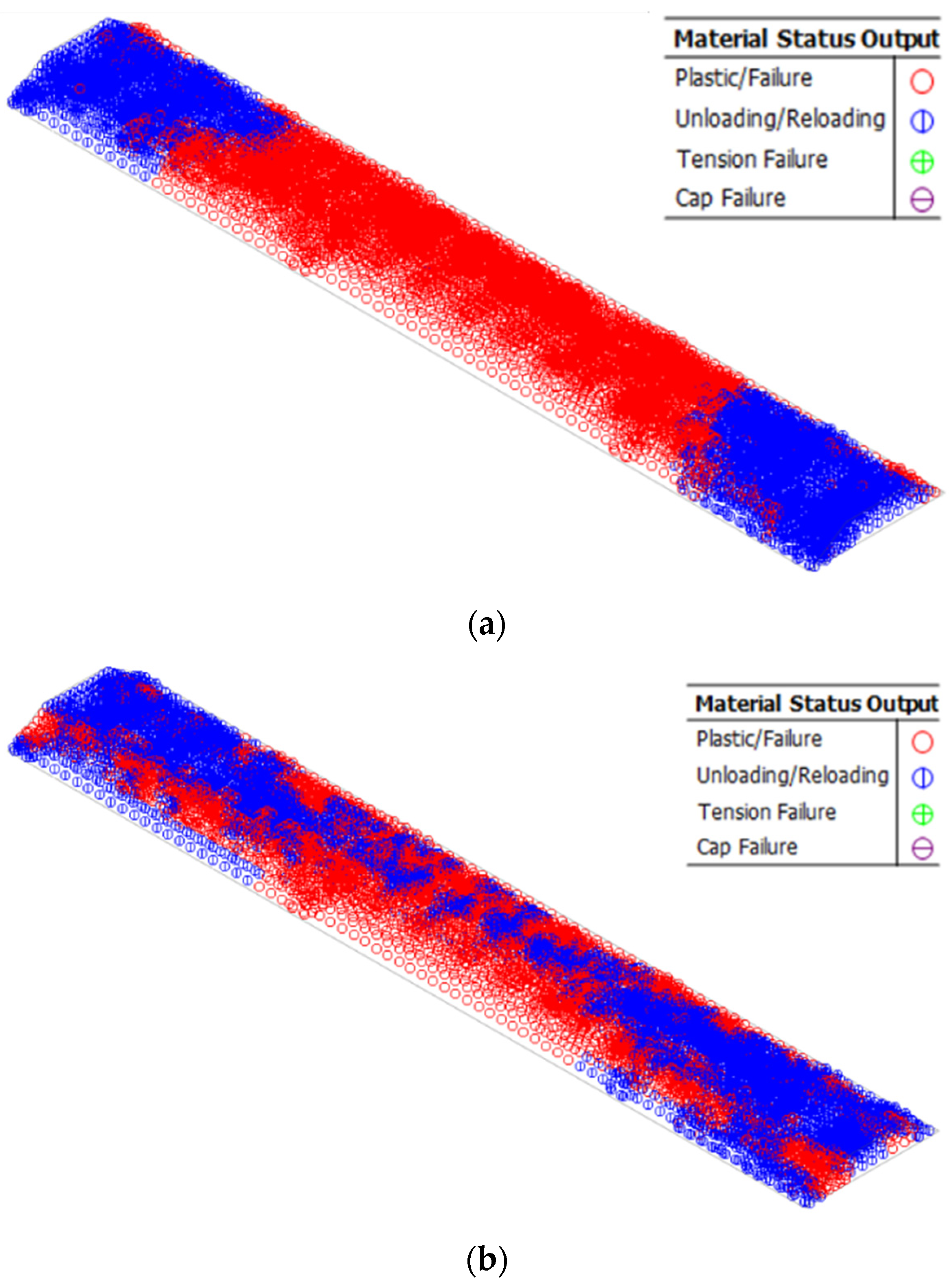
3.3. Numerical Results Analysis

Figure 4 shows the cloud map of the vertical displacement of the embankment with and without reinforcement. It can be seen that prior to the reinforcement, the embankment in the floating position of the shield tunnel exhibits obvious settlement, with a maximum value of 3.85 cm and a significant range of settlements. Encouragingly, after the grouting reinforcement measures are adopted, a remarkable improvement over the settlement value and range of the embankment may be observed, whereby the maximum settlement value declines to 2.46 cm, and the settlement range is significantly reduced.
Figure 5 illustrates the change diagram of the plastic zone of the embankment. From Figure 5, an obvious damage to soil is seen prior to the reinforcement of the embankment. However, when the grouting is applied, the extent of the plastic zone is significantly reduced (see Figure 5b). By comparing the two simulated conditions, it can be found that the settlement of the embankment and the extent of the plastic zone are significantly reduced after the grouting reinforcement measures are taken, which indicates that the effect of grouting reinforcement is promising and remarkable.

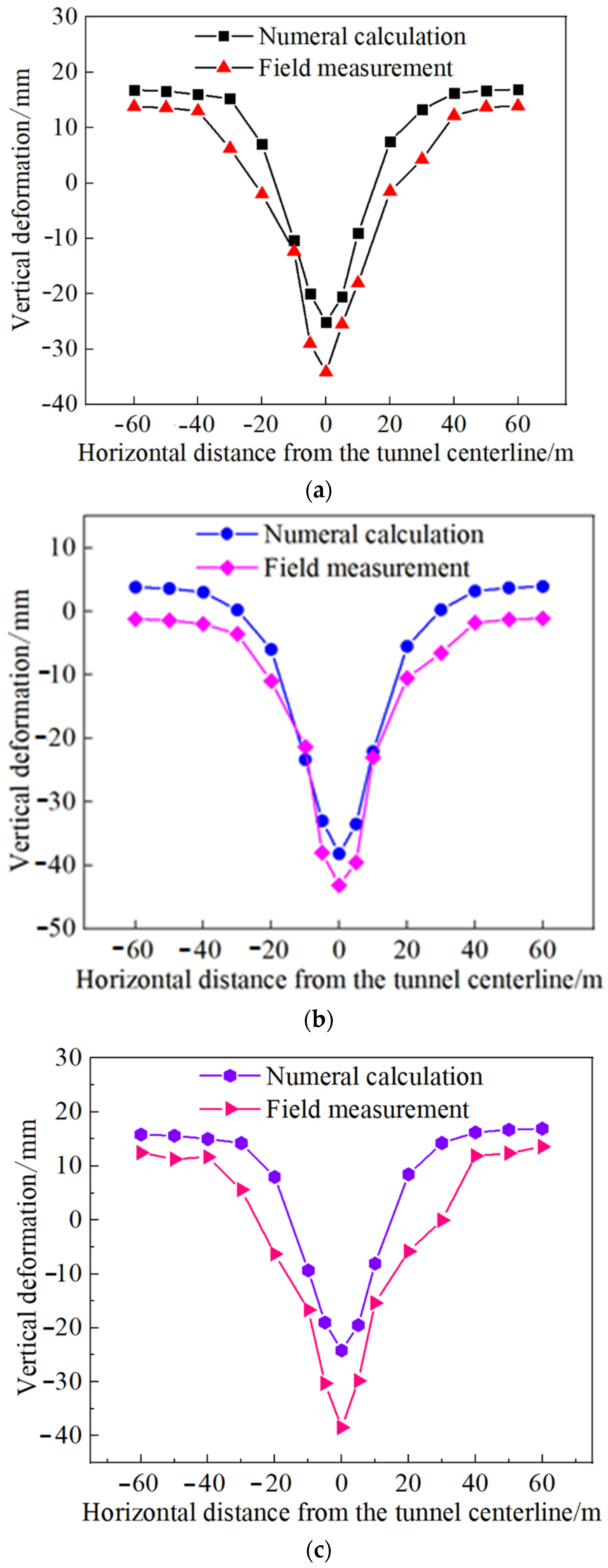
3.4. Comparison of Field Measurement Results with Numerical Results

According to the monitoring and measurement scheme mentioned in the field, the same arrangement is also used in the numerical simulation process. In this section, the variations of the lateral surface deformation trough of the monitoring sections (i.e., DM1, DM2, and DM3) located on the surface of the embankment are provided after the shield tunnel passes through the embankment. Figure 6 presents the lateral surface deformation of DM1, DM2, and DM3 obtained by field measurement and numerical simulation. It can be seen from Figure 6 that the lateral deformation trough of the three sections seems to be described by Gaussian normal distribution. At the position far from the tunnel centerline, an uplifted deformation of the embankment is observed, and a subsidence deformation is seen. The maximum settlement deformation occurs above the central axis of the tunnel. The coverage of the lateral deformation trough is about three times the diameter of the hole on both sides of the tunnel centerline. The numerical simulation is in agreement with the field measurement results, indicating that the aforementioned numerical simulation may truly reflect the actual situation.

4. Conclusions

In this research, the law of settlement deformation of the super-large-diameter shield tunnel crossing the embankment under the conditions of upper-soft and lower-hard strata is investigated, and corresponding security control measures are put forward. The following main conclusions are drawn:
  • The numerical simulation results show that the settlement of the embankment caused by the shield tunneling before the reinforcement is large, and there are potential construction risks. However, the use of grouting reinforcement can effectively minimize the maximum surface settlement value and deformation range.
  • A method for controlling the deformation of the embankment during the construction of the super-large-diameter shield tunnel crossing the embankment is proposed, which can provide a reference for other large-diameter shield tunneling projects in the future.

Author Contributions

Supervision, S.Y.; visualization, J.S.; writing—original draft, J.S.; writing—review and editing, S.Y. All authors have read and agreed to the published version of the manuscript.

Funding

This research was funded by [National Natural Science Foundation of China] grant number [52074021].

Acknowledgments

The work was supported by the National Natural Science Foundation of China (Grant No. 52074021). I would like express my gratitude to all those who helped me during the writing of this paper. A special acknowledgement should be shown to You Shuang, from her lectures I benefited greatly.

Conflicts of Interest

The authors declared no potential conflict of interest with respect to the research, authorship, and/or publication of this paper.

References

  1. Liang, Y.; Chen, X.; Yang, J.; Huang, L.C. Risk analysis and control measures for slurry shield tunneling diagonally under an urban river embankment. Adv. Civ. Eng. 2020, 2020, 8875800. [Google Scholar] [CrossRef]
  2. Zhang, Y.Z.; Wen, Z.Y.; You, G.M.; Liu, N. Difficulties and countermeasures in design and construction of shield tunnels in upper-soft and lower-hard stratum. Tunn. Constr. 2019, 39, 152–159. [Google Scholar]
  3. Wang, Z.; Yao, W.J.; Cai, Y.Q.; Xu, B.; Wei, G. Analysis of ground surface settlement induced by the construction of a large-diameter shallow-buried twin-tunnel in soft ground. Tunn. Undergr. Space Technol. 2019, 83, 520–532. [Google Scholar] [CrossRef]
  4. Huang, X.; Liu, Q.S.; Shi, K.; Pan, Y.; Liu, J.P. Application and prospect of hard rock TBM for deep roadway construction in coal mines. Tunn. Undergr. Space Technol. 2018, 73, 105–126. [Google Scholar] [CrossRef]
  5. Yan, J.T.; Jiang, X.P.; Wang, X.H.; Huo, H.Y.; Liu, B. Study on ultimate supporting force of tunnel excavation face and deformation law in upper-soft lower-hard stratum. Yangtze River 2018, 49, 61–67. [Google Scholar]
  6. Li, W.M.; Ren, H.; Sun, Y.T.; Sha, M.Y.; Zhang, Y.W.; Shi, X.D. Multi-source Settlements Evolution Mechanisms Induced by Tunnel Shielding in Upper-soft and Lower-hard Strata. J. Railw. Eng. Soc. 2020, 37, 78–84. [Google Scholar]
  7. Yang, S.Q.; Miao, C.; Gang, F.; Wang, Y.C.; Meng, B.; Li, Y.H.; Jing, H.W. Physical experiment and numerical modelling of tunnel excavation in slanted upper-soft and lower-hard strata. Tunn. Undergr. Space Technol. 2018, 82, 248–264. [Google Scholar] [CrossRef]
  8. Wu, C.S.; Zhu, Z.D.; Song, S.G.; Zhang, J.; Peng, Y.Y. Ground settlement caused by large-diameter slurry shield during tunnel construction in soft soils. Chin. J. Geotech. Eng. 2019, 41, 169–172. [Google Scholar]
  9. Li, X.; Di, H.G.; Zhou, S.X.; Huo, P.; Huang, Q. Effective method for adjusting the uplifting of shield machine tunneling in upper-soft lower-hard strata. Tunn. Undergr. Space Technol. 2021, 115, 104040. [Google Scholar] [CrossRef]
  10. Guan, F.; Zhang, K.Y. Analysis on embankment settlement caused by undercrossing of shield tunneling. Highway 2017, 62, 293–298. [Google Scholar]
  11. Zhang, W.G.; Li, H.R.; Wu, C.Z.; Li, Y.Q.; Liu, Z.Q.; Liu, H.L. Soft computing approach for prediction of surface settlement induced by earth pressure balance shield tunneling. Undergr. Space 2021, 6, 353–363. [Google Scholar] [CrossRef]
  12. Li, Z.; Chen, Z.Q.; Wang, L.; Zeng, Z.; Gu, D.M. Numerical simulation and analysis of the pile underpinning technology used in shield tunnel crossings on bridge pile foundations. Undergr. Space 2021, 6, 396–408. [Google Scholar] [CrossRef]
  13. Lü, X.; Su, Z.; Huang, M.; Zhou, Y. Strength reduction finite element analysis of a stability of large cross-river shield tunnel face with seepage. Eur. J. Environ. Civ. Eng. 2020, 24, 336–353. [Google Scholar] [CrossRef]
  14. Lin, C.G.; Huang, M.S.; Nadim, F.; Liu, Z.Q. Embankment responses to shield tunnelling considering soil-structure interaction: Case studies in Hangzhou soft ground. Tunn. Undergr. Space Technol. 2020, 96, 103230. [Google Scholar] [CrossRef]
  15. Qi, Y.; Wei, G.; Xie, Y. Effect of Grouting Reinforcement on Settlement of Existing Tunnels: Case Study of a New Crossing Underpass. Symmetry 2021, 13, 482. [Google Scholar] [CrossRef]
  16. Bao, X.K.; Cao, J.X.; Duan, D.M.; Zhao, J.C.; Wu, J.W. Application of Midas/GTS in soft rock tunnel construction design. Highway 2019, 64, 321–325. [Google Scholar]
  17. Sun, Y.; Liu, X. Stability analysis and design optimization of cutting slope in coal measure. Yangtze River 2020, 51, 104–107. [Google Scholar]
Figure 1. Current status of river/sea construction of large-diameter shield tunnels in China in recent years [1].
Applsci 12 04324 g001
Figure 2. The longitudinal section of the tunnel crossing the north embankment.
Applsci 12 04324 g002
Figure 3. 3D numerical model.
Applsci 12 04324 g003
Figure 4. Vertical displacement cloud map of the embankment: (a) without reinforcement and (b) with reinforcement. (Unit: cm.)
Applsci 12 04324 g004
Figure 5. Embankment plastic zone map: (a) without reinforcement and (b) with reinforcement.
Applsci 12 04324 g005
Figure 6. Numerical simulation and field monitoring results of lateral surface deformation characteristics of DM1, DM2, and DM3 sections: (a) DM1 section result, (b) DM2 section result, and (c) DM3 section result.
Applsci 12 04324 g006
Table 1. Basic physical and mechanical parameters of rock and soil.
Stratum NumberStratumThickness/mDensity/g⋅cm−3Moisture
Content/%
Deformation Modulus/MPaPoisson RatioCohesion/
kPa
Friction
Angle/°
Plain fill1.0~5.01.7123.8-0.1814.026.9
②-1Silt5.2~16.71.6063.91.80.4015.013.0
②-2Silty clay2.0~18.01.9228.44.80.303517.4
②-3Coarse sand0.9~13.02.64--0.26-30
②-4Silty soil1.1~19.21.74462.30.391816.2
②-5Gravel0.8~19.219.0-40.00.25-35.0
Sandy clay1.4~16.51.8824.54.90.252923.2
④-1Fully weathered granite1.1~25.01.9120.9890.302623.0
④-2Strongly weathered granite0.2~7.52.00-1600.233525
④-3Moderately weathered granite6.0~7.42.81-20000.2040033
Table 2. Model parameters of the grouting layer and segment.
MaterialsDensity/(kg·m−3)Elastic Modulus/GPaPoisson’s Ratio
Segment250034.5/36.50.167
Grouting layer20002 × 10−30.25
Publisher’s Note: MDPI stays neutral with regard to jurisdictional claims in published maps and institutional affiliations.

