
Suppression of Harmonic Current in Magnetic Bearing–Rotor System with Redundant Structure


Abstract
:1. Introduction
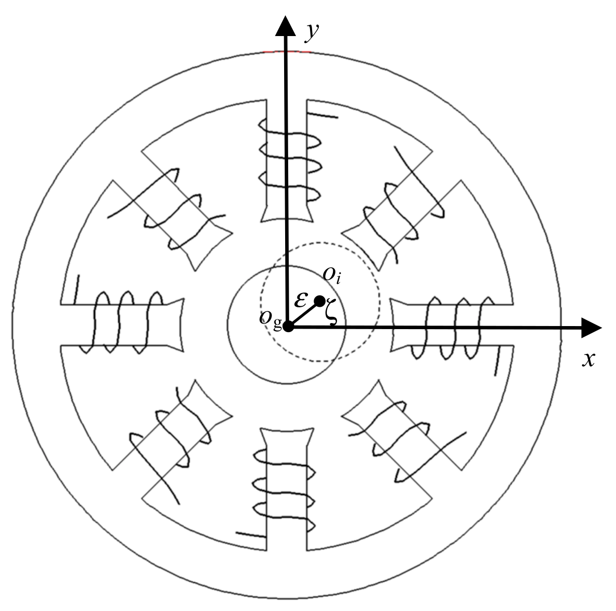
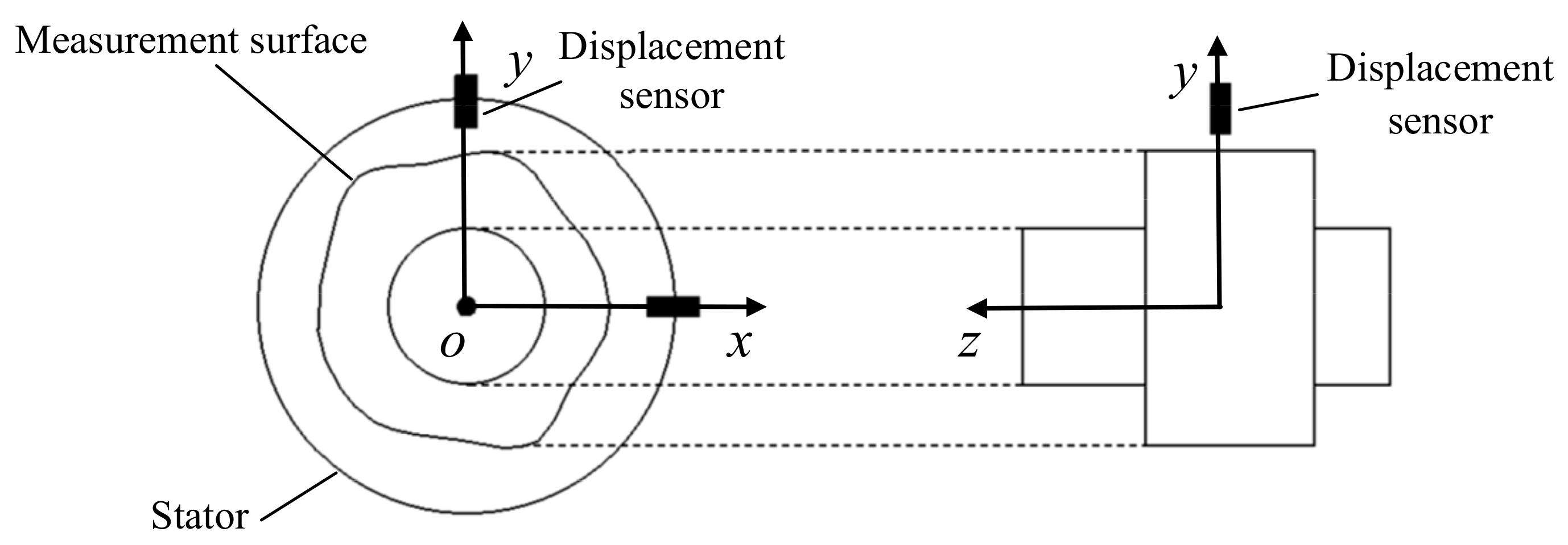
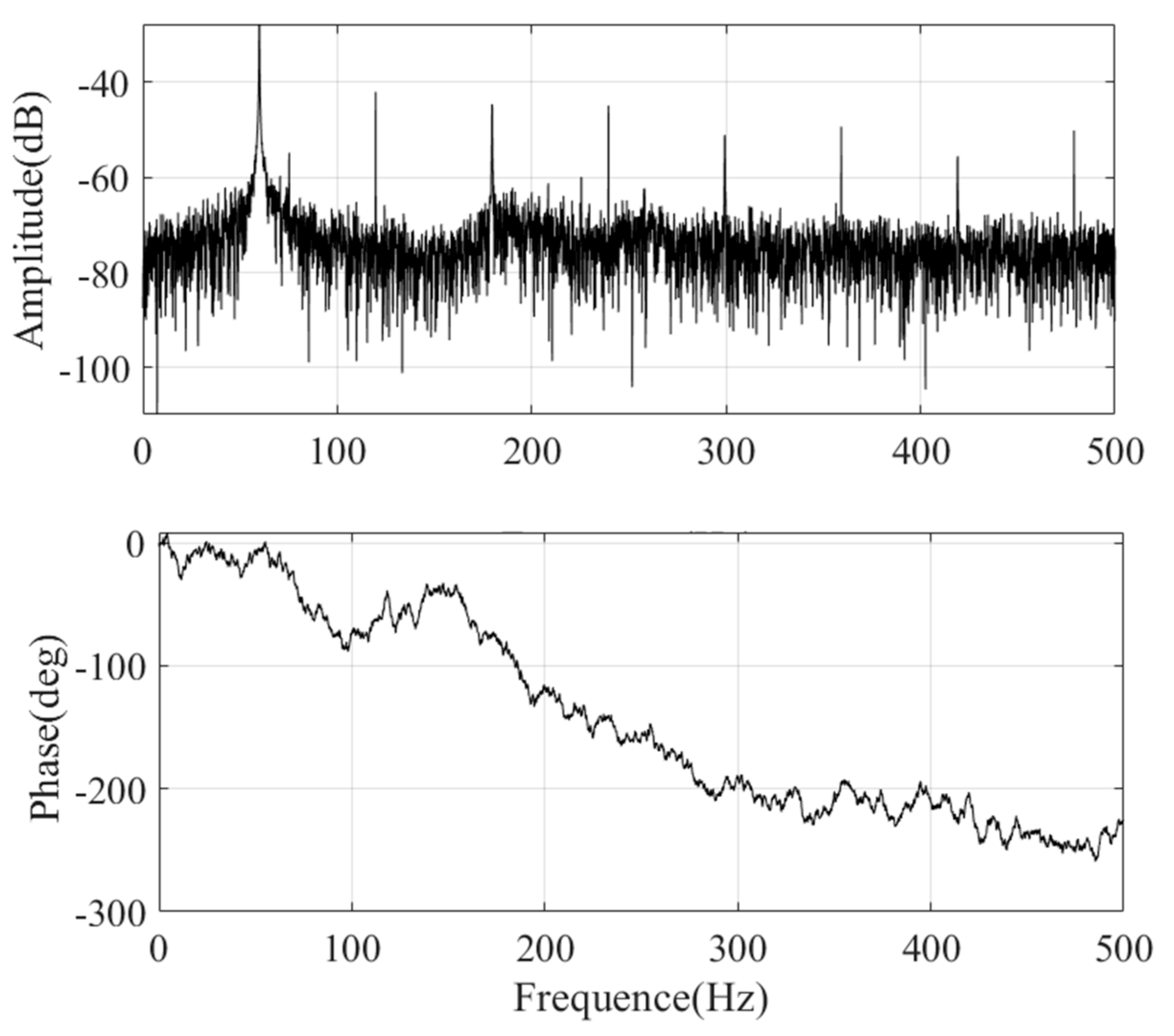
2. Mode of Mass Unbalance and Sensor Runout
3. Characteristic and Control Strategy of Magnetic Bearings with Redundant Structures
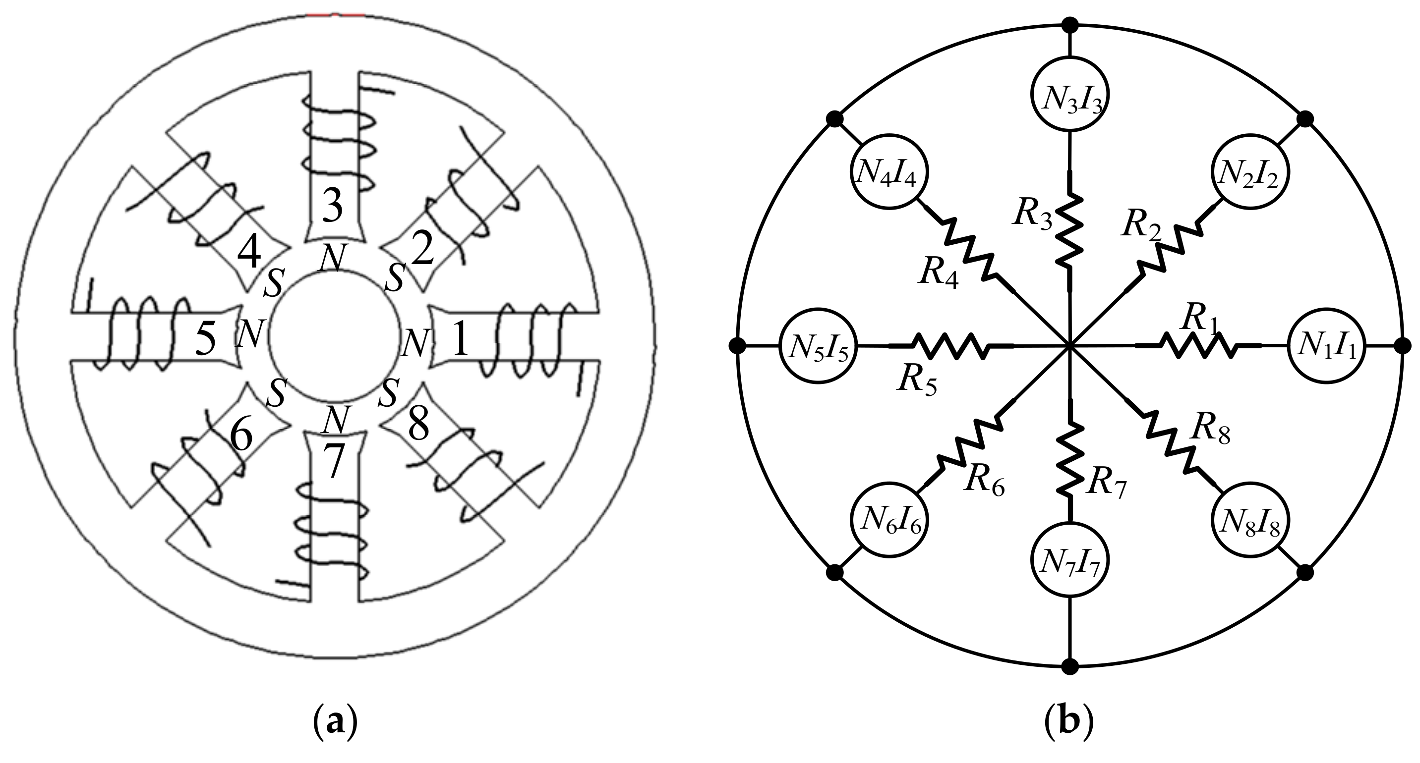
3.1. Force Mode of Eight-Pole Magnetic Bearings with Redundant Structures
3.2. Stiffness of Magnetic Bearing with Redundant Structures
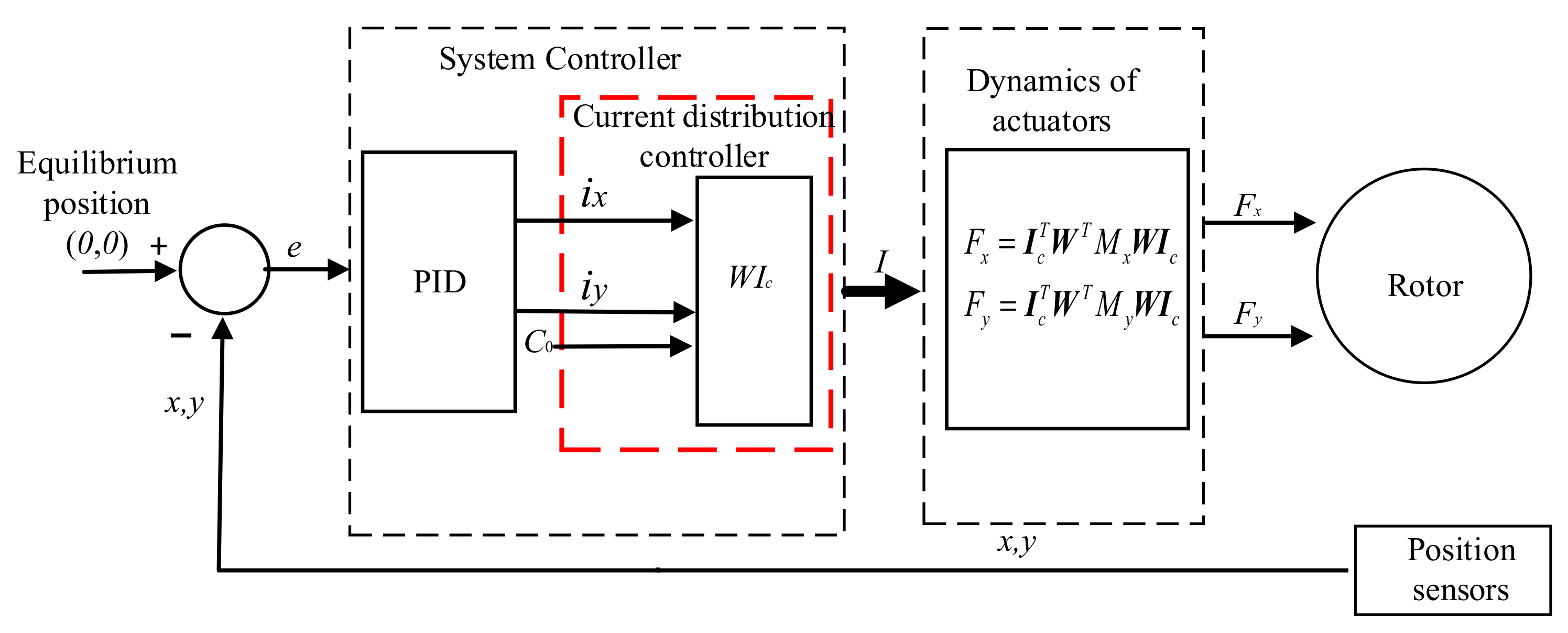
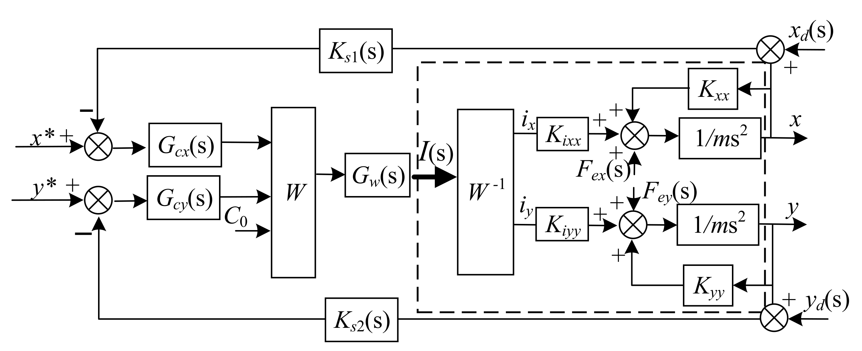
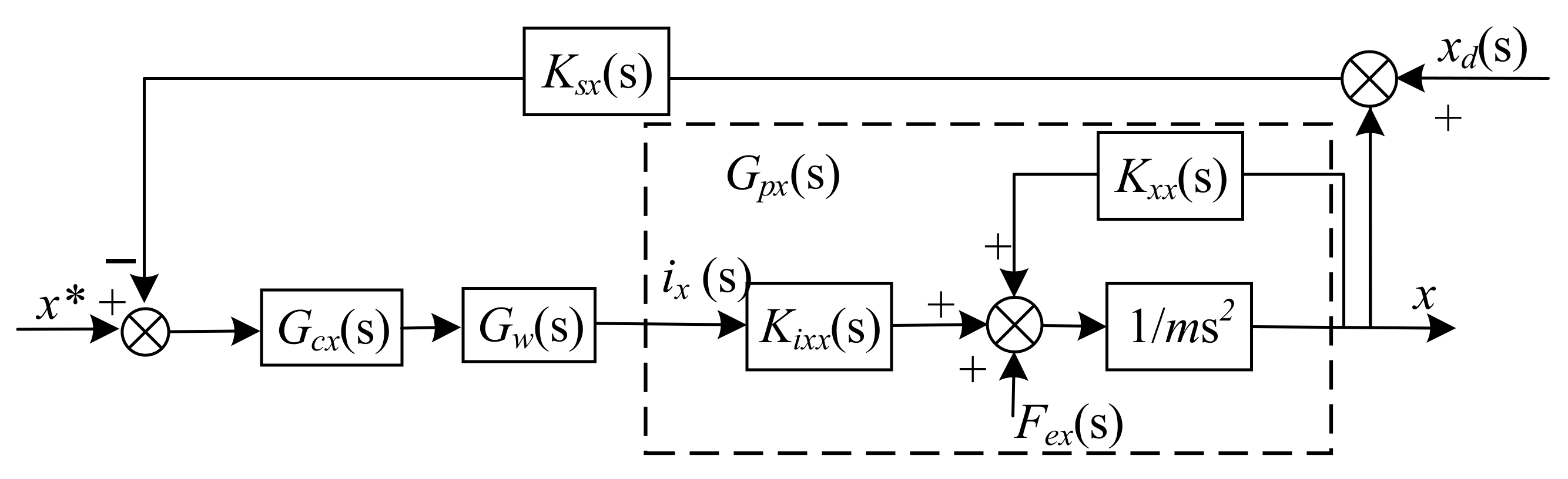
3.3. Control Strategy and Analysis of Magnetic Bearings with Redundant Structures
4. Suppression of Harmonic Current in AMB with Redundant Structures
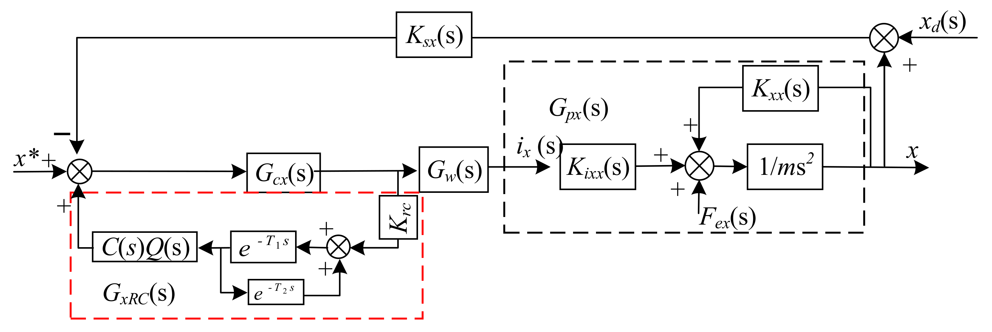
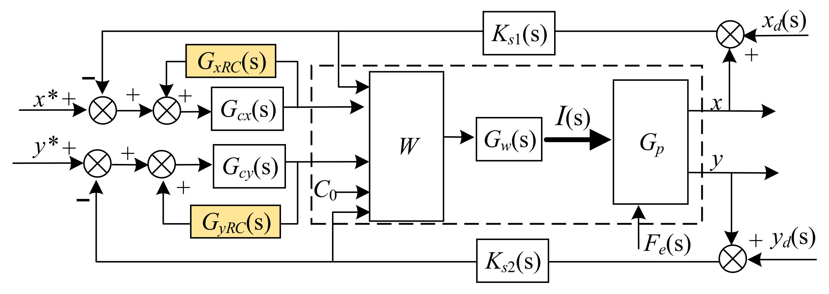
4.1. Analysis of Magnetic Bearing System with RC
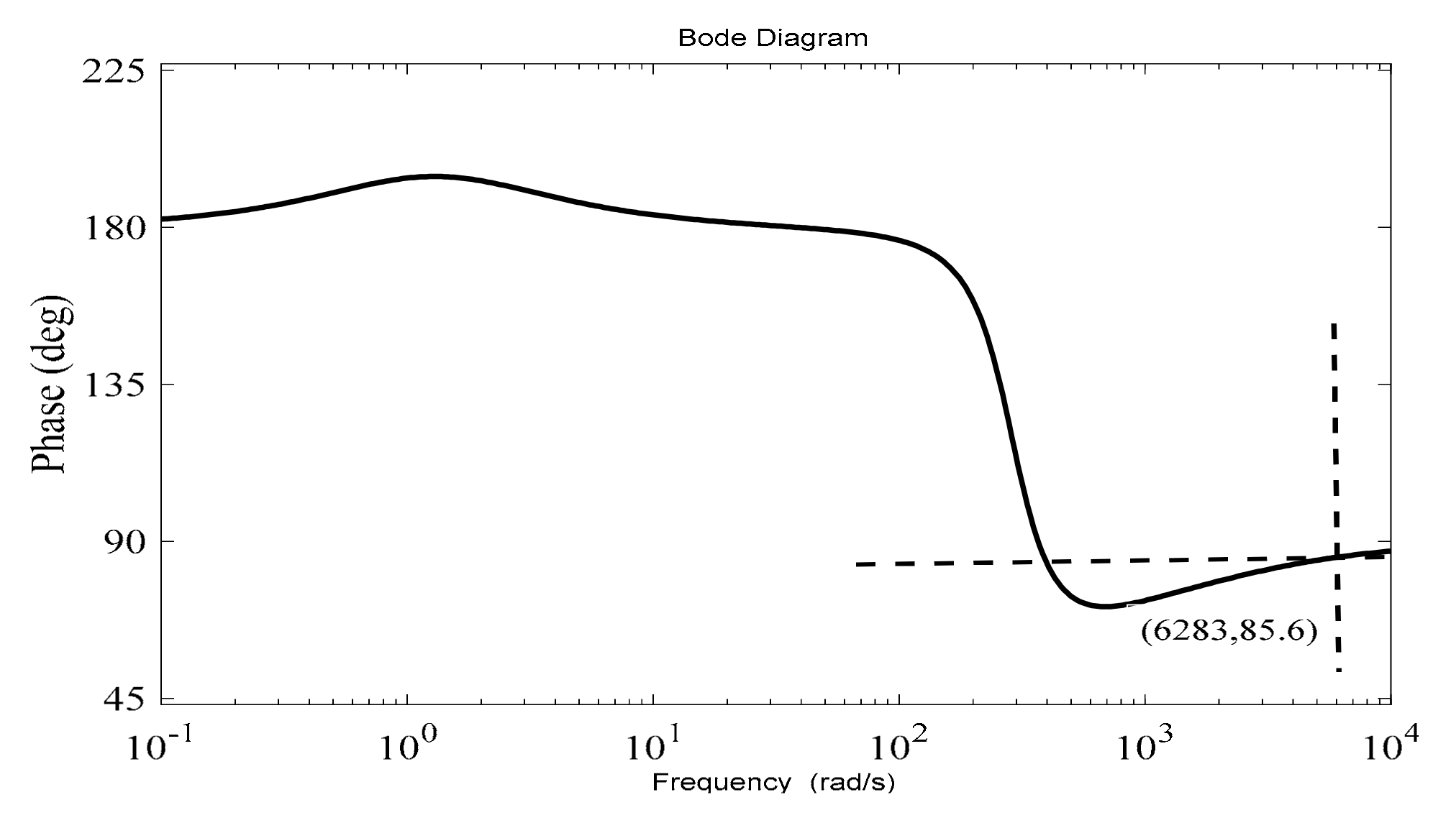
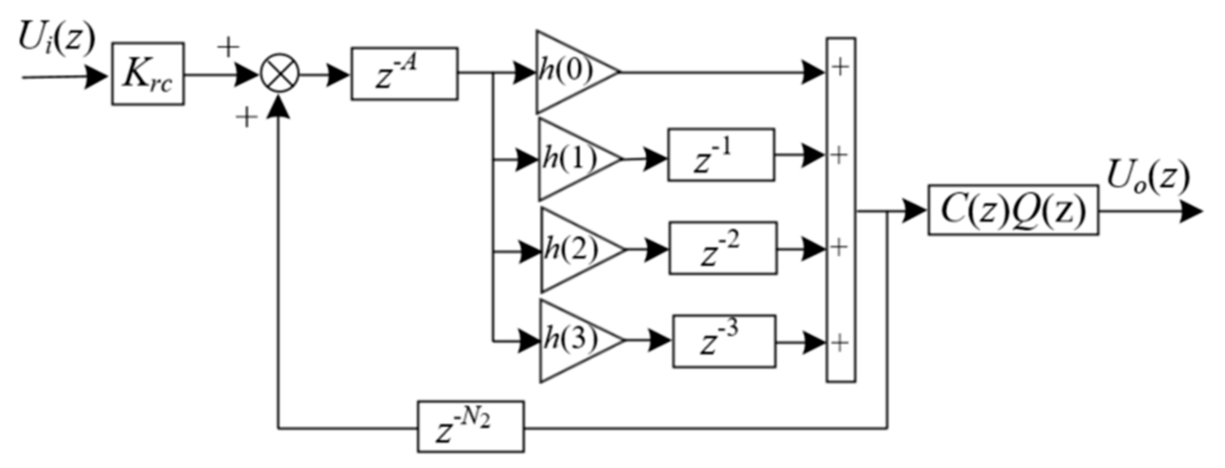
4.2. Design of the RC for AMB with Redundant Structures
- (a)
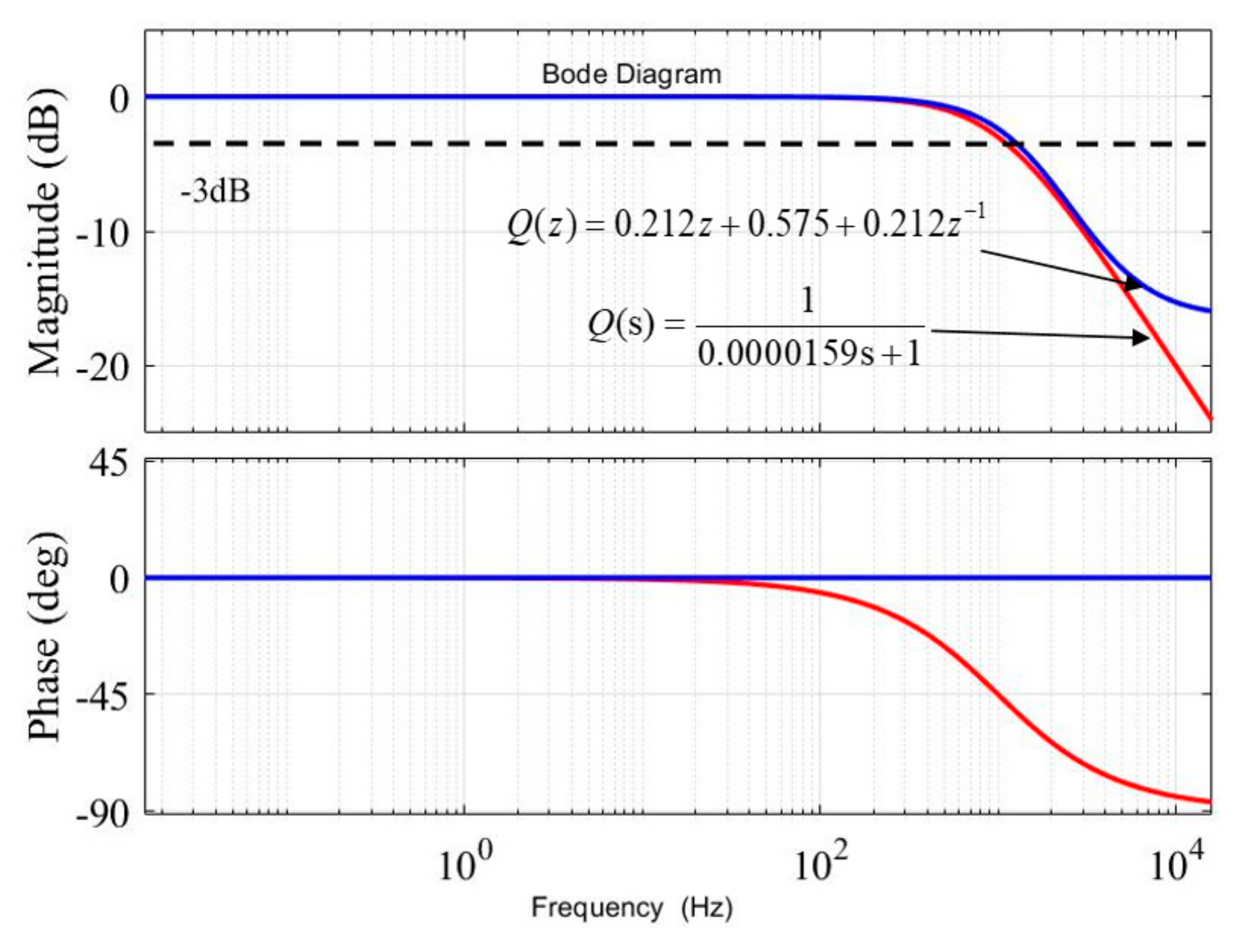
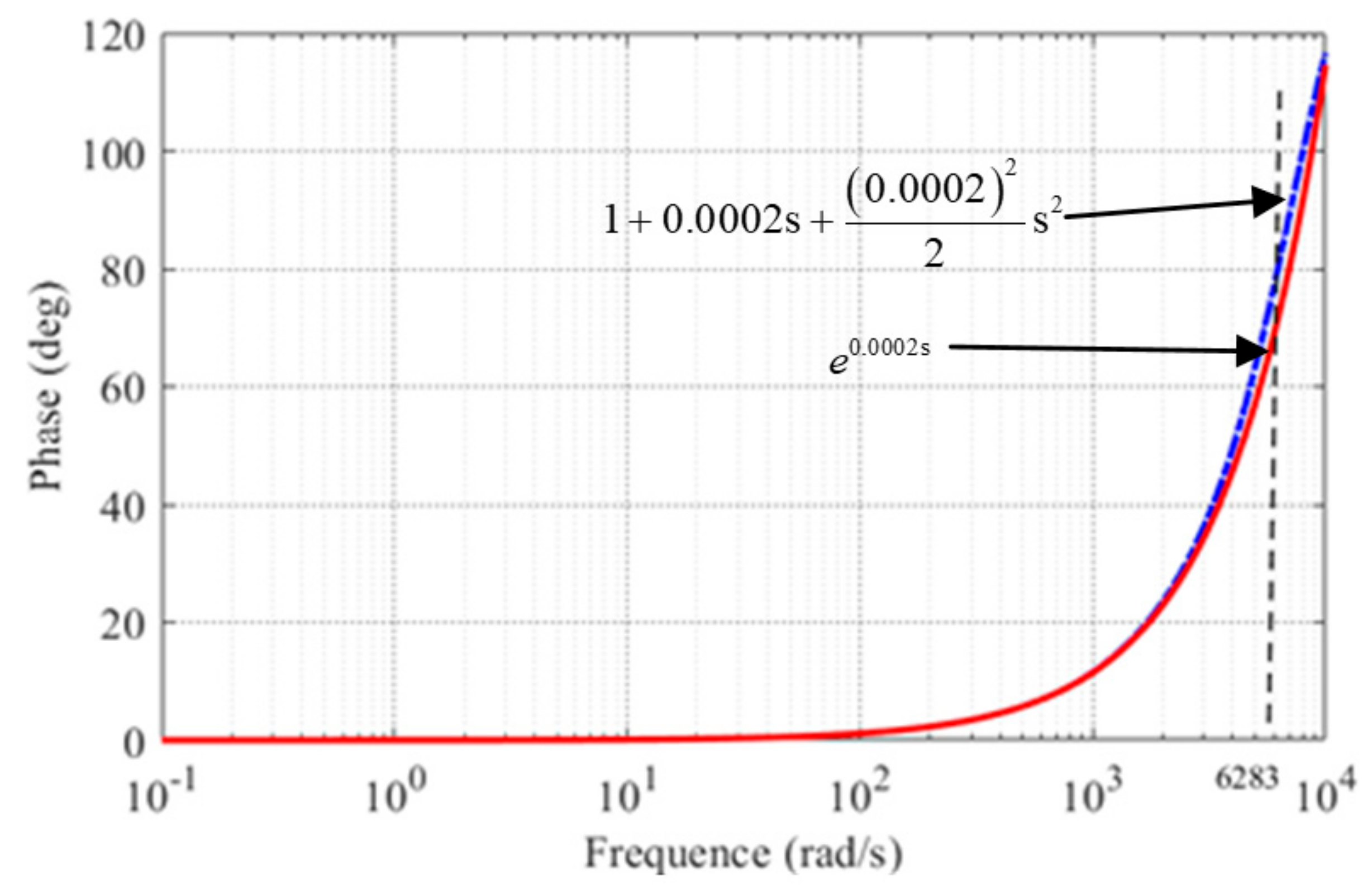
- Design of for F(s) in high-frequency domain
- (b)
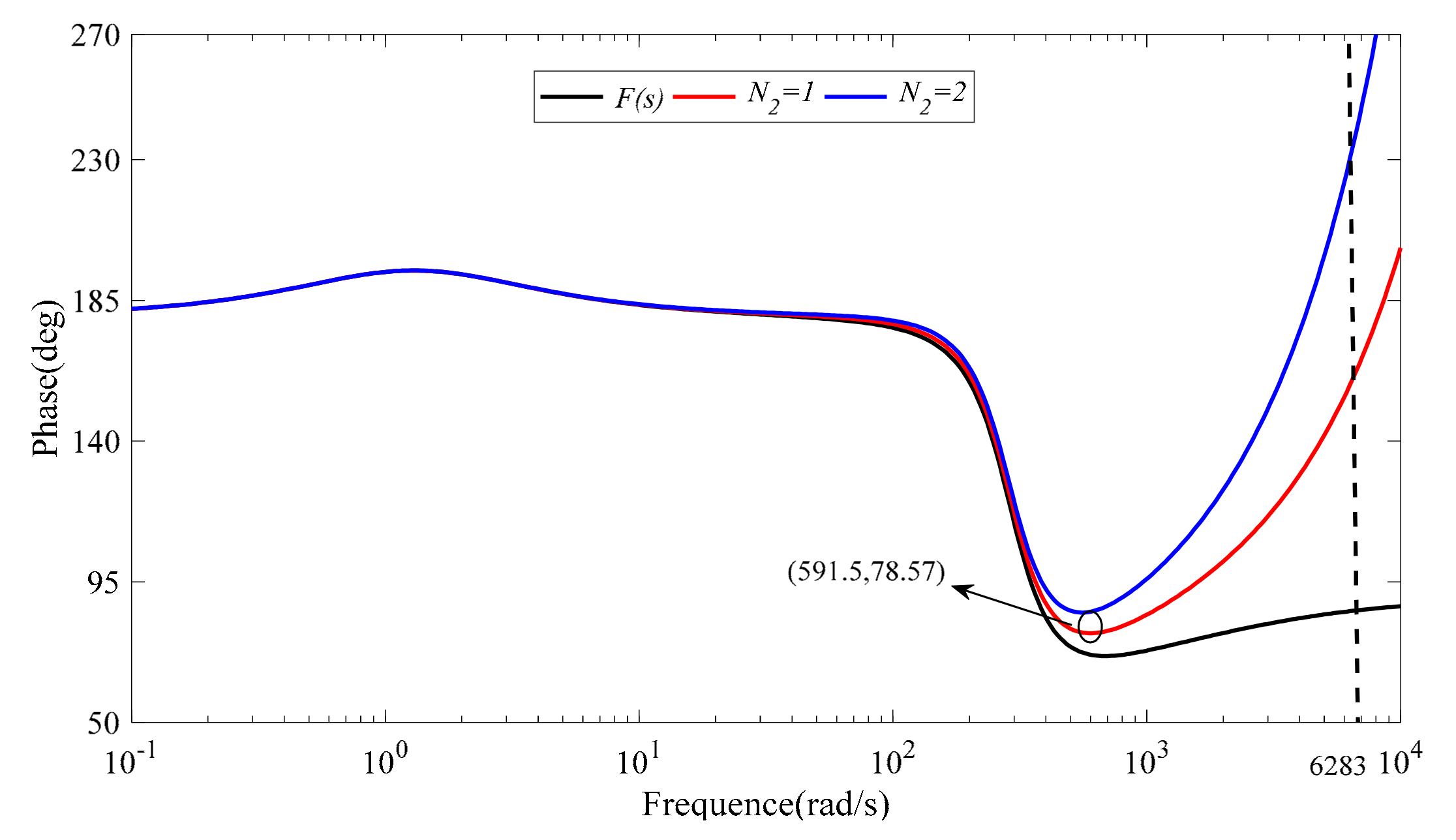
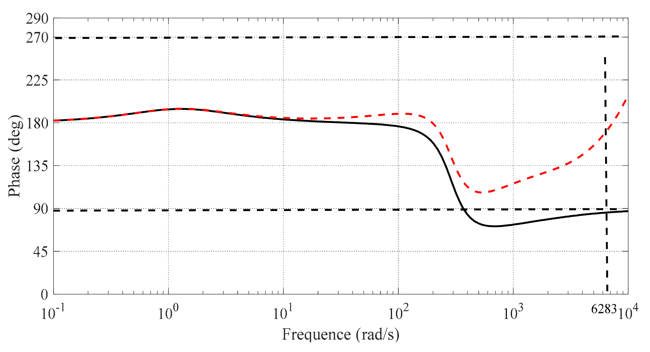
- Design of for F(s) in the middle-frequency domain
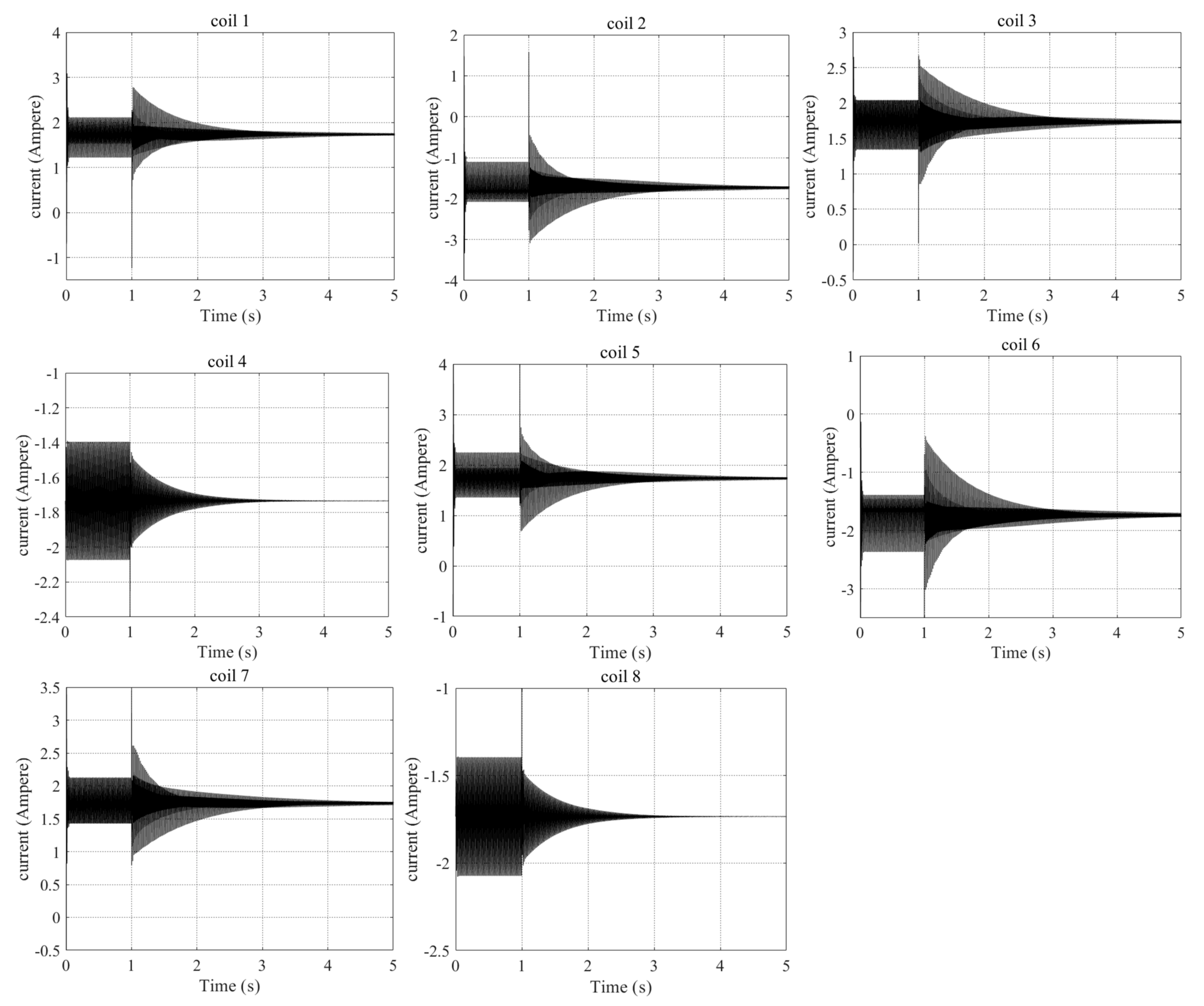
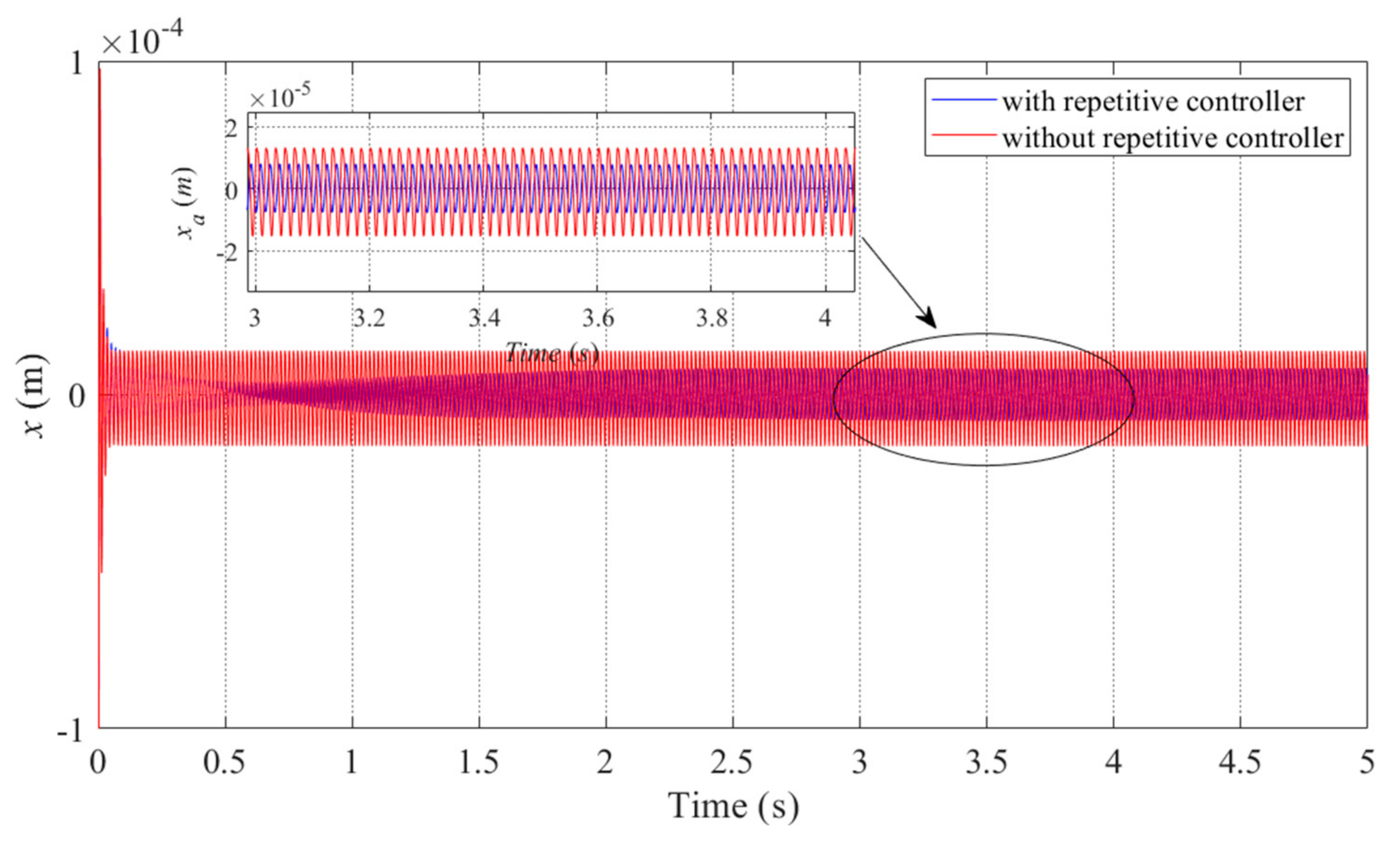
4.3. Simulation Verification and Analysis
5. Conclusions
Author Contributions
Funding
Institutional Review Board Statement
Informed Consent Statement
Data Availability Statement
Conflicts of Interest
References
- Allaire, P.E.; Fittro, R.L.; Maslen, E.H.; Wakefield, W.C. Measured Force/Current Relations in Solid Magnetic Thrust Bearings. J. Eng. Gas Turbines Power 1997, 119, 137–142. [Google Scholar] [CrossRef]
- Keogh, P.; Cole, M.O.T. Dynamics and Control Issues for Fault Tolerance. In Magnetic Bearings; Schweitzer, G., Maslen, E.H., Eds.; Springer: Berlin/Heidelberg, Germany, 2009; pp. 407–433. [Google Scholar]
- Park, Y. Design and implementation of an electromagnetic levitation system for active magnetic bearing wheels. IET Control Theory Appl. 2014, 8, 139–148. [Google Scholar] [CrossRef]
- Ren, Y.; Fang, J. High-Precision and Strong-Robustness Control for an MSCMG Based on Modal Separation and Rotation Motion Decoupling Strategy. IEEE Trans. Ind. Electron. 2013, 61, 1539–1551. [Google Scholar] [CrossRef]
- Cheng, X.; Wang, B.; Chen, Q.; Zhang, L.; Liu, H.; Song, S. A unified design and the current ripple characteristic analysis of digital switching power amplifier in active magnetic-levitated bearings. Int. J. Appl. Electromagn. Mech. 2017, 55, 391–407. [Google Scholar] [CrossRef]
- Maslen, E.H.; Meeker, D.C. Fault tolerance of magnetic bearings by generalized bias current linearization. IEEE Trans. Magn. 1995, 31, 2304–2314. [Google Scholar] [CrossRef] [Green Version]
- Na, U.J.; Palazzolo, A. Optimized Realization of Fault-Tolerant Heteropolar Magnetic Bearings. J. Vib. Acoust. 2000, 122, 209–221. [Google Scholar] [CrossRef] [Green Version]
- Na, U.J.; Palazzolo, A.B.; Provenza, A. Test and Theory Correlation Study for a Flexible Rotor on Fault-Tolerant Magnetic Bearings. J. Vib. Acoust. 2002, 124, 359–366. [Google Scholar] [CrossRef]
- Noh, M.D.; Cho, S.-R.; Kyung, J.-H.; Ro, S.-K.; Park, J.-K. Design and implementation of a fault-tolerant magnetic bearing system for Tur-bo-Molecular Vacuum Pump. IEEE-ASME Trans. Mechatron. 2005, 10, 626–631. [Google Scholar] [CrossRef]
- Na, U.J.; Palazzolo, A. Fault tolerance of magnetic bearings with material path reluctances and fringing factors. IEEE Trans. Magn. 2000, 36, 3939–3946. [Google Scholar] [CrossRef] [Green Version]
- Na, U.J. Fault tolerant control of magnetic bearings with force invariance. J. Mech. Sci. Technol. 2005, 19, 731–742. [Google Scholar] [CrossRef]
- Na, U.J. Fault tolerant homopolar magnetic bearings with flux invariant control. J. Mech. Sci. Technol. 2006, 20, 643–651. [Google Scholar] [CrossRef]
- Meeker, D. A Generalized Unbiased Control Strategy for Radial Magnetic Bearings. Actuators 2017, 6, 1. [Google Scholar] [CrossRef] [Green Version]
- Xin, C.; Baixin, C.; Han, L.; Allen, G.M. An Accurate Linearization of Electromagnetic Force of Heteropolar Magnetic Bearings With Redundant Structures. J. Eng. Gas Turbines Power 2020, 142, 091002. [Google Scholar] [CrossRef]
- Cheng, B.; Cheng, X.; Song, S.; Deng, S.; Zhou, R.; Hu, Y.; Wu, H. Fault-Tolerant Control of Magnetically-Levitated Rotor with Re-dundant Structures Based on Improved Generalized Linearized EMFs Model. Sensors 2021, 21, 5404. [Google Scholar] [CrossRef]
- Meeker, D.; Maslen, E. A Parametric Solution to the Generalized Bias Linearization Problem. Actuators 2020, 9, 14. [Google Scholar] [CrossRef] [Green Version]
- Cheng, X.; Deng, S.; Cheng, B.; Lu, M.; Zhou, R. Optimization of bias current coefficient in the fault-tolerance of active magnetic bearings based on the redundant structure parameters. Automatika 2020, 61, 602–613. [Google Scholar] [CrossRef]
- Cheng, X.; Deng, S.; Cheng, B.-X.; Hu, Y.-F.; Wu, H.-C.; Zhou, R.-G. Design and Implementation of a Fault-Tolerant Magnetic Bearing Control System Combined With a Novel Fault-Diagnosis of Actuators. IEEE Access 2020, 9, 2454–2465. [Google Scholar] [CrossRef]
- Mao, C.; Zhu, C. A real-time variable step size iterative unbalance compensation for active magnetic bearing-rigid rotor systems. Proc. Chin. Soc. Elect. Eng. 2018, 38, 3960–3968. [Google Scholar] [CrossRef]
- Jian, Z.; Huachun, W.; Weiyu, W.; Kezhen, Y.; Yefa, H.; Xinhua, G.; Chunsheng, S. Online unbalance compensation of a maglev rotor with two active magnetic bearings based on the LMS algorithm and the influence coefficient method. Mech. Syst. Signal Process. 2021, 166, 108460. [Google Scholar] [CrossRef]
- Cui, P.; Sheng, L.; Zhao, G.; Peng, C. Suppression of Harmonic Current in Active–Passive Magnetically Suspended CMG Using Improved Repetitive Controller. IEEE/ASME Trans. Mechatron. 2016, 21, 2132–2141. [Google Scholar] [CrossRef]
- Cui, P.; Wang, Q.; Zhang, G.; Gao, Q. Hybrid Fractional Repetitive Control for Magnetically Suspended Rotor Systems. IEEE Trans. Ind. Electron. 2017, 65, 3491–3498. [Google Scholar] [CrossRef]
- Cai, K.; Deng, Z.; Peng, C.; Li, K. Suppression of Harmonic Vibration in Magnetically Suspended Centrifugal Compressor Using Zero-Phase Odd-Harmonic Repetitive Controller. IEEE Trans. Ind. Electron. 2019, 67, 7789–7797. [Google Scholar] [CrossRef]
- Cui, P.; Du, L.; Zhou, X.; Li, J.; Li, Y.; Wu, Y. Harmonic vibration moment suppression using hybrid repetitive control for active magnetic bearing system. J. Vib. Control 2021, 1–14. [Google Scholar] [CrossRef]
- Cui, P.; Li, S.; Wang, Q.; Gao, Q.; Cui, J.; Zhang, H. Harmonic Current Suppression of an AMB Rotor System at Variable Rotation Speed Based on Multiple Phase-Shift Notch Filters. IEEE Trans. Ind. Electron. 2016, 63, 6962–6969. [Google Scholar] [CrossRef]
- He, J.; Peng, C.; Deng, Z.; Zhu, M. Comparison of AMB-rotor system using multiple phase-shift notch filters connected in series and parallel modes for vibration control. In Proceedings of the 2018 Chinese Control And Decision Conference (CCDC), Shenyang, China, 9–11 June 2018; pp. 348–353. [Google Scholar]
- Cui, P.; Du, L.; Zhou, X.; Li, J.; Li, Y.; Wu, Y. Harmonic Vibration Control of MSCMG Based on Multisynchronous Rotating Frame Transformation. IEEE Trans. Ind. Electron. 2021, 69, 1717–1727. [Google Scholar] [CrossRef]
- Jin, C.; Guo, K.; Xu, Y.; Cui, H.; Xu, L. Design of Magnetic Bearing Control System Based on Active Disturbance Rejection Theory. J. Vib. Acoust. 2018, 141, 011009. [Google Scholar] [CrossRef]
- Ran, S.; Hu, Y.; Wu, H. Design, modeling, and robust control of the flexible rotor to pass the first bending critical speed with active magnetic bearing. Adv. Mech. Eng. 2018, 10, 1687814018757536. [Google Scholar] [CrossRef]
- Zhang, H.; Liu, J.; Zhu, R.; Chen, H.; Yuan, H. Nonlinear Adaptive Harmonics Vibration Control for Active Magnetic Bearing System With Rotor Unbalance and Sensor Runout. IEEE Sens. J. 2021, 21, 12245–12254. [Google Scholar] [CrossRef]
- Gallego, G.B.; Rossini, L.; Achtnich, T.; Araujo, D.M.; Perriard, Y. Novel Generalized Notch Filter for Harmonic Vibration Suppression in Magnetic Bearing Systems. IEEE Trans. Ind. Appl. 2021, 57, 6977–6987. [Google Scholar] [CrossRef]
- Sun, X.; Jin, Z.; Chen, L.; Yang, Z. Disturbance rejection based on iterative learning control with extended state observer for a four-degree-of-freedom hybrid magnetic bearing system. Mech. Syst. Signal Process. 2021, 153, 107465. [Google Scholar] [CrossRef]


| Structure Parameter | Value | Unit |
|---|---|---|
| Pole area, A0 | 5.4 × 10⁻⁵ | m2 |
| Turns per coil, | 56 | / |
| Pole initial gap, g0 | 4 × 10⁻⁴ | m |
| Pole angle, θj | (j − 1)π/4 | rad |
| Saturation magnetic-flux density, Bsat Rotor weight, m | 1.2 0.8 | T kg |
| Parameter | Value | Parameter | Value |
|---|---|---|---|
| 41 μm | −17.83° | ||
| 7.9 μm | −52.36° | ||
| 5.8 μm | −87.28° | ||
| 5.7 μm | −165.5° | ||
| 2.7 μm | −192.4° | ||
| 3.4 μm | −201° | ||
| 10 μm | −17.83° |
Publisher’s Note: MDPI stays neutral with regard to jurisdictional claims in published maps and institutional affiliations. |
© 2022 by the authors. Licensee MDPI, Basel, Switzerland. This article is an open access article distributed under the terms and conditions of the Creative Commons Attribution (CC BY) license (https://creativecommons.org/licenses/by/4.0/).
Share and Cite
Cheng, B.; Cheng, X.; Song, S.; Zhou, R.; Deng, S. Suppression of Harmonic Current in Magnetic Bearing–Rotor System with Redundant Structure. Appl. Sci. 2022, 12, 4126. https://doi.org/10.3390/app12094126
Cheng B, Cheng X, Song S, Zhou R, Deng S. Suppression of Harmonic Current in Magnetic Bearing–Rotor System with Redundant Structure. Applied Sciences. 2022; 12(9):4126. https://doi.org/10.3390/app12094126
Chicago/Turabian StyleCheng, Baixin, Xin Cheng, Shao Song, Rougang Zhou, and Shuai Deng. 2022. "Suppression of Harmonic Current in Magnetic Bearing–Rotor System with Redundant Structure" Applied Sciences 12, no. 9: 4126. https://doi.org/10.3390/app12094126