1. Introduction
This project was conducted during the time that new parachute equipment was being introduced into the Armed Forces of the Slovak Republic. Its objective was the verification of the functionality and reliability of this personal airborne equipment backpack, the TL-98, before its introduction into parachute operations as well as the acquiring of information applicable to the definition of the TL-98’s rope lifetime. The rope is utilized for the dropping of the TL-98. Due to lack of information about the influence of TL-98 falls on the rope and the TL-98’s functionality and reliability, a program and method for the research activities was elaborated. The newly collected information was applied by defining the TL-98’s rope lifetime in the frame of its maximum number of uses in live parachute operations. These specifications were added to the user manual for the TL-98 for the Armed Forces of the Slovak Republic. Within the scope of the ground and flight research, we conducted a search for the influence of force effects that stopped parachute TL-98 on the rope by which TL-98 was anchored to a firm point (during ground tests) or anchored to the parachute equipment (during flight tests).
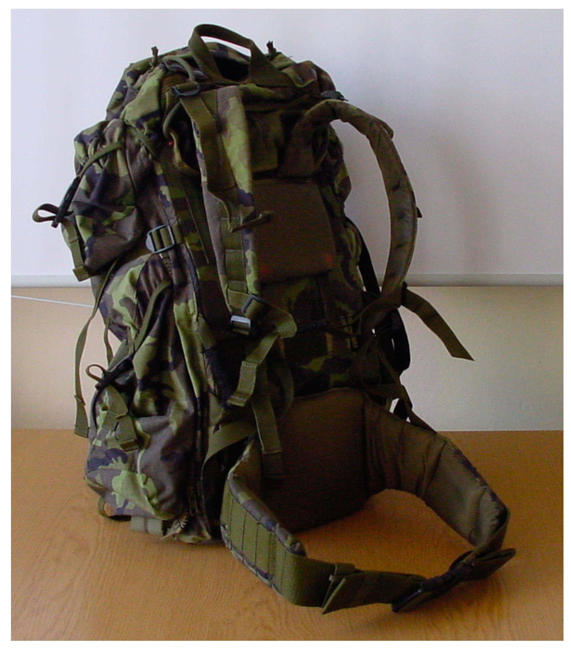
The personal airborne equipment backpack TL-98 has been designated for the transport of parachutists’ accoutrements and armaments during jumps from airplanes or helicopters (
Figure 1).
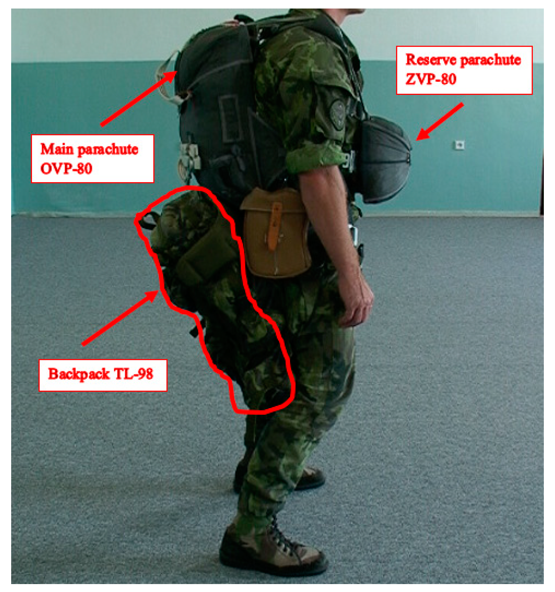
The backpack has been assigned for the transport of parachutists´ accoutrements and armaments after landing on ground or in water, and the backpack´s carrier unit was constructed for long-distance road marches as well. The backpack is anchored on the carrier unit of the parachutists’ equipment before a jump (
Figure 2).
During the jump phase, which starts with the jump from the aircraft and continues until the parachute’s opening (free-fall included), it is necessary for the anchoring to be trouble-free and reliable, specifically in terms of force effects retarding the parachute’s opening. After the parachute opening and during the flight and descending phase, a parachutist releases the anchoring system of the TL-98 backpack. Then the system performs a 4 m free-fall. The free-fall is pulled back by the rope and the backpack remains hanging under the parachutist (
Figure 3).
The main object of this study was the acquisition of information about the influence of the force effects of the discontinued fall of the TL-98 backpack on the objective rope. The defined goal was to determine the rope’s lifetime in parachutist operations. The maximum total weight of the personal airborne equipment backpack is 50 kg. The stopping of the force impact power, which is generated during the free-fall, must be reliably absorbed by the rope. In the context of this project, it was necessary to define the frequency of rope use which ensures the rope’s reliability and reasonably eliminates the rope’s malfunction or breakage during parachutist operations.
Several studies [
1,
2,
3,
4,
5,
6,
7] were devoted to the issue of rope testing, but they are applicable to mountaineering or to work done at heights using rope procedures. These studies provide procedures for testing ropes and the results of their testing. However, testing in this area is strictly regulated by standards, and in the European area these are, for example, the standards for static ropes (EN 1891) [
8], for dynamic ropes (EN 892) [
9] or for auxiliary ropes (EN 564) [
10]. Testing according to these standards can only be performed in laboratory conditions and cannot be applied during flight or parachuting operations. For these reasons, a procedure was developed for testing the rope in parachute operations during parachute flight, and this procedure was also applied in ground fall tests. This made it possible to compare the results from the fall tests obtained during the parachute flight with the results from the ground tests. The developed methodology used during the experiments is described in
Section 2.
Section 2 identifies the materials used in the experiments and describes the experimental methodologies.
Section 3 presents the results of the fall tests from ground testing and from the test jump. The theoretical calculation of the impact force during the fall tests is given in
Section 4, including a comparison of the calculated values with the values measured during the experiments. In the conclusion, there are predetermined rules for determining the lifetime of the rope and the results of that process.
2. Materials and Methods
The controlled criteria for functionality and reliability for the purpose of this project were defined as follows [
11]:
retain a failure-free fixing of the backpack onto the parachute equipment during dropping from the aircraft, the parachute opening, and flight itself;
failure-free disconnection of the backpack from the parachute equipment, stopping of backpack’s fall by the rope, and the process of the parachute flight with the backpack on the rope;
failure-free operation of the parachute equipment, the anchoring points of the backpack, and the rope by a visual check of the fall test.
General procedures for mountain-climbing rope fall tests were considered in developing the method for the TL-98 backpack free-fall tests as well as for ropes used as a personal protection tool for preventing falls in [
1,
2,
8,
9,
10]. However, these procedures had to be adapted to the test and to standard parachute operation as well to the test’s repeatability.
For the purpose of the fall tests, a 5 m long rope (of which 1 meter was used to tie the knots) with a 6 mm diameter and meeting EN 564 standards was used. The manufacturer guarantees the minimum tensile strength to be 7200 N. The type of rope for testing was designed by the backpack manufacturer, taking into account two basic rope requirements. The first was sufficient strength and the second was the smallest possible rope diameter to take up as little volume as possible after being placed in the backpack. Therefore, a rope meeting the EN 564 standard with a diameter of 6 mm was used in the tests. For example, dynamic ropes meeting the EN 892 standard would be more advantageous for the absorption of impact forces, but they are only produced with a larger diameter.
2.1. Rope-Fastening Procedure
During the flight tests the rope was fixed by a simple figure-eight loop on the backpack (
Figure 4). The anchoring of the rope onto parachute equipment OVP-80 was fixed by carabiners and a TSG-073 tensometric apparatus for strength scanning. In standard operations, the rope anchored to parachute equipment OVP-80 is achieved by routing the rope around the main ring strap with a simple figure-eight loop (
Figure 5 and
Figure 6). The final fixation of the rope was achieved with the carabiner, which was affixed with a few simple figure-eight loops tied on the rope (
Figure 7). The full procedure is illustrated in the
Figure 4,
Figure 5,
Figure 6 and
Figure 7. The procedure for anchoring the rope to the backpack during the ground tests was identical to the flight test procedures. The other part of the rope was anchored to the TSG-073 tensometric apparatus for strength scanning, and the tensometric apparatus was anchored to the steel-concrete balcony construction (defined as the fixed point for this project) with a carabiner [
12].
2.2. Tensometric Force Sensing Device
For the measurement of the force impact values for the rope during braking and the final stop of the free-fall of the backpack, a TSG-073 tensometric force sensing device (
Figure 8) with the following characteristics was used [
13]:
measuring range 0 N–50,000 N
overload capacity 150%
safety index 4
measuring accuracy 0.1%
number of measuring channels 1
sampling 0.1 s–20 s
memory maximum 25,000 values (25,000 measured force values)
2.3. Ground and Flight Test Methodology
Six flight tests for this project (delivery of a test dummy) were performed without the measurement of the force impact values. The backpack weight was 60 kg (the maximum operational backpack weight of 50 kg was multiplied by a safety coefficient of 1.2). The strength of the backpack’s anchorage points (by which the backpack is attached to the parachute harness) was verified in flight tests where it was dropped from the aircraft at the maximum operating speed and at the maximum operating weight of the backpack, which had been increased by a safety factor of 1.2. The tests of the backpack and rope functionality and reliability were performed according to the controlled criteria presented at the beginning of
Section 2 (applicable for all tests in this project).
Apart from the above mentioned flight tests, 4 other fall tests were executed for the measurement of the force impact values for the rope during braking and the final stopping of the backpack´s free-fall. The backpack weighed 28 kg and the test conditions were as follows:
three ground fall tests (fall tests numbers 1, 2, and 3) were conducted whereby a new rope was used in test number 1 and the very same rope was reused in tests 2 and 3. The knots on the rope were untied and re-tied after each test;
one parachutist jump test (
Figure 9 and
Figure 10) with parachute equipment OVP-80 (fall test number 4). A new rope was used for test number 4.
During ground fall tests and the test jump, a weight of 28 kg was used; the weight was limited by the maximum operating weight of the OVP-80 parachute for the jump, which is 140 kg (test parachutist 91 kg, main and reserve parachute 19 kg, backpack 28 kg, and force sensor 2 kg, totaling 140 kg). Therefore, due to our requirement to compare the results between the ground fall tests and the test jump, a backpack weight of 28 kg was chosen for all tests and this weight could not be exceeded.
During this test, a device was used to activate the release of the backpack from the parachute harness, which is primarily intended to verify the functionality of the opening of the parachute container [
14]. This device had to be slightly modified to perform this test. The test parachutist cut the cord blocking the 3-ring system (the system used in parachuting to attach and release the main parachute) by pulling the handle of this device. After unlocking the 3-ring system, the anchor strap was released and the backpack began to fall freely.
The measurement results of fall tests numbers 1, 2, 3, and 4 are recorded in
Section 3. These are the measurement results of the force impact values for the rope during braking and total stop of the backpack’s free-fall. The force impact values were recorded in the time range of 0.05 s. The length of the rope used was 5 m, whereby 4 m of the rope was used for braking and total stopping of the free-fall (1 m of the rope was used for the binding knots).
3. Results
3.1. Fall Tests for the TL-98: Ground Testing
3.1.1. Fall Test Number 1
The rope was anchored with carabiner to the TSG-073 tensometric force sensing device and the tensometric apparatus was anchored to the steel-concrete balcony construction (for this project defined as the fixed point) with a carabiner. During braking and the final stopping of the free-fall of the 28 kg backpack, the force impact values were recorded and are inscribed in
Table 1.
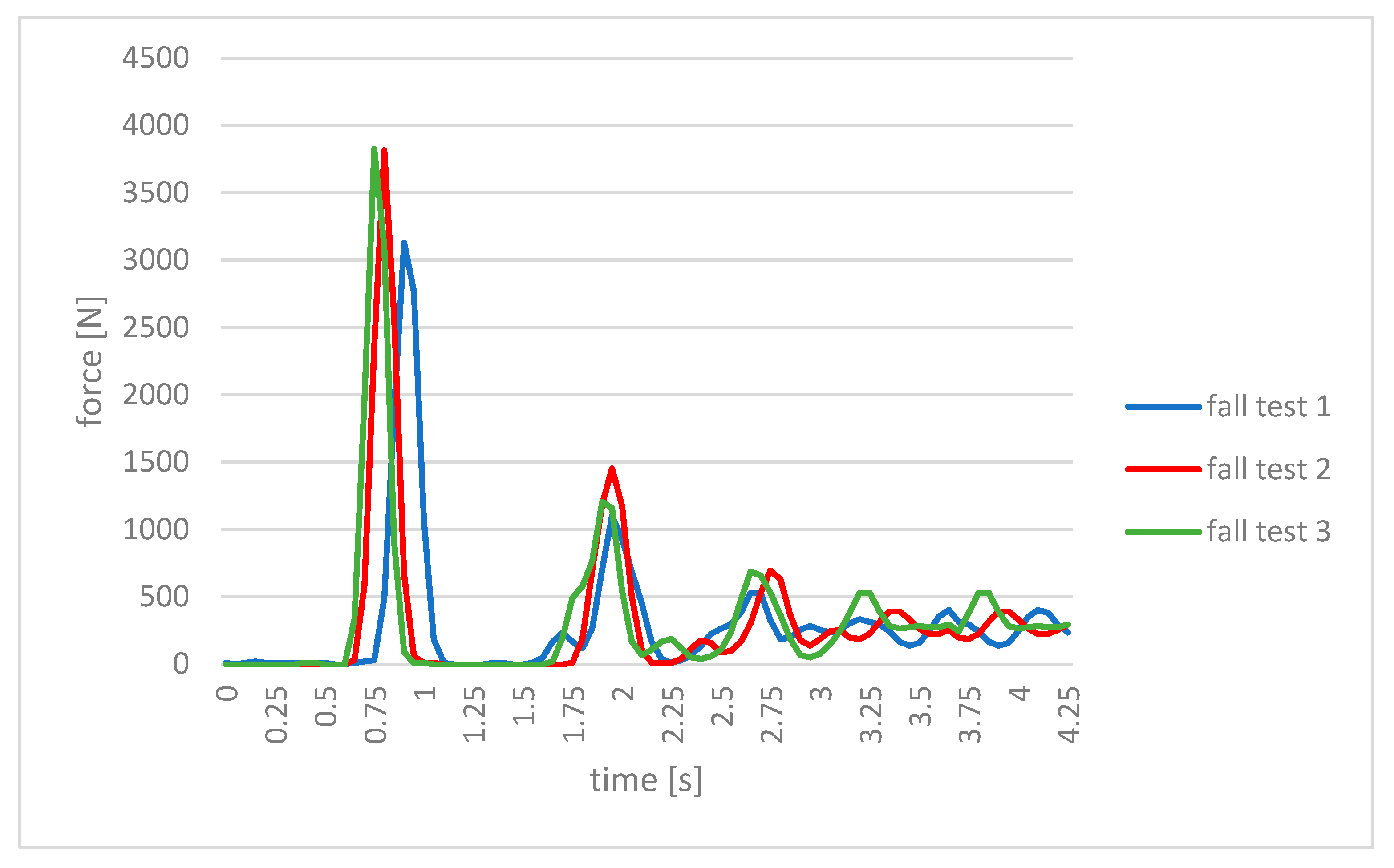
The fall stopped at 0.9 s, when the first maximum force impact value was recorded (3129 N). At this moment, the backpack was tossed upwards by the upward direction of the force of the rope’s elasticity and its second fall then started from a lower level at 1.5 s in the time sequence. This fall stopped at 1.95 s when the second maximum force impact value (1099 N) was recorded. The third maximum force value (530 N) was recorded at 2.65 s in the sequence. Consequently, the backpack still underwent several up and down movements until finally settling.
3.1.2. Fall Test Number 2
The fall stopped at 0.8 s when the first maximum force impact value (3816 N) was recorded. At this time, the backpack was tossed upwards by the upward direction of the force of the rope’s elasticity, and at 1.7 s in the time sequence, the backpack began its second fall from a lower height. This fall stopped at 1.95 s, when the second maximum force impact value (1452 N) was recorded. The third maximum force impact value (697 N) was recorded at 2.75 s in the time sequence. Consequently, the backpack still underwent several up and down movements until finally settling.
3.1.3. Fall Test Number 3
The fall stopped at 0.75 s when the first maximum force impact value (3626 N) was recorded. At this moment, the backpack was tossed upwards by the upward direction of the force of the rope’s elasticity, and at 1.6 s in the time sequence, the backpack began its second fall from a lower height. This fall stopped at 1.9 s, when the second maximum force impact value (1207 N) was recorded. The third maximum force impact value (687 N) was recorded at 2.65 s in the time sequence. Consequently, the backpack still underwent several up and down movements until finally settling. Comparison of force impact values is presented in
Figure 11.
3.2. Fall Tests for the TL-98:Flight Testing during the Jump of the Test Skydiver
The rope was anchored to the polyamide strap of the carrier equipment of parachute set OVP-80. The backpack was released during the descending parachute phase at a vertical speed of approximately 5 m·s
−1. During the braking and final stop of the 28 kg backpack’s free-fall, force impact values were recorded and are inscribed in
Table 2.
The fall stopped at 0.85 s when the first maximum force impact value (2080 N) was recorded. At this time, the backpack was tossed upwards by the upward direction of the force of the rope’s elasticity, and at 1.75 s in the time sequence, the backpack began its second fall from a lower height. This fall stopped at 1.75 s, when the second maximum force impact value (647 N) was recorded. The third maximum force impact value (618 N) was recorded at 2.75 s in the time sequence. Consequently, the backpack still underwent several up and down movements until finally settling.
4. Discussion
The force impact value after the discontinuance of the backpack’s free-fall depends on the kinetic energy mass which the backpack is losing and the trajectory from which the loss originates. The force impact value after the discontinuance of the free-fall can be defined as [
15]:
where:
F—force impact [N]
Ek—kinetic energy [J]
s—trajectory, on which the retardation of the backpack originates and achieves zero speed [m]
v—speed at a time of the retardation starts [m·s−1]
m—backpack weight [kg] m = 28 kg
The free-fall speed of the backpack at the moment when the stretched rope turns and starts to retard the backpack can be calculated by a function (valid for the cases with no air resistance, which could be neglected with regard to a 4 m free-fall height):
where:
If
t0 = 0 then
t =
t1 and the free-fall speed of the backpack at the moment when the rope gets stretched and begins to retard the backpack, then we can calculate by a familiar function (valid for cases with no air resistance, which could be neglected with regard to a 4 m free-fall height):
The free-fall period of the backpack anchored by a 4 m rope was experimentally discovered during the fall tests and its value is 0.65 s. The trajectory on which the retardation of the backpack starts and achieves zero-value speed was determined by following the rope producer’s declaration of a maximum extension of up to 5%. Since the free-fall of the backpack can be discontinued by the 4 m long rope, then the retardation starts from the 0.2 m section. (This is relevant for fall tests numbers 1, 2, and 3, which were performed from a fixed point). In the case of free-fall test number 4, a part of the kinetic energy was absorbed by the polyamide strap of the carrying gear of the parachute set OVP-80. Thus, based on an expert predetermination, we can estimate that the retardation started at the 0.3 m section. Based upon the presented relations and assumptions, the value of the calculated force impact during the fall tests of the backpack from the fixed point
F1 (retardation on the 0.2 m section) is:
The value of the calculated force impact during the fall tests of the backpack from the flexible point (retardation on the 0.3 m section):
Maximal force impact values, measured at the time of the fall in test numbers 1, 2, and 3 (average value 3590 N) are similar to the calculated force impact value of F1 = 2846 N. Moreover, the maximum force impact value measured during fall test number 4 (2080 N) is similar to the calculated force impact value F2 = 1879 N. The values measured in this way can be considered correct with the accepted simplification that the length of the rope and its calculated elongation were used in the calculations. It would be more accurate to use a center-of-gravity shift in the calculations. However, measuring the shift in center of gravity in fall tests (especially flight tests) is difficult to implement. Therefore, the calculations were performed with the accepted simplification. This argument makes provision for the fact that the calculation of the force impact is significantly influenced by the length of the section on which the retardation is performed. Additionally, as ascertained above, the lengths of the sections were determined as approximations only. Determination of the force impact value by the calculation must be compared with the experimentally measured result because the length of the section on which the retardation occurs has a significant influence on the calculation results. For a sufficient dimensioning of the rope in terms of parachutist operational safety, it is imperative to make provision for experimentally achieved force impact values.
Upon comparison of fall test numbers 1, 2, and 3, which were performed from a fixed point with the same rope used, the test results can be explained as follows. By increasing the number of falls, the rope loses its capacity to absorb the fall power and the force impact values gradually increase. The above mentioned reduction in the rope’s dynamic effects by the cumulative number of falls has been documented in [
3,
4,
5] too.
The three highest maximal force impact values achieved during fall test numbers 1, 2, and 3 are recorded in
Table 3. Recorded numerical values clarify the increase in the force impact values by the increasing number of falls. Even though the rope was anchored to the fixed point (in significantly adverse conditions in comparison with the flexible point of live parachutist operations), the producer’s guaranteed minimum tensile strength was not exceeded anyway. The minimum tensile strength was defined as 7200 N. The presented values in the first maximum force impact values did not exceed even half of the producer´s guaranteed tensile strength [
11].
Comparison of the force impact values during fall test numbers 1 and 4 are shown in
Figure 12.
A new rope was used for both tests. This comparison illustrates the ability of the fall power to be absorbed by the rope fixed to the steel-concrete balcony construction (defined as the fixed point for this project) in comparison with its installation into the polyamide strap of the carrying gear construction of parachute set OVP-80 (the flexible system). These tests confirmed the prediction that the absorption of the fall energy by the rope anchored to the elastic system of the parachute gear on a human body (compared with fixing it to a fixed inelastic point) are be more effective, and the force impact values achieve lower figures in this case. In numerical terms, there was a decrease in the maximal force impact value by approximately 30%. A favorable influence on the reported matter has been affirmed by the fact that the backpack fall is retarded and stopped by the rope installed onto the parachute set, which descends by a vertical speed of approximately 5 m·s
−1 [
11].
5. Conclusions
The ground and flight tests of the backpack TL-98 confirmed its functionality and reliability according to the definitions mentioned in
Section 2. In terms of safety, the trouble-free backpack fixation on the parachutist’s gear during dropping from an aircraft, parachute opening, and parachute flight itself were affirmed. The trouble-free backpack release off of the parachute gear, the stopping of the backpack’s free-fall by the rope, and parachute operation with the backpack hung on the rope were also confirmed.
For reasons of defining the rope’s operational life, one that retards and stops the backpack TL-98’s fall, the below mentioned principles were defined:
the measured force impact values for the rope must not exceed 50%, even in a single case, of the values of the tensile strength guaranteed by the producer;
all the fall tests must preserve functionality and reliability (in terms of the definition presented in
Section 2);
in the case when two of the above mentioned conditions have been met, then the rope’s lifetime for live parachutist operation can be defined in the form of the maximal number of rope disposals (the maximal number times retarding and stopping TL-98 backpack free-falls) and as follows: the number of flight tests (the test dummy deliveries) without a measurement of the force impact values of a 60 kg backpack (the 50 kg backpack´s maximal operational weight multiplied by the safety quotient of 1.2) while preserving functionality and reliability according to the controlled characteristics multiplied by 10.
Six flight tests were performed in the range of this project and resulted in the conclusion that serviceable use of the rope in live parachute operation can be assigned for up to 60 applications [
11].
The tasks included in [
6,
7,
16] became basics for elaborating the procedures to define the retarding and stopping in the TL-98 backpack rope’s lifetime. The operational life of a rope is generally considered as an abstract question. It is difficult to define a rope’s exact operational life. Ropes with a lifetime of 10 years are also currently available. However, in the case of free-fall capture with a higher value of the fall factor, manufacturers generally do not recommend further use. The value of this fall factor varies from manufacturer to manufacturer and ranges from approximately 0.5 to 1.5. Of course, it is also important whether the rope was stressed over a sharp edge. Rope lifetime can be specified only approximately. It depends on many factors, such as the forms of utilization, rope type, care of the rope, its storage, climate conditions, etc. The number of successful fall retardations and stops, rope use, and age can all degrade a rope’s ability to retard and stop a fall [
6].
Author Contributions
Conceptualization, P.K., R.R., A.T. and M.A.; methodology, P.K.; software P.K. and R.R.; validation, P.K., R.R. and A.T.; formal analysis, A.T.; investigation, R.R. and M.A.; resources, M.A.; data curation, P.K. and A.T.; writing—original draft preparation, P.K. and R.R.; writing—review and editing, A.T. and M.A.; visualization, P.K.; supervision, R.R.; project administration, A.T.; funding acquisition, M.A. All authors have read and agreed to the published version of the manuscript.
Funding
This research received no external funding.
Institutional Review Board Statement
Not applicable.
Informed Consent Statement
Not applicable.
Data Availability Statement
Not applicable.
Conflicts of Interest
The authors declare no conflict of interest.
References
- Jasko, P. Testing Climbing Material According to UIAA and EN Standards; James: Liptovsky Mikulas, Slovakia, 2015; Available online: http://www.james.sk/file/metodika/UIAA_testy.pdf (accessed on 14 September 2021).
- UIAA. 101 Mountaineering and Climbing Equipment ‘DYNAMIC ROPES’; UIAA: Bern, Switzerland, 2016; Available online: http://theuiaa.org/documents/safety-standards/UIAA_101_7_ropes_may_2016.pdf (accessed on 21 October 2021).
- Methodological and Safety Commission SHS JAMES: Ropes I. 2012. Available online: http://www.james.sk/file/metodika/lana1.pdf (accessed on 21 October 2021).
- Weber, C. Fall Factors & Life Safety Ropes—A Closer Look; International Technical Rescue Symposium, Pigeon Mountain Industries, Inc.: LaFayette, GA, USA, 2001. Available online: http://caves.org/section/vertical/nh/47/itrs.pdf. (accessed on 2 November 2021).
- Weber, C.; Hudson, S. UIAA Dynamic Rope Drop Testing Results with Loads Greater than 80 kg; International Technical Rescue Symposium: Fort Collins, CO, USA, 1999. Available online: http://itrsonline.org/wordpress/wp-content/uploads/2014/09/Weber-Hudson1999_ITRSPaper.pdf (accessed on 2 November 2021).
- Methodological and Safety Commission SHS JAMES: Ropes II. 2012. Available online: http://www.james.sk/file/metodika/lana2.pdf (accessed on 2 November 2021).
- Mehew, B. Rope Testing—Some Thoughts: British Caving Association. Available online: http://british-caving.org.uk/wiki3/lib/exe/fetch.php?media=equipment_techniques:rope_testing_v1_a.pdf (accessed on 2 November 2021).
- STN EN 1891; Personal Protective Equipment for the Prevention of Falls from a Height. Low Stretch Kernmantel Ropes. UNMS SR: Bratislava, Slovakia, 2001.
- STN EN 892+A1; Mountaineering Equipment. Dynamic Mountaineering Ropes. Safety Requirements and Test Methods. UNMS SR: Bratislava, Slovakia, 2017.
- STN EN 564; Mountaineering Equipment. Accessory Cord. Safety Requirements and Test Methods. UNMS SR: Bratislava, Slovakia, 2007.
- Kalavsky, P. Program and Test Methodology and the Final Report from the Project Airborne Use of the TL-98 Backpack in Armed Forces of the Slovak Republic; Slovak Aeronautical Institute JSC: Kosice, Slovakia, 2005. [Google Scholar]
- Kalavsky, P. Methodology of Airborne Use of TL-98 Backpack in Armed Forces of the Slovak Republic; Slovak Aeronautical Institute JSC: Kosice, Slovakia, 2005. [Google Scholar]
- Letko, R. User Manual for the Tensometric Force Sensing Device TSG-073; MDV: Bratislava, Slovakia, 2005. [Google Scholar]
- Kalavsky, P.; Kelemen, M.; Rozeneberg, R.A.; Antosko, M. Functionality Verification Device for the Opening of the Parachute Container at the Bottom of the Container; Utility Model No. 9226; Industrial Property Office of the Slovak Republic: Banska Bystrica, Slovakia, 2020. Available online: https://wbr.indprop.gov.sk/WebRegistre/UzitkovyVzor/Detail/50028-2020 (accessed on 2 March 2022).
- Cejpa, C. Textbooks for Parachuting. Theory and Practice of Parachute Sport; Our Troops: Prague, Czech Republic, 1961. [Google Scholar]
- Kelemen, M.; Polishchuk, V.; Gavurová, B.; Andoga, R.; Szabo, S.; Yang, W.; Christodoulakis, J.; Gera, M.; Kozuba, J.; Kaľavský, P.; et al. Educational Model for Evaluation of Airport NIS Security for Safe and Sustainable Air Transport. Sustainability 2020, 12, 6352. [Google Scholar] [CrossRef]
| Publisher’s Note: MDPI stays neutral with regard to jurisdictional claims in published maps and institutional affiliations. |
© 2022 by the authors. Licensee MDPI, Basel, Switzerland. This article is an open access article distributed under the terms and conditions of the Creative Commons Attribution (CC BY) license (https://creativecommons.org/licenses/by/4.0/).


