Article

Asymmetric Encryption of Invisible Structured Light 3D Imaging

1
College of Mathematics and Science, Shanghai Normal University, Shanghai 200234, China
2
Department of Engineering Technology, Middle Tennessee State University, Murfreesboro, TN 37132, USA
*
Author to whom correspondence should be addressed.
Appl. Sci. 2022, 12(7), 3563; https://doi.org/10.3390/app12073563
Submission received: 23 February 2022 / Revised: 26 March 2022 / Accepted: 29 March 2022 / Published: 31 March 2022
(This article belongs to the Topic Optical and Optoelectronic Materials and Applications)

Abstract

:
The research proposes a novel invisible structured light 3D object encryption method. The system projects invisible light on the target plane to achieve three-dimensional object reconstruction. The encryption is conducted using keys from eight stripe patterns and two fingerprint patterns using an elliptic curve encryption algorithm to generate eight corresponding ciphertexts. The three-dimensional object is reconstructed using eight fringe patterns with the elliptic curve decryption algorithm. The proposed method greatly reduces the interference of background light in the system to achieve a better 3D imaging accuracy. The elliptic curve cryptosystem is able to ensure 3D object information transmission security. The simulation results validated the robustness and effectiveness of the proposed scheme. The proposed method has practical security-sensitive applications.

Graphical Abstract

1. Introduction

Structured light 3D imaging technology has been studied since the 1950s [1,2,3,4,5]. Srinivasan et al. proposed phase measurement profilometry to obtain phase information by projecting grating patterns with certain phase differences onto an object [6]. Following decades of continuous development, a variety of structured light 3D imaging technologies have emerged. Structured light 3D imaging technology consists of the point structured light, line structured light method [7,8,9], and surface structured light method [10]. Among them, the surface structured light method is used more often and is therefore discussed.
Zeng et al. proposed an improved stepped phase coded fringe and a new phase unwrapping algorithm based on the order of the shifted fringe [11]. The main idea of this method is to set the width ratio between each step phase of the sinusoidal fringe and phase coded fringe to 1:n. The fringe order retrieved from the phase coded fringe can be multiplied by the offset itself to assist the phase unwrapping process. This method can ensure high measurement accuracy and allow the measurement of isolated objects with complex shapes. Takeda et al. proposed a new technology, Fourier transform profilometry (FTP), which is suitable for automatic measurement of three-dimensional object shapes [12]. Because FTP does not use moire contour technology, it does not have the drawbacks related to moire terrain. The advantage of FTP is that it can detect the height changes more accurately than moire contour technology, and it is completely free of the unwanted stray moire fringes generated by the high-order harmonic component of the grating pattern. Qian proposed the windowed Fourier transform to measure the phase and phase derivative using the two-dimensional windowed Fourier transform, which can perform better fringe demodulation and fringe pattern filtering [13,14].
Among other studies, Zhang et al. proposed a 3D reconstruction model based on the parallel axis structured light system [15]. Compared with the traditional structured light system, the new system includes a perspective projection unit and a telecentric imaging unit that can recover the height distribution of the object well with high accuracy. Yan et al. proposed a three-dimensional vision system combining structured light and the shadow shape [16]. This method is suitable for objects that have high motion frequencies. For this technique, the projected structured light vision system uses sinusoidal fringe coding to extract the shape from the shadow, which is can obtain the high-definition gradient information of the weak fluctuation of the weld surface. it is worth noting that phase-shifting is a cost-effective method because of its simple equipment and high measurement accuracy. Mao et al. used this method of combining invisible structured light and phase-shifting 3D imaging technology, where two orthogonal polarized beams were projected onto the object surface without interference fringes [17]. The synchronous phase shift detection technology was then used to detect the structured light fringes to obtain the shape information of a three-dimensional object. The results showed that this method can effectively suppress the background light and greatly reduce the measurement error.
Various image encryption methods have been developed based on the classical Fourier transform [18]. In the public-private key cryptosystem, each user has a pair of keys: one is published publicly (public key) and the other is stored in a secure location (private key) [19,20,21]. Yuan et al. proposed a method of transmitting the double random phase encryption key and encrypted image at the same time [22]. This method takes advantage of the fact that only part of the encrypted image can obtain acceptable decryption results in the decryption process with an appropriate encryption strength. In this method, the double random phase encryption key is encoded into the encoding key through the Rivest–Shamir–Adelman (RSA) public key encryption algorithm, which is subsequently used to modulate the amplitude of the image for encryption. Meng et al. proposed a hybrid cryptosystem, combining double random phase coding (DRPE) and two-step phase-shifting interferometry (2-PSI) for the encryption of an image into two interferograms, and then used three pairs of public and private keys to encode and decode the session key (geometric parameters, the second random phase mask) and the interferogram [23]. On the other spectrum of encryption, Bi et al. proposed a social network privacy data aggregation encryption method based on matrix decomposition [24]. With this method, the Shamir threshold segmentation scheme is adopted to improve the security of matrix decomposition followed by network user attributes encryption. Similarly, Wang et al. proposed a learning-based reversible encryption network (IENet) for optical image encryption [25]. The method uses IENET for the encryption of the pure phase hologram, which has a large number of key parameters and strong key sensitivity. Compared with the RSA algorithm, the elliptic curve cryptography (ECC) algorithm proposed by Miller [26] and Koblitz [27] requires a smaller number of parameters with a similar security strength [21,22]. Specifically, the ECC algorithm with a 600 bit key has the same security level as the 21,000 bit RSA system [21]. Therefore, elliptic curve cryptography is attractive in mobile computing because of its small key. While lightweight in computation, it has been proved that it will take an attacker a significant amount of time to solve the elliptic curve discrete logarithm problem. Because of these advantages, it is not surprising that researchers have used elliptic curve cryptography in optical encryption systems [28,29,30].
An evident gap exists regarding the encryption of three-dimensional data. Efforts have been made toward this. Yan et al. proposed a three-dimensional object image encryption system based on the optical heterodyne technology and biological fingerprint key. Using this method, the three-dimensional multi depth object image can be encrypted into a complex encrypted hologram. Then, by associating the encrypted hologram with a set of pinhole holograms, the three-dimensional object image is recovered from the encrypted hologram. The limitation of the method is that the encrypted data is pseudo three-dimensional with different sections. For the encryption of three-dimensional data, structured light projection is an option for realizing the encrypted transmission of real three-dimensional objects [31].
This paper proposes a new imaging method based on the combination of invisible structured light 3D imaging technology and elliptic curve cryptography. This innovative method relies on elliptic curve encryption to ensure the security of three-dimensional object information transmission. This method can effectively suppress the interference from background light by introducing invisible structured light. In the proposed scheme, an invisible structured light is projected on the target plane and three-dimensional object to generate eight fringe patterns. The eight fringe patterns and two random pattern keys are used as the input of the elliptic curve encryption system, which generates eight corresponding ciphertexts. The encryption keys are two random images. The advantage of using elliptic curve cryptography is that it is asymmetric, so the security of the encryption scheme is higher than that of the symmetric encryption scheme. Compared with the traditional structured light 3D imaging system, our imaging system has the following advantages. First, the combination of cryptography and optics provides a new insight for the application of laser 3D imaging technology in information security systems. Second, elliptic curve encryption is a typical asymmetric encryption algorithm, which greatly improve the security of object encryption, especially the key distribution problem in general optical encryption. Third, the error of the system is greatly reduced due to the introduction of invisible structure light as the projection light. In addition, the device of the system is relatively simple, and automation is easy. The encryption system has significant fault tolerance, which can effectively resist noise attacks. Overall, the method proposed in this paper provides a more secure and reliable solution for the transmission of 3D information.
The paper is organized as follows. The second section introduces the invisible structured light 3D imaging system. In the third section, the methods and simulation results are discussed. It shows the security and anti-noise ability of the encryption scheme. The fourth section summarizes the results of this paper.

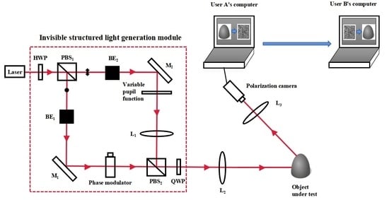
2. Invisible Structured Light 3D Imaging System

In the structured light 3D imaging method, the fast phase-shifting fringes are projected onto the target plane and measured successively to reconstruct the surface of three-dimensional objects. However, this method has one drawback that the eight interference fringes with phase shift obtained by bright fringe projection are easily affected by vibration and dynamic background light. Therefore, this paper adopts a projection scheme of invisible structured light fringe based on orthogonal polarization. The specific process is shown in Figure 1.

2.1. Obtaining the Eight Images for Encryption

The structured light imaging is detailed as shown in Figure 1. After passing through a half wave plate (HWP), the laser beam is divided into two beams in an orthogonal polarization state by a polarization beam splitter (PBS1), namely, horizontally polarized light and vertically polarized light. The horizontally polarized light is expanded by the beam expander (BE2) and the reflector (M2), passes through a variable pupil that is adopted to adjust the size of the light, and irradiates on the polarizing beam combiner (PBS2) through the lens (L1). At the same time, the vertically polarized light is expanded by the beam expander (BE1) and the reflector (M1), and then irradiates on the polarization beam combiner after passing through the phase modulator, which is applied to control the phase. Vertically polarized light and horizontally polarized light pass through a quarter wave plate (QWP) and finally form an invisible structure light with an orthogonal polarization direction and controllable phase and size. It is then transmitted to the object under test by the lens (L2). Because the two beams are orthogonal polarization states, the interference structure light pattern cannot be seen on the target plane, and can only be detected at the receiving end, so it is called “invisible structure light”.
Using the invisible structure light-emitting system, after emitting 2 orthogonal polarized lights to irradiate the target plane, the expressions of 4 sinusoidal fringes with phase shifts of 0, π/2, π, and 3π/2 can be obtained using a convergent lens (L3) and polarization camera, which can be expressed as:
I 0 ( x , y ) = a 0 2 z 2 [ 1 + sin ( k x d M z + k d 2 2 z ) ]
I π 2 ( x , y ) = a 0 2 z 2 [ 1 + cos ( k x d M z + k d 2 2 z ) ]
I π ( x , y ) = a 0 2 z 2 [ 1 sin ( k x d M z + k d 2 2 z ) ]
I 3 π 2 ( x , y ) = a 0 2 z 2 [ 1 cos ( k x d M z + k d 2 2 z ) ]
where a0 represents the amplitude at a unit distance from the point light source, z represents the distance between the L2 focus position and target plane, k represents the wave number, d represents the distance of the convergence point of two orthogonal polarized lights after passing through the lens L2, and M represents the imaging magnification of the camera.

2.2. Encryption Using the Elliptic Curve Encryption Algorithm

To obtain the phase value of the object, eight fringe images are obtained by irradiating the target plane and the measured object, respectively, with structured light. Following the collections of eight images, the elliptic curve encryption algorithm is used to encrypt the eight images. The eight fringe images generated by the measurement system are used as the plaintext m of the elliptic curve encryption algorithm. Among them, elliptic curve encryption is a key agreement algorithm based on the elliptic curve arithmetic rule of modulo p over a finite field. With the algorithm, the information of the elliptic curve parameters (p, a, b, G, n) is open to users A and B. The elliptic curve equation determined by a and b is y2 = x3 + ax + b, G is the generator of elliptic curve, and n is the order of G. In the simulation experiment, the parameters p, a, b, and G are set to 10,007, 1, 1, and (2, 2), respectively. Then, user A selects ka as its private key and Pa as his public key, where ka is an integer matrix less than n and Pa is the result of ka × G. User B selects kb as the private key, and Pb as the public key, where kb is an integer matrix less than n, and Pb is the result of kb × G. When user A transmits plaintext m to user B, KA is used to calculate the plaintext m to obtain the encrypted ciphertext c, which is then transmitted to user B, where the encryption key KA is the result of ka × Pb and c is the result of m + KA. The elliptic curve encryption flow chart is shown in Figure 2.

2.3. Decryption Using the Elliptic Curve Encryption Algorithm

After receiving the ciphertext map, the receiver uses the elliptic curve decryption algorithm to decrypt the measured object. After receiving the encrypted ciphertext c, user B calculates KB and then calculates the plaintext m to obtain the decrypted images. Decryption key KB is the result of kb × Pa and m is the result of c−KB, and finally the decrypted images can be obtained. The elliptic curve decryption flow chart is shown in Figure 3.

2.4. Reconstruction of the Three-Dimensional Image of the Measured Object

According to the light intensity distribution of the four-step phase-shifted sinusoidal fringes at each different position, the actual phase value at this position is:
ϕ ( x , y ) = arctan [ I 0 ( x , y ) I π ( x , y ) I π 2 ( x , y ) I 3 π 2 ( x , y ) ]
The phase function φ(x,y) after decryption of the measured object is the three-dimensional shape of the object h(x, y):
h ( x , y ) = L T Δ ϕ 2 π b + T Δ ϕ
where L represents the distance between the target and the imaging camera, T represents the period of the projected fringe, Δ ϕ ( x , y ) represents the phase of the measured object minus the phase value of the target plane, and b represents the distance between the receiving camera and the transmitting center. In this way, the height information of the object can be obtained by extracting the phase of the deformed fringe. In the simulation experiment, the parameters L, T, and b are set to 660, 51 / 2 , and 155, respectively.

3. Simulation Results and Performance Analyses

3.1. Encryption Result Analysis

During encryption, the 8 fringe images are shown in Figure 4a–h, the 4 fringe images generated by the target plane are shown in Figure 4a–d, and the 4 deformed fringe images generated by the measured object are shown in Figure 4e–h. The private key ka of user A is shown in Figure 5a, and the public key Pa is shown in Figure 5b,c. The private key kb of user B is shown in Figure 5d, and the public key Pb is shown in Figure 5e–f. The encrypted ciphertext images are shown in Figure 6a–h. The decrypted images are shown in Figure 7a–h.

3.2. Analysis of Imaging Results

Using the method proposed in this paper, the results of the three-dimensional reconstruction are shown in the figure below. Figure 8a shows the measured three-dimensional object. Figure 8b shows a three-dimensional object after decryption recovery. Through the comparison of the two images, the system can effectively restore the measured three-dimensional object.

3.3. Histogram Analysis

The histogram is used to judge the security of image encryption by analyzing the number of occurrences of each gray level in the image. The more uniform the distribution of the gray histogram and with no obvious features, the more resistant it is to the attack of statistical analysis. The following figure shows the histogram of the original image and ciphertext image. Figure 9a–h show the histograms of the eight original images. Figure 10a–h show the histograms of the eight ciphertext images. Obviously, the ciphertext images are evenly distributed and have no obvious features. Therefore, ciphertext can effectively resist statistical analysis attacks.

3.4. Adjacent Pixel Correlation

The correlation of adjacent pixels is used to represent the correlation degree of pixel values in adjacent positions of an image. The purpose of using the image encryption algorithm for the original image is to reduce the correlation of adjacent pixels as much as possible, which includes the correlation among horizontal pixels, vertical pixels, and diagonal pixels. The smaller the correlation is, the better the encryption strength, yielding higher security. This paper analyzes the correlation between adjacent pixels from three directions: horizontal, vertical, and diagonal, for the eight original images and eight ciphertext images. Among them, Figure 11 shows the adjacent pixel distribution of the 8 original images, from which we can observe the clear association pattern of the original image. Figure 12 shows the adjacent pixel distribution of the 8 ciphertext images. It is evident that the pixel distribution in the encrypted image is uniform. Table 1 shows the correlation coefficients of the 8 original images and Table 2 shows the correlation coefficients of the 8 ciphertext images in 3 directions. For the eight original non-encrypted images, the correlation of adjacent pixels in the three directions is high. In contrast, for the 8 ciphertext images, the correlation of adjacent pixels in the 3 directions is very small, close to 0.

3.5. Information Entropy Analysis

In information theory, information entropy refers to the average amount of information contained in each received message, which is a measure of uncertainty. The calculation formula is as follows:
H ( m ) = j = 0 255 p ( m j ) log 2 p ( m j )
where p(mj) is the probability of information. A grayscale image has 28 grayscale values. Assuming that each gray value has the same probability, according to Equation (7) H(m), to ensure the security of the original image, the information entropy of the ciphertext image should be close to 8. Table 3 shows the information entropy of the 8 original images and 8 ciphertext images. From the data in the table, we can see that the information entropy of the encrypted image is closer to 8 than that of the original image, which indicates that the use of the encryption algorithm improves the complexity of the ciphertext, thus resulting in stronger security.

3.6. Noise Attack Analysis

In the process of image transmission, the ciphertext image may be injected with noise by hackers. Therefore, salt and pepper noise with 0.1 density is introduced to detect the anti-noise ability of the system. Salt and pepper noise, also known as impulse noise, is the noise often seen in images. It is a kind of random white or black dot. Figure 13a–h shows the ciphertext after introducing noise. Then, the original 8 fringe images are median filtered, as shown in Figure 14a–h. The images after filtering are shown in Figure 14i–p. The measured object is reconstructed, as shown in Figure 15. Obviously, the original 3D object can still be reconstructed even when noise exists. The results show that the imaging system has high anti-noise ability. Next, we use structural similarity (SSIM) to detect the anti-noise ability of the eight images under different salt and pepper noise densities. Among them, SSIM is an index used to measure the similarity of two images. The specific expression of SSIM is as follows:
S S I M = ( 2 μ x μ y + Q 1 μ x 2 + μ y 2 + Q 1 ) ( 2 σ x σ y + Q 2 σ x 2 + σ y 2 + Q 2 ) ( σ x y + Q 3 σ x σ y + Q 3 )
where μ x and μ x are the average values of the original pattern and the decrypted pattern, respectively; σ x and σ y are the variance of the original pattern and the decrypted pattern, respectively; σ x y is the covariance between the original pattern and the decrypted pattern; and Q 1 , Q 2 , and Q 3 are constants. The value of SSIM is a value from 0 to 1. The closer the value is to 1, the smaller the gap between the original pattern and the decrypted pattern, thus the image reconstruction quality is enhanced. SSIM of the 8 images under different salt and pepper noise densities is shown in Table 4. It can be concluded from the data in the table that the eight images have a strong anti-noise ability when different salt and pepper noises are introduced.

3.7. Known Plaintext Attack

To further verify the security of the cryptosystem, the known plaintext attack is carried out on the system. As shown in Figure 5e,f the cryptosystem’s ability to resist a known plaintext attack is determined. If the public and fixed P b is used, it will be vulnerable to a known plaintext attack, but changing the value of P b frequently will make our cryptosystem more complicated. To solve this problem, user B can randomly generate a secret key k s and transmit k s × G , P b + k s × P a to user A, as shown in Figure 16. Then, user A calculates the following equation:
P b + k s × P a k a × k s × G = P b
where P a = k a × G . Therefore, P b will be hidden and our cryptosystem can resist a known plaintext attack.

4. Conclusions

In this research, we propose a new imaging method based on the combination of invisible structured light 3D imaging technology and elliptic curve cryptography. The proposed scheme has the following advantages: first, it combines cryptography and optics, constructs a scheme that combines digital encryption and 3D imaging, and provides a new method for the safe transmission of 3D object information. Second, using elliptic curve cryptography, a typical asymmetric encryption algorithm, to encrypt and decrypt eight images generated by four-step phase shift was shown to greatly improve the security of object encryption. Moreover, the elliptic curve cryptography algorithm solves the challenging key distribution problem to achieve asymmetric encryption. Third, with invisible structured light as the projection light, the adverse impact of the background light is suppressed, thus significantly reducing the system error. Fourth, the device of the system is simple, and automation is easy. The encryption system has a large fault tolerance, which can effectively resist a noise attack and known plaintext attack. Last, the encryption strength was proven using the image histogram, the correlation of adjacent pixels, correlation coefficient of adjacent pixels, structural similarity, and information entropy. It showed that the system is robust to noise attacks, and can effectively restore the 3D information of the original object. It is expected that the proposed solution will have practical secure 3D imaging applications.

Author Contributions

Conceptualization and methodology, A.Y. and J.Z.; writing—original draft preparation, J.Z.; reviewing and editing, H.Z. All authors have read and agreed to the published version of the manuscript.

Funding

This research was funded by the National Nature Science Foundation of China under grant, grant number 62075134.

Institutional Review Board Statement

Not applicable.

Informed Consent Statement

Not applicable.

Data Availability Statement

Not applicable.

Conflicts of Interest

The authors declare no conflict of interest.

References

  1. Xu, J.; Zhang, S. Status, challenges, and future perspectives of fringe projection profilometry. Opt. Lasers Eng. 2020, 135, 106193. [Google Scholar] [CrossRef]
  2. Cai, Z.; Liu, X.; Peng, X.; Yin, Y.; Li, A.; Wu, J.; Gao, B.Z. Structured light field 3D imaging. Opt. Express 2016, 24, 20324–20334. [Google Scholar] [CrossRef] [PubMed]
  3. Sam, V.; Dirckx, J. Real-time structured light profilometry: A review. Opt. Laser Eng. 2016, 87, 18–31. [Google Scholar]
  4. Feng, S.; Zhang, L.; Zuo, C.; Tao, T.; Chen, Q.; Gu, G. High dynamic range 3D measurements with fringe projection profilometry: A review. Meas. Sci. Technol. 2018, 29, 122001. [Google Scholar] [CrossRef]
  5. Yang, S.C.; Wu, G.X.; Yan, J.; Luo, H.F.; Zhang, Y.N.; Liu, F. High-accuracy high-speed unconstrained fringe projection pro-filometry of 3D measurement. Opt. Laser Technol. 2020, 125, 106063. [Google Scholar] [CrossRef]
  6. Srinivasan, V.; Liu, H.C.; Halioua, M. Automated phase-measuring profilometry of 3-D diffuse objects. Appl. Opt. 1984, 23, 3105–3108. [Google Scholar] [CrossRef] [PubMed]
  7. Cao, X.; Xie, W.; Ahmed, S.M.; Li, C.R. Defect detection method for rail surface based on line-structured light. Measurement 2020, 159, 107771. [Google Scholar] [CrossRef]
  8. Guo, X.Z.; Shi, Z.Y.; Yu, B.; Zhao, B.Y.; Li, K.; Sun, Y.Q. 3D measurement of gears based on a line structured light sensor. Precis. Eng. 2020, 61, 160–169. [Google Scholar] [CrossRef]
  9. Pan, X.; Liu, Z. High-accuracy calibration of line-structured light vision sensor by correction of image deviation. Opt. Express 2019, 27, 4364–4385. [Google Scholar] [CrossRef]
  10. Jae-Sang, H.; George, T.; Song, Z. High-speed and high-accuracy 3D surface measurement using a mechanical projector. Opt. Express 2018, 26, 1474–1487. [Google Scholar]
  11. Zeng, Z.; Li, B.; Fu, Y.; Chai, M. Stair phase-coding fringe plus phase-shifting used in 3D measuring profilometry. J. Eur. Opt. Soc. Publ. 2016, 12, 133. [Google Scholar] [CrossRef] [Green Version]
  12. Takeda, M.; Mutoh, K. Fourier transform profilometry for the automatic measurement of 3-D object shapes. Appl. Opt. 1983, 22, 3977–3982. [Google Scholar] [CrossRef] [PubMed]
  13. Qian, K.M. Windowed Fourier transform for fringe pattern analysis. Appl. Opt. 2004, 43, 2695–2702. [Google Scholar]
  14. Qian, K.M. Two-dimensional windowed Fourier transform for fringe pattern analysis: Principles, applications and imple-mentations. Opt. Lasers Eng. 2007, 45, 304–317. [Google Scholar]
  15. Zhang, J.; Luo, B.; Su, X.; Li, L.; Li, B.; Zhang, S.; Wang, Y. A convenient 3D reconstruction model based on parallel-axis structured light system. Opt. Lasers Eng. 2020, 138, 106366. [Google Scholar] [CrossRef]
  16. Yan, Z.; Cheng, J.; Wei, Z.; Fang, J.; Jiang, F.; Chen, S. Rapid detection of weld contour based on compound vision of projection structured light and shape from shading. Int. J. Adv. Manuf. Technol. 2022, 119, 4057–4072. [Google Scholar] [CrossRef]
  17. Mao, A.; Sun, J.F.; Lu, Z.Y.; Zhou, Y.; Xu, Q.; Lao, C.Z.; He, H.Y.; Xu, M.M. Dynamic Background light interference suppres-sion technology based on invisible structured light three-dimensional imaging. Acta Opt. Sin. 2019, 39, 0711004-1–0711004-12. [Google Scholar] [CrossRef]
  18. Refregier, P.; Javidi, B. Optical image encryption based on input plane and Fourier plane random encoding. Opt. Lett. 1995, 20, 767–769. [Google Scholar] [CrossRef]
  19. Diffie, W.; Hellman, M. New directions in cryptography. IEEE Trans. Inf. Theory 1976, 22, 644–654. [Google Scholar] [CrossRef] [Green Version]
  20. Vanstone, S.; Hellman, M. Next generation security for wireless: Elliptic curve cryptography. Comput. Secur. 2003, 22, 412–415. [Google Scholar] [CrossRef]
  21. Hankerson, D.; Menezes, A. Elliptic Curve Cryptography; Springer: Berlin, Germany, 2011; pp. 194–207. [Google Scholar]
  22. Sheng, Y.; Xin, Z.; Zhou, D.F. Simultaneous transmission for an encrypted image and a double random-phase encryption key. Appl. Opt. 2007, 46, 3747–3753. [Google Scholar]
  23. Meng, X.F.; Peng, X.; Cai, L.Z.; Li, A.M.; Gao, Z.M.; Wang, Y.R. Cryptosystem based on two-step phase-shifting interferometry and the RSA public-key encryption algorithm. J. Opt. Pure Appl. Opt. 2009, 11, 085402. [Google Scholar] [CrossRef]
  24. Bi, H. Aggregation Encryption Method of Social Network Privacy Data Based on Matrix Decomposition Algorithm. Wirel. Pers. Commun. 2021, 5, 1–15. [Google Scholar] [CrossRef]
  25. Wang, F.; Ni, R.; Wang, J.; Zhu, Z.; Hu, Y. Invertible encryption network for optical image cryptosystem. Opt. Lasers Eng. 2021, 149, 106784. [Google Scholar] [CrossRef]
  26. Mille, V.S. Use of elliptic curves in cryptography. In Proceedings of the Advances in Cryptology-CRYPTO ‘85, Santa Barbara, CA, USA, 18–22 August 1985; Springer: Berlin/Heidelberg, Germany, 1985. [Google Scholar]
  27. Koblitz, N. Elliptic Curve Cryptosystems. Math. Comput. 1987, 48, 203–209. [Google Scholar] [CrossRef]
  28. Tawalbeh, L.; Mowafi, M.; Aljoby, W. Use of elliptic curve cryptography for multimedia encryption. IET Inf. Secur. 2013, 7, 67–74. [Google Scholar] [CrossRef]
  29. Singh, L.D.; Singh, K.M. Medical image encryption based on improved ElGamal encryption technique. Optik 2017, 147, 88–102. [Google Scholar]
  30. Khoirom, M.S.; Laiphrakpam, D.S.; Themrichon, T. Cryptanalysis of multimedia encryption using elliptic curve cryptography. Optik 2018, 168, 370–375. [Google Scholar] [CrossRef]
  31. Yan, A.; Wei, Y.; Hu, Z.; Zhang, J.; Tsang, P.W.M.; Poon, T.-C. Optical cryptography with biometrics for multi-depth objects. Sci. Rep. 2017, 7, 1–11. [Google Scholar] [CrossRef] [Green Version]
Figure 1. Invisible structured light 3D imaging system. HWP: half wave plate; QWP: quarter wave plate; PBS1, PBS2: polarization beam splitter; BE1, BE2: beam expander; M1, M2: mirror; L1, L2, L3: lens.
Applsci 12 03563 g001
Figure 2. Elliptic curve encryption flow chart.
Applsci 12 03563 g002
Figure 3. Elliptic curve decryption flow chart.
Applsci 12 03563 g003
Figure 4. (ad) The four fringe images; (eh) the four deformed fringe images.
Applsci 12 03563 g004
Figure 5. (a) Private key of user A; (b,c) public keys of user A; (d) private key of user B; (e,f) public keys of user B.
Applsci 12 03563 g005
Figure 6. The ciphertext images of eight fringe images. (ad) The ciphertext images of four original fringe images; (eh) the ciphertext images of four deformed fringe images.
Applsci 12 03563 g006
Figure 7. The decrypted images of eight fringe images. (ad) The decrypted images of four original fringe images; (eh) the decrypted images of four deformed fringe images.
Applsci 12 03563 g007
Figure 8. (a) The measured three-dimensional object; (b) the restored three-dimensional object.
Applsci 12 03563 g008
Figure 9. The histograms of the eight original images. (ah) The histogram distributions of the original images.
Applsci 12 03563 g009
Figure 10. The histograms of the eight ciphertext images. (ah) The histogram distributions of the ciphertext images.
Applsci 12 03563 g010
Figure 11. The correlation of adjacent pixels of thee eight original images. (a1h1) The correlation of adjacent pixels of the eight original images in the horizontal direction, (a2h2) in the vertical direction, and (a3h3) in the diagonal direction.
Applsci 12 03563 g011
Figure 12. The adjacent pixel distributions of the four ciphertext images. (a1h1) The adjacent pixel distributions of the four ciphertext images in the horizontal direction, (a2h2) in the vertical direction, and (a3h3) in the diagonal direction.
Applsci 12 03563 g012
Figure 13. (ah) The eight ciphertext images after adding salt and pepper noise with 0.1 density.
Applsci 12 03563 g013
Figure 14. (ah) The original eight fringe images; (ip) the eight original images are restored again by filtering.
Applsci 12 03563 g014
Figure 15. Reconstruction object.
Applsci 12 03563 g015
Figure 16. (a) User B’s secret key k s ; (b,c) are ( P b + k s × P a ) , generated in user B’s decryption.
Applsci 12 03563 g016
Table 1. Correlation coefficients of adjacent pixels of original images.
Correlation
Coefficients
Original Images
O1O2O3O4O5O6O7O8
Horizontal0.99210.99210.99210.99210.99170.99160.99170.9916
Vertical0.99210.99210.99210.99210.99170.99160.99170.9916
Diagonal0.96880.96880.96880.96880.96810.96800.96810.9680
Table 2. Correlation coefficients of adjacent pixels of ciphertext images.
Correlation
Coefficients
Ciphertext Images
C1C2C3C4C5C6C7C8
Horizontal0.00000.00020.0017−0.00050.00130.00160.00060.0008
Vertical−0.0056−0.01070.0036−0.0055−0.0045−0.0035−0.0001−0.0088
Diagonal0.01290.00790.01170.01560.01420.00640.01370.0171
Table 3. The information entropy of the four original images and four ciphertext images.
Original ImagesCiphertext ImagesTheoretical Value
4.67997.99018
4.68387.98948
4.68317.98918
4.68387.98968
5.68547.99188
5.69817.99128
5.68647.99088
5.69817.99128
Table 4. SSIM of eight images with different salt and pepper noise densities.
Density of NoiseSSIM
O1O2O3O4O5O6O7O8
0.10.99800.99860.99800.99870.99790.99870.99800.9986
0.20.99620.99680.99610.99680.99600.99680.99610.9969
0.30.99370.99440.99370.99450.99370.99440.99360.9943
Publisher’s Note: MDPI stays neutral with regard to jurisdictional claims in published maps and institutional affiliations.

