Article

Fabrication of a Stainless-Steel Pump Impeller by Integrated 3D Sand Printing and Casting: Mechanical Characterization and Performance Study in a Chemical Plant

1
Department of Technical Expertise and Support, Dow Chemical Ibérica SL, 43006 Tarragona, Spain
2
Departament d’Enginyeria Química, Universitat Rovira i Virgili, 43007 Tarragona, Spain
*
Authors to whom correspondence should be addressed.
Appl. Sci. 2022, 12(7), 3539; https://doi.org/10.3390/app12073539
Submission received: 3 March 2022 / Revised: 25 March 2022 / Accepted: 29 March 2022 / Published: 30 March 2022

Abstract

:

Featured Application

Design, construction, and performance study of a pump impeller manufactured by binder jet-ting technology.

Abstract

The emergence of additive manufacturing is renovating the landscape of available production technologies. In this paper, we describe the fabrication of a closed vane pump impeller (ϕ 206 mm, height 68 mm, weight 4 kg) by binder jetting 3D printing of a sand mould followed by casting using stainless steel 316 to create an identical copy of a part in service in a chemical plant in Tarragona, Spain. The original part was reverse engineered and used to create a sand mould by binder jetting 3D printing on which new impellers were fabricated by casting. Metallographic studies showed an austenitic matrix with 6.3% of ferritic phase and 40 μm × 8 μm ferrite grains without precipitated carbides. The impeller was put into operation in a centrifugal pump at a polyol/polyglycol plant belonging to Dow Chemical Ibérica SL from October 2020 to April 2021. Process variables related to the pump behaviour were compared with the same variables obtained in previous cycles with the original impeller for three different product viscosities (30, 180, and 500 cSt). At 500 cSt, the average current consumption was 9.34 A as compared with the 9.41 A measured with the original impeller. Similarly, the pump pressure remained essentially constant during process operation with both impellers (3.97 bar with the new impeller vs. 3.99 bar with the old). Other monitored parameters (product flow, tank level) were similar in both cases, validating the fabrication strategy from an operational point of view. This work further demonstrated that the implementation of additive manufacturing technologies in chemical process engineering is a useful solution to fabricate spare parts that are difficult to replicate with other technologies, providing consequent economic benefits.

Graphical Abstract

1. Introduction

Additive manufacturing (AM), also simplified as 3D printing, is a family of manufacturing technologies that use computer-aided created designs or 3D scanners to guide the layer-by-layer deposition of material, which creates a physical object in a precise geometric form [1]. The first 3D printer was launched on the market in 1986 by the company 3D Systems and used stereolithography to create a 3D object by photopolymerization [2]. In the 1990s and early 2000s, other 3D printing technologies were released, such as fused deposition modelling, from Stratasys, and selective laser sintering, from 3D Systems. The printers based on these technologies were very expensive and were used primarily for industrial prototyping [3]. Now, AM is a quickly expanding technology with many application possibilities such as consumer products, space missions, and rapid prototyping, among others. They offer high design freedom that enables the fabrication of structures with complex internal features that are difficult to achieve with traditional manufacturing techniques [4].
Chemical engineering has also recently benefitted from the emergence of AM technologies, which are expected to transform process and reaction engineering and impact many chemical industries [5,6,7]. Advantages of their application include energy saving, increased reaction [8] and separation efficiency [9], novel (photo)catalysts [10], etc., and further development can be expected in the future. Several examples of microfluidic devices [11], mixers [12], and reactors [13], among many others, can be found in the literature [5,6]. Most of these printed devices have been made on polymeric materials such as fluorinated polyethers [14], but glass [15], ceramics [16], and, more recently, metallic precursors [17] have also been employed.
While 3D printing is mostly amenable for prototyping and small-scale production of relatively small devices, large metallic components such as pump impellers are still challenging. Metallic parts can be 3D printed using powders or wires of a wide range of metals as starting materials by beam-based (mostly laser-based) or beamless techniques [18,19]. Metal AM technologies enable the production of complex structures [20,21] with low residual stress, avoid oxidation, and allow control over the microstructure of the final product but have some disadvantages, such as high costs and energy consumption, the need for expensive manufacturing machines, and, in many cases, the need for postfabrication processing steps to generate the finished part [22].
For this reason, hybrid manufacturing processes combining AM mould printing with metal casting constitute an alternative that increases design flexibility and reduces production times over traditional casting on sand moulds [23]. Binder jetting (BJ) 3D printing is the most popular technology for producing sand moulds for casting [24]. In BJ, a thin layer of powder particles (metal, acrylic, or sandstone) is first deposited on the building deck. Then, adhesive drops of a liquid binding agent are ejected by an inkjet print header to selectively bond the powder particles and build a piece layer by layer [25]. Binder jetting of sand moulds for casting has a series of advantages, such as better resource utilization, increased production efficiency, and reduced carbon footprint [26]. Unlike classical thick moulds, the use of 3D printing offers great flexibility, allowing the fabrication of complex structures that would be difficult or even impossible to produce by conventional mould manufacturing processes. For example, lattice- or shell-type moulds with varying thickness have network-like structures that result in increased cooling rates and reduced sand consumption, mould weight, and production times [27,28]. Another advantage is the possibility of using a multicomponent mould formed by the assembly of several parts to create the casting core and direct the molten metal in the desired filling direction. This was recently exemplified in the fabrication of a reduced-weight cellular structure made of an Al/Si alloy able to withstand several kN compressive and impact forces [29].
In BJ, several parameters affect the properties of the mould and, consequently, the final quality of the casted part. Among these, sand particle type and size, the sand/binder ratio, and layer thickness directly influence the printing resolution and surface roughness [30,31]. Another important factor to control is the formation of entrapped gas defects during casting due to insufficient permeability of the porous network produced by BJ [32]. A high binder proportion results in a more rigid and resistant structure but produces a significant amount of gases during casting; hence, a balance between resistance and gas permeability should be reached. X-ray microcomputed tomography and numerical simulations were used to study the mass transport properties of sand moulds in different conditions. This permitted understanding and predicting gas permeability, among other factors, in order to optimize the casting process of 3D printed structures for foundry applications [33]. Some reports on the fabrication of aluminium [34,35] and stainless steel [36,37] parts exist in the literature and have highlighted the advantages of the hybrid AM/casting strategy in the manufacture of metallic elements. More recently, the application of artificial intelligence [38] and decision-making metrics [39] in the mould-manufacturing process has permitted addressing sustainability aspects that could, in the future, challenge traditional mass production technologies [40].
In this paper, we describe the fabrication of a closed vane pump impeller by BJ printing of a sand mould followed by casting. Impellers are rotating parts widely used in pumps around the world and are, in many cases, critical to guaranteeing production cycles in the chemical and many other industries. The impeller was fabricated on stainless steel 316 by reverse engineering of an original part made of the same material. We describe the scanning, drawing, and elaboration of constructive 3D plans, as well as the manufacturing of the sand mould by BJ. The mechanical and metallographic characterization of the manufactured impeller is also presented. More importantly, the produced part was put into operation in a centrifugal pump at a polyol/polyglycol plant belonging to Dow Chemical Ibérica SL, in Tarragona, Spain. Process variables related to the pump behaviour, such as the pressure and flow of the final product, were measured continuously for several production cycles and compared with the same variables obtained in previous cycles with the original impeller.

2. Materials and Methods

2.1. Materials

The original KSB impeller was fabricated with EN 1.4408 (AISI 316) cast stainless steel. The composition is given in Table 1. This is an austenitic stainless steel specially formulated for casting and is widely used in the chemical industry. This material was also used to manufacture the BJ impeller.

2.2. Methods and Procedures

2.2.1. Part Digitizing and CAD Design

The KSB impeller was initially 3D scanned using an optical 3D measuring machine (ATOS Capsule in ScanBox series 4 model 4105, GOM GmbH, Braunschweig, Germany) to obtain the point cloud geometry. These points were then used to extrapolate the shape of the impeller, and finally, a parametric CAD model was constructed. The point cloud geometry was revised and corrected where necessary previous to generate a STL file. The nonclosed mesh sections present because of shadows in scanning were converted to closed surfaces using the Rhinos 7 software (McNeel Europe SL, Barcelona, Spain). Once the closed surfaces were prepared, the mechanical geometry was translated into dimensional parameters using the Solids Works software (Dassault Systèmes, Suresnes, France), and an STL file was created to be used by the 3D printer. The last step of digitalizing and design consisted of the construction of a model 3D printed in polyamide PA12 plastic (Figure 1). This real-size model was used for visual inspection and validation of the CAD model using the same metrological characterization used for the BJ impeller described in Section 3.2. In this case, the dimensions measured had relative standard deviations lower than 0.4%, thus validating the CAD model that was used to fabricate the mould.

2.2.2. Mould Design and Manufacturing

The 3D mould was designed considering a rectangular box of 800 mm length, 300 mm width, and 450 mm height for the simultaneous manufacturing of two parts (Figure 2). A minimum sand wall thickness of 300 μm was considered, and 5 mm were added to account for both a volumetric contraction of 2.8% for stainless steel 316 after cooling from the molten state to room temperature and the removal of small amounts of material during finishing to reach the desired dimensions shown in Section 3.2.
The moulds were fabricated using rapid prototyping GS14 silica (0.14 mm grain size) and a furan resin as a compacting agent. The 3D sand printer (Voxeljet VX1000) required 460 layers of 300 µm thickness to construct the complete mould. The total manufacturing time was 7 h 48 min, and each layer was deposited during 61 s. Finally, an epoxy resin infiltration was conducted to seal and close possible surface gaps.

2.2.3. Casting, Finishing, and Testing of the BJ Impeller

Casting of the BJ impeller was performed on the 3D sand mould at the premises of the Fondesal S.A. foundry company (Barcelona, Spain) using AISI 316 stainless steel. Excess parts, material, and metal burrs were removed. The manufactured impellers were then thermally treated by heating the parts up to 1100 °C at 5 °C/min for 120 min in a programmable oven initially set at 500 °C. The austenization temperature was maintained for 90 min, and then the impellers were quickly quenched in water. After the heat treatment, a small portion of the material was examined at the optical microscope, and hardness (Brinell) was measured. Dimensional characterization was carried out using a Brown & Sharpe DEA Scirocco measuring unit. Metallographic inspection at 200× magnification was conducted using saturated FeCl3 in concentrated HCl as an etchant after polishing and mounting in an epoxy resin. Two-plane impeller dynamic balancing was tested according to ISO 1940/1 at 750 rpm. Plane positions are shown in the inset figure of Table 4. Unbalance tolerance was calculated for G 2.5 and 3000 rpm of operating speed.

2.2.4. Operation in Plant

The BJ impeller was mounted in a centrifugal pump (pump P, Figure 3) and put into service on 30 October 2020 (reference date). The plant was located at Dow Chemical Ibérica (Tarragona Site, Spain) and produced aqueous solutions of a polyol/polyglycol mixture. Pump P was fed from tower T with three different product recipes that varied in the concentration and viscosity of the final product. The pump started when the tower had a level higher than 40% and did not differentiate the product concentration or viscosity. Once the pump was in service, an automatic controller valve located on its impulsion side (V-B) regulated the pump with an amperage measurement that sent an alarm signal at 2.5 A and shut down the pump below 2 A. The pump also stopped if the level of tower D was lower than 15% and therefore had two “stop” set points, low amperage and low tower level.
Several process variables, such as amperage (current), product flow, and pump pressure, were remotely measured during the six months after the reference date and compared with process values obtained with the original KSB impeller. The process values with both impellers were compared in order to assess the performance of the BJ impeller with respect to the KSB taken as a reference. Table 2 shows the duration of the tests for three product recipes under study. These recipes correspond to final products of different polyol/polyglycol concentrations and viscosities.

3. Results and Discussion

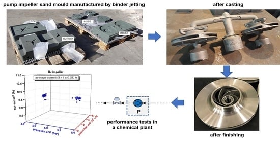
3.1. Fabrication Strategy by Combined Binder Jetting 3D Printing and Casting

Conventional manufacturing methods are limited mainly by the total production volume. For this reason, 3D printing is a valuable alternative when few copies of a given part are needed. In our case, the aim was to replace a very valuable old impeller used in the centrifugal pump of a polyol plant and compare the performances of the original and the 3D-printed copy. The sequential workflow is depicted in Figure 4 and involved the following steps:
  • analysis of the original part (KSB impeller);
  • part digitizing, CAD design, and 3D printing of the plastic model;
  • sand mould design and manufacturing;
  • casting using molten stainless steel and finishing (BJ impeller);
  • performance tests in a chemical plant and comparison with KSB impeller.
Since there were no original drawings of the KSB impeller available, the part was reverse engineered (Figure 5) using an industrial metrology 3D scanner bearing an optical automatic arm. This is a useful strategy when a precise digital model of a mechanical component needs to be reproduced [21]. After scanning, the small complex components were measured with an optical 3D coordinate measuring machine at up to 0.5 mm resolution to obtain the point cloud geometry. These points were then used to extrapolate the shape of the impeller, and finally, a parametric CAD model was made. Optical 3D coordinate measuring machines are replacing tactile measuring systems and gages because they capture more detailed and more easily interpretable information on an object in significantly shorter measuring times. Whereas old mechanical measuring systems captured data in a point-based or linear manner, optical measuring systems return full-field data about deviations between the actual 3D coordinates and the CAD data [41]. The point cloud geometry was revised and corrected before generating the STL file that the 3D printer understood and fabricating a “communication model” on PA12 plastic.
The 3D sand mould was fabricated using binder jetting on rapid prototyping silica. It was designed in separate pieces that assembled together to contain two impellers (Figure 6a,b) and had an excess dimension of 0.5 mm to account for material contraction after cooling. There were superior, intermediate, and bottom pieces that assembled like a puzzle. The fluid (liquid metal) entered through the superior part (cone shape inlet in Figure 6c) to fill internally, from down to top, the 3D features that generated the structure of the two impellers. Figure 6d shows photographs of the moulds after 3D printing, and Figure 7 shows photographs of the resulting casted impellers after mould separation. Excess casted material was then removed, and the parts were machine finished (Figure 8) and tested for dynamic balancing according to ISO 1940.

3.2. Characterization of the BJ Impeller

After casting and finishing, the BJ impeller was subjected to a series of dimensional and mechanical tests (Table 3). The finished part had a weight of 4.03 kg and a Brinell hardness of 183 as compared with the 212 of the original KSB impeller. The results of two-plane impeller dynamic balancing were within the permissible unbalance calculated according to ISO1940/1 for grade G 2.5 at an operating speed of 3000 rpm.
Table 4 shows the results of the dimensional characterization of the BJ impeller and a comparison with the dimensions specified by the manufacturer of the KSB impeller. A geometrical precision of ±0.1 mm was obtained with standard deviations for each dimension lower than 1%. The highest absolute dimensional discrepancy was obtained for dimension B, corresponding to the outside diameter of the impeller inlet, which may have been due to the finishing operations carried out after casting and removal of the excess materials (although in relative values, the deviation was only 0.28%). These results suggest that the 3D printing of the sand mould and subsequent metal casting are appropriate for generating relatively complex parts with sufficient precision to pass dimensional testing.
Examination via scanning electron microscope of the surface of a residual portion of casted material revealed the presence of cavities due to metal contraction during the cooling process that followed casting (Figure 9). These shrinkage voids [42] had variable shapes and sizes, from a few μm to ~400 μm, but accounted only for a very small portion of the surface (less than 0.5%). Assuming that these discontinuities were also present in the finished BJ impeller, they did not affect its performance (see Section 3.3).
A metallographic study carried out after thermal treatment gave some hints on its microstructure (Figure 10). Analysis of the resulting images showed a microstructure typical of a casting stainless steel 316 [43], with an austenitic matrix and elongated ferrite grains of 40 ± 10 μm length and 6–8 μm width. The proportion of the ferritic phase was 6.3%, as suggested by image analysis, and no chromium carbide precipitation was observed [44]. Comparison of the microstructure with a sample of a discarded KSB impeller revealed a similar pattern of a Cr/C-free austenitic matrix with ferrite islands but differing in size (120 ± 30 μm long, 10–15 μm width) and proportion (8.1%). These variations, although not considerable, indicate a faster cooling rate in the BJ impeller, resulting in the formation of a smaller ferrite precipitate.

3.3. Performance Tests of BJ Impeller in a Chemical Plant

The performance of the manufactured BJ impeller was then tested in a real scenario. The BJ impeller was mounted in a centrifugal pump located in a production plant of Dow Chemical Ibérica in Tarragona Site, Spain. This plant produces aqueous polyol/polyglycol solutions of different concentrations and viscosity by adjusting the proportions of feed materials (a polyol/polyglycol precursor and an antioxidant solution) in a discontinuous process. The pump (P) is located immediately after the reaction tank T and pushes the product mixture towards distillation column D (see Figure 3), and it is remotely supervised from a control room that collects several process parameters.
For the purpose of this study, the process parameters were first collected using the original KSB impeller during specific periods of time for three product recipes of high, medium, and low viscosity, as indicated in Table 1. Afterwards, the KSB impeller was substituted (on 30 October 2020) for the BJ, which was set to operate in identical operational conditions for the three recipes in order to compare its performance with that of the KSB impeller.
Figure 11, Figure 12 and Figure 13 show the results obtained for both impellers using the three recipes. Panels (a) and (b) in these figures show the dependence of pump amperage (current) on pressure and product flow, with typical values between 9 and 10 A. Since, in normal operating conditions, the electric tension of the pump is constant, a decrease in the current indicated a malfunction of mechanical parts of the pump in which the impeller was located and was thus an indirect measure of the performance of the pump. The average values in all cases were between 9.3 and 9.4 A, with low standard deviations, indicating similar behaviour of both impellers.
On the other hand, panels (c) and (d) in Figure 11, Figure 12 and Figure 13 show comparisons of the data obtained with both impellers for one typical production cycle. Average values and standard deviations are also indicated over each trace. A normal run lasted about two days, and parameter readings were taken continuously every 20 min. Pump P was continuously monitored to maintain the level of tank T at ~40%, and the variations in pressure and product flow observed in the figures correspond to adjustments in the production according to the desired specifications and production volume. Although we did not carry out a detailed statistical analysis of these results, it was evident that the parameter readings with the BJ impeller were comparable to, and in some cases slightly more stable than, those obtained with the original KSB impeller. This general trend was observed for all production cycles monitored, and no failure of the BJ impeller was observed throughout the performance study.
The results obtained indicated that there were no differences between the original and the new BJ manufactured impeller and further demonstrated that the manufacturing strategy was technically validated, from a design/manufacture point of view to an operational/process point of view.

4. Conclusions

Herein, we present a fabrication and performance study of a stainless-steel pump impeller manufactured by BJ printing of a sand mould followed by casting. The main conclusions of the work can be summarized as follows:
  • Reverse engineering of the original impeller allowed creating a polyamide copy, used to validate the CAD design by metrological characterization, with a dimensional accuracy of 99.6%.
  • This work is another example of the advantages of BJ sand printing in creating multicomponent moulds able to recreate complex features of the original part.
  • The casted material showed an essentially homogeneous surface, with a very small proportion (<0.5%) of shrinkage voids. The microstructure was similar to that of the original impeller, with 6.3% of ferritic phase.
  • The operational performance of the produced impeller was tested in a real scenario by installing the impeller in a centrifugal pump. The pump operated in a polyol/polyglycol plant, and a series of process parameters related to the pump behaviour were measured continuously for three production recipes varying in final concentration and viscosity.
  • For example, at 500 cSt of product viscosity, the average current consumption of the pump was 9.34 A, as compared with 9.41 A measured with the original impeller, with standard deviations of 0.3% and 2.7%, respectively, for a wide interval of pressures (4–6 bar) and flows (2000–6000 L/h).
  • The parameters were also comparable when measured during a complete production cycle. This indicated that both impellers had equivalent performance, thus validating the fabrication strategy from an operational point of view.
Therefore, this work demonstrated that the implementation of additive manufacturing technologies in chemical process engineering is a useful solution for fabricating spare parts of high added value that are difficult to replicate with other technologies, with consequent economic benefit. Further work should focus on comparing the initial mechanical and morphological properties of the BJ impeller with those obtained after one year of operation in order to understand possible changes induced by the stress associated with continuous operation. In addition, a next step will involve the fabrication of an impeller by direct metal 3D printing and an economic study of the possible wider implementation of both 3D printing technologies in the chemical plant.

Author Contributions

Conceptualization: F.H and A.F.; methodology and experimentation, F.H.; data curation, F.H.; writing—original draft preparation, F.H.; writing—review and editing, A.F.; supervision, A.F. All authors have read and agreed to the published version of the manuscript.

Funding

This work received no external funding.

Institutional Review Board Statement

Not applicable.

Informed Consent Statement

Not applicable.

Data Availability Statement

All data are included in the article.

Acknowledgments

We thank Ángela Moreno (Dow Industrial Solutions, Production Leader Polyglycol/Utilities Plant), Mario Domínguez (Dow Chemical Senior Technology Manager, Rotating Equipment), Albert Romagosa (Dow Chemical, Improvement Manager), and Oscar Alonso (Leitat, Energy and Engineering Department) for their valuable support and contributions to the finalization of this work.

Conflicts of Interest

The authors declare no conflict of interest.

References

  1. Gao, W.; Zhang, Y.; Ramanujan, D.; Ramani, K.; Chen, Y.; Williams, C.; Wang, C.; Shin, Y.; Zhang, S.; Zavattieri, P. The status, challenges, and future of additive manufacturing in engineering. Comput. Aided Des. 2015, 69, 65–89. [Google Scholar] [CrossRef]
  2. Talamona, D.; Mukhtarkhanov, M.; Perveen, A. Application of Stereolithography Based 3D Printing Technology in Investment Casting. Micromachines 2020, 11, 946. [Google Scholar]
  3. Redwood, B.; Schöffer, F.; Garret, B. The 3D Printing Handbook: Technologies, Design and Applications; 3D Hubs. B.V.: Amsterdam, The Netherlands, 2017. [Google Scholar]
  4. Wohlers, T.; Campbell, I.; Diegel, O.; Huff, R.; Kowen, J. Wohles Report 2020. Additive Manufacturing and 3D Printing, State of the Industry; Wohlers Associates: Fort Collins, CO, USA, 2020. [Google Scholar]
  5. Femmer, T.; Flack, I.; Wessling, M. Additive Manufacturing in Fluid Process Engineering. Chem. Ing. Tech. 2016, 88, 535–552. [Google Scholar] [CrossRef]
  6. Zentel, K.; Fassbender, M.; Pauer, W.; Luinstra, G. 3D printing as chemical reaction engineering booster. Adv. Polym. React. Eng. 2020, 56, 97–137. [Google Scholar]
  7. Kotz, F.; Risch, P.; Helmer, D.; Rapp, B. High-Performance Materials for 3D Printing in Chemical Synthesis Applications. Adv. Mater. 2019, 31, 1805982. [Google Scholar] [CrossRef]
  8. Maier, M.; Lebl, R.; Sulzer, P.; Lechner, J.; Mayr, T.; Zadravec, M.; Slama, E.; Pfanner, S.; Schmölzer, C.; Pöchlauer, P.; et al. Development of customized 3D printed stainless steel reactors with inline oxygen sensors for aerobic oxidation of Grignard reagents in continuous flow. React. Chem. Eng. 2019, 4, 393–401. [Google Scholar] [CrossRef] [Green Version]
  9. Belka, M.; Bączek, T. Additive manufacturing and related technologies—The source of chemically active materials in separation science. Trends Anal. Chem. 2021, 142, 116322. [Google Scholar] [CrossRef]
  10. Zhu, J.; Wu, P.; Chao, Y.; Yu, J.; Zhu, W.; Liu, Z.; Xu, C. Recent advances in 3D printing for catalytic applications. Chem. Eng. J. 2022, 433, 134341. [Google Scholar] [CrossRef]
  11. Chen, C.; Mehl, B.; Munshi, A.; Townsend, A.; Spence, D.; Martin, R. 3D-printed microfluidic devices: Fabrication, advantages and limitations—A mini review. Anal. Meth. 2016, 8, 6005–6012. [Google Scholar] [CrossRef]
  12. Hock, S.; Rose, M. 3D-Structured Monoliths of Nanoporous Polymers by Additive Manufacturing. Chem. Ing. Tech. 2020, 92, 525–531. [Google Scholar] [CrossRef] [Green Version]
  13. Zhao, L.; Zeng, G.; Gu, Y.; Tang, Z.; Wang, G.; Tang, T.; Shan, Y.; Sun, Y. Nature inspired fractal tree-like photobioreactor via 3D printing for CO2 capture by microaglae. Chem. Eng. Sci. 2019, 193, 6–14. [Google Scholar] [CrossRef]
  14. Ligon, S.; Liska, R.; Stampfl, J.; Gurr, M.; Mülhaupt, R. Polymers for 3D Printing and Customized Additive Manufacturing. Chem. Rev. 2017, 117, 10212–10290. [Google Scholar] [CrossRef] [PubMed] [Green Version]
  15. Gal-Or, E.; Gershoni, Y.; Scotti, G.; Nilsson, S.; Saarinen, J.; Jokinen, V.; Strachan, C.; Boije af Gennäs, G.; Yli-Kauhaluoma, J.; Kotiaho, T. Chemical analysis using 3D printed glass microfluidics. Anal. Meth. 2019, 11, 1802–1810. [Google Scholar] [CrossRef] [Green Version]
  16. Gyak, K.; Vishwakarma, N.; Hwang, Y.; Kim, J.; Yun, H.; Kim, D. 3D-printed monolithic SiCN ceramic microreactors from a photocurable preceramic resin for the high temperature ammonia cracking process. React. Chem. Eng. 2019, 4, 1393–1399. [Google Scholar] [CrossRef]
  17. Vafadar, A.; Guzzomi, F.; Rassau, A.; Hayward, K. Advances in Metal Additive Manufacturing: A Review of Common Processes, Industrial Applications, and Current Challenges. Appl. Sci. 2021, 11, 1213. [Google Scholar] [CrossRef]
  18. Bandyopadhyay, A.; Zhang, Y.; Bose, S. Recent developments in metal additive manufacturing. Curr. Opin. Chem. Eng. 2020, 28, 96–104. [Google Scholar] [CrossRef]
  19. Vaezi, M.; Drescher, P.; Seitz, H. Beamless Metal Additive Manufacturing. Materials 2020, 13, 922. [Google Scholar] [CrossRef] [Green Version]
  20. Kladovasilakis, N.; Kontodina, T.; Charalampous, P.; Kostavelis, I.; Tzetzis, D.; Tzovaras, D. A case study on 3D scanning, digital reparation and rapid metal additive manufacturing of a centrifugal impeller. IOP Conf. Ser. Mat. Sci. Eng. 2021, 1037, 012018. [Google Scholar] [CrossRef]
  21. Ponticelli, G.; Tagliaferri, F.; Venettacci, S.; Horn, M.; Giannini, O.; Guarino, S. Re-Engineering of an Impeller for Submersible Electric Pump to be Produced by Selective Laser Melting. Appl. Sci. 2021, 11, 7375. [Google Scholar] [CrossRef]
  22. Shakil, S.; Smith, N.; Yoder, S.; Ross, B.; Alvarado, D.; Hadadzadeh, A.; Haghshenas, M. Post fabrication thermomechanical processing of additive manufactured metals: A review. J. Manuf. Proc. 2022, 73, 757–790. [Google Scholar] [CrossRef]
  23. Lynch, P.; Hasbrouck, C.R.; Wilck, J.; Kay, M.; Manogharan, G. Challenges and opportunities to integrate the oldest and newest manufacturing processes: Metal casting and additive manufacturing. Rapid Prototyp. J. 2020, 26, 1145–1154. [Google Scholar] [CrossRef]
  24. Sivarupan, T.; Balasubramani, N.; Saxena, P.; Nagarajan, D.; El Mansori, M.; Salonitis, K.; Jolly, M.; Dargusch, M. A review on the progress and challenges of binder jet 3D printing of sand moulds for advanced casting. Addit. Manuf. 2021, 40, 101889. [Google Scholar] [CrossRef]
  25. Mostafaei, A.; Elliott, A.; Barnes, J.; Li, F.; Tan, W.; Cramer, C.; Nandwana, P.; Chmielus, M. Binder jet 3D printing—Process parameters, materials, properties, modeling, and challenges. Prog. Mater. Sci. 2021, 119, 100707. [Google Scholar] [CrossRef]
  26. Zheng, J.; Chen, A.; Zheng, W.; Zhou, X.; Bai, B.; Wu, J.; Ling, W.; Ma, H.; Wang, W. Effectiveness analysis of resources consumption, environmental impact and production efficiency in traditional manufacturing using new technologies: Case from sand casting. Energy Convers. Manag. 2020, 209, 112671. [Google Scholar] [CrossRef]
  27. Shangguan, H.; Kang, J.; Yi, J.; Deng, C.; Hu, Y.; Huang, T. Controlled cooling of an aluminum alloy casting based on 3D printed rib reinforced shell mold. China Foundry 2018, 15, 210–215. [Google Scholar] [CrossRef] [Green Version]
  28. Deng, C.; Kang, J.; Shangguan, H.; Hu, Y.; Huang, T.; Liu, Z. Effects of hollow structures in sand mold manufactured using 3D printing technology. J. Mater. Process. Technol. 2018, 255, 516–523. [Google Scholar] [CrossRef]
  29. Snelling, D.; Li, Q.; Meisel, N.; Willaims, C.B.; Batra, R.C.; Druschitz, A.P. Lightweight metal cellular structures fabricated via 3D printing of sand cast molds. Adv. Eng. Mater. 2015, 17, 923–932. [Google Scholar] [CrossRef]
  30. Gill, S.S.; Kaplas, M. Efficacy of powder-based three-dimensional printing (3DP) technologies for rapid casting of light alloys. Int. J. Adv. Manuf. Technol. 2011, 52, 53–64. [Google Scholar] [CrossRef]
  31. Martinez, D.; Bate, C.; Manogharan, G. Towards Functionally Graded Sand Molds for Metal Casting: Engineering Thermo-mechanical Properties Using 3D Sand Printing. JOM 2020, 72, 1340–1354. [Google Scholar] [CrossRef]
  32. Sundaram, D.; Svidró, J.T.; Svidró, J.; Diószegi, A. On the Relation between the Gas-Permeability and the Pore Characteristics of Furan Sand. Materials 2021, 14, 3803. [Google Scholar] [CrossRef]
  33. Mitra, S.; EL Mansori, M.; Rodríguez de Castro, A.; Costin, M. Study of the evolution of transport properties induced by additive processing sand mold using X-ray computed tomography. J. Mater. Process. Technol. 2020, 277, 116495. [Google Scholar] [CrossRef] [Green Version]
  34. Gill, S.; Kaplas, M. Comparative Study of 3D Printing Technologies for Rapid Casting of Aluminium Alloy. Mater. Manuf. Proc. 2009, 24, 1405–1411. [Google Scholar] [CrossRef]
  35. Shangguan, H.; Kang, J.; Deng, C.; Hu, Y.; Huang, T. 3D-printed shell-truss sand mold for aluminum castings. J. Mater. Proc. Technol. 2017, 250, 247–253. [Google Scholar] [CrossRef]
  36. Sama, S.; Badamo, T.; Lynch, P.; Manogharan, G. Novel sprue designs in metal casting via 3D sand-printing. Addit. Manuf. 2019, 25, 563–578. [Google Scholar] [CrossRef]
  37. Sama, S.; Badamo, T.; Manogharan, G. Case Studies on Integrating 3D Sand-Printing Technology into the Production Portfolio of a Sand-Casting Foundry. Int. J. Metalcast. 2019, 14, 12–24. [Google Scholar] [CrossRef]
  38. Scime, L.; Beuth, J. Using machine learning to identify in-situ melt pool signatures indicative of flaw formation in a laser powder bed fusion additive manufacturing process. Addit. Manuf. 2019, 25, 151–165. [Google Scholar] [CrossRef]
  39. Pagone, E.; Saxena, P.; Papanikolaou, M.; Salonitis, K.; Jolly, M. Sustainability Assessment of Rapid Sand Mould Making Using Multi-criteria Decision-Making Mapping. In Sustainable Design and Manufacturing 2020. Smart Innovation, Systems and Technologies; Scholz, S.G., Howlett, R.J., Setchi, R., Eds.; Springer: Singapore, 2021; Volume 200, pp. 345–355. [Google Scholar]
  40. Mitchell, A.; Lafont, U.; Hołyńska, M.; Semprimoschnig, C. Additive Manufacturing—A Review of 4D Printing and Future Applications. Addit. Manuf. 2018, 24, 606–626. [Google Scholar] [CrossRef]
  41. Vora, H.D.; Sanyal, S. A comprehensive review: Metrology in additive manufacturing and 3D printing technology. Prog. Addit. Manuf. 2020, 5, 319–353. [Google Scholar] [CrossRef]
  42. Khalajzadeh, V.; Beckermann, C. Simulation of Shrinkage Porosity Formation During Alloy Solidification. Metall. Mater. Trans. A 2020, 51, 2239–2254. [Google Scholar] [CrossRef] [Green Version]
  43. Vander Voort, G.; Lucas, G.; Manilova, E. Metallography and Microstructures of Stainless Steels and Maraging Steels. In Metallography and Microstructures; ASM International: Materials Park, OH, USA, 2004; pp. 670–700. [Google Scholar]
  44. Astafurov, S.; Astafurova, E. Phase Composition of Austenitic Stainless Steels in Additive Manufacturing: A Review. Metals 2021, 11, 1052. [Google Scholar] [CrossRef]
Figure 1. Digitalization and CAD design for BJ impeller fabrication.
Applsci 12 03539 g001
Figure 2. Design and manufacturing of the sand mould.
Applsci 12 03539 g002
Figure 3. Work process flowchart at the polyol/polyglycol plant. The impeller was mounted in pump P. T: reaction tank, D: distillation column, V-A and V-B: fail-open valves.
Applsci 12 03539 g003
Figure 4. Workflow employed for the fabrication of the BJ impeller.
Applsci 12 03539 g004
Figure 5. Impeller digitizing and design: (a) 3D scan with curves, (b) solid surface view, (c,d) PA12 communication model.
Applsci 12 03539 g005
Figure 6. (a) Transparent and (b) cross-section 3D views of the sand moulds. (c) Model views of the impeller fills at the initial (left) and final (right) moments. (d) Photographs of the manufactured 3D sand moulds indicating the different parts.
Applsci 12 03539 g006
Figure 7. View of the impellers after casting, cooling, and mould separation: (a) top view, (b) downside view.
Applsci 12 03539 g007
Figure 8. View of the final BJ impellers manufactured before (a) and after (b) machining finish. (c) Original KSB impeller.
Applsci 12 03539 g008
Figure 9. SEM images of BJ impeller surface showing (a) large (~400 μm) and (b) small (~50 μm) shrinkage voids due to metal contraction.
Applsci 12 03539 g009
Figure 10. Microstructure images of (a) BJ impeller, (b) KSB impeller.
Applsci 12 03539 g010
Figure 11. Recipe 1. (a,b) Dependence of pump amperage (current) on pump pressure and polyol flow for two consecutive production cycles. (c,d) Tank level, polyol flow, and pump pressure, read continuously for a complete production cycle. KSB impeller (a,c), BJ impeller (b,d).
Applsci 12 03539 g011
Figure 12. Recipe 2. (a,b) Dependence of pump amperage (current) on pump pressure and polyol flow for two consecutive production cycles. (c,d) Tank level, polyol flow, and pump pressure, read continuously for a complete production cycle. KSB impeller (a,c), BJ impeller (b,d).
Applsci 12 03539 g012
Figure 13. Recipe 3. (a,b) Dependence of pump amperage (current) on pump pressure and polyol flow for two consecutive production cycles. (c,d) Tank level, polyol flow, and pump pressure, read continuously for a complete production cycle. KSB impeller (a,c), BJ impeller (b,d).
Applsci 12 03539 g013
Table 1. Composition (%) of the cast stainless steel used in this work.
ElementFeCrNiCMo
%6319110.72
Table 2. Product recipe compositions and test durations.
RecipeFinal Product PropertiesDuration of Tests
Concentration
(% w/v)
Viscosity
(cSt)
KSB ImpellerBJ Impeller
180500January 2020–October 2020November 2020–April 2021
250180August 2019–October 2020November 2020–April 2021
32030May 2019–October 2020November 2020–April 2021
Table 3. Mechanical properties of the BJ impeller.
PropertyValues 1
Relative Density (g cm−3)7.89 ± 0.05
Hardness (Brinell)183 ± 5
Dynamic
Balancing 2
Plane 1 3Before Balancing: 6.5 g @ 90° (13 g·mm)
After Balancing: 0.3 g @ 93° (0.6 g·mm)
Plane 2 3Before Balancing: 17.8 g @ 160° (35.6 g·mm)
After Balancing: 0.9 g @ 150° (1.8 g·mm)
1 Average of two measurements. 2 Calculated permissible unbalance per plane (G 2.5): 15.9 g·mm. 3 See inset figure in Table 4.
Table 4. Dimensional characterization of the BJ impeller.
Applsci 12 03539 i001
DimensionSpecification (mm)Measured (mm)Difference (mm) 1% Deviation 2
A206.0 ± 0.5205.99 ± 0.01−0.010.01
B94.5 ± 0.594.23 ± 0.26−0.270.28
C68.6 ± 0.368.70 ± 0.130.10.19
D14.0 ± 0.214.07 ± 0.070.070.50
E5.0 ± 0.15.05 ± 0.050.050.99
F20.0 ± 0.119.94 ± 0.05−0.060.25
G36.0 ± 0.236.02 ± 0.040.020.11
1 Difference between measured and specification. 2 (standard deviation—measured dimensions) × 100.
Publisher’s Note: MDPI stays neutral with regard to jurisdictional claims in published maps and institutional affiliations.

