1. Introduction
Starting from the variants studied within the Laboratory of Invention and Technological Transfer of the University of Suceava [
1,
2,
3,
4], in which the elastic elements of materials with shape memory were tested in different ways, an application was developed that allows the life of the materials to be monitored and tested, by subjecting them to a significant number of tests (heating—cooling), controlling them with an electric current, and self-heating the nitinol element above the transition temperature, which generates internal forces due to changes in the crystalline structure of the alloy. In this paper, the tested element is in the form of a superelastic nitinol spring, often used in dentistry, with a length of 20 mm and a wire diameter of 0.7 mm.
Applications based on thermal memory can be free return (medicine, engineering—autonomous heliotrope) [
5,
6,
7], with retained return (hydro-pneumatic couplings, electrical connectors, fasteners and space applications) or mechanical work generators [
8,
9,
10,
11]. Mechanical work generating applications are mainly used in the construction of actuators (actuators), sensors and heat engines. Depending on how the energy that is transformed into mechanical work is supplied, the actuators can be thermal or electric [
12].
The most well-known examples of the use of thermal actuators with shape memory are: fire protection by detecting a predetermined temperature (by varying resistivity), temperature control in refrigeration systems, thermal protection of water filters, steam control in heating systems, etc. Shape memory electric actuators only have the function of performing mechanical work. In applications, they successfully replace conventional actuators, such as electromagnetic solenoids, electric, pneumatic, or hydraulic servomotors and motors that are superior in compactness, quieter operation, and simplicity. In addition to robotics, where the most successful applications of electric actuators with shape memory (micromanipulators, submarine robotic crabs) were made, they were also introduced in other fields: the automotive industry, the protection of electrical circuits from overheating, and proportional control [
13].
Electric actuators that use shape memory alloys are real alternatives to conventional actuators [
14,
15]. The advantage of these is that they create a good reason to reduce the size, weight and complexity of robotic systems. Additionally, shape memory electric actuators are particularly compact and simple, and the weight-to-force ratio is remarkable. A noteworthy advantage is the silence they show during operation.
In addition to all these advantages in many applications, there are some disadvantages, including the low efficiency, with the specification that an electric actuator with shape memory is actually a heat engine where the material used converts heat energy into mechanical work by way of the Joule effect. The operating cycle is quite slow and directly dependent on the applied electric current and how it is self-heated to perform useful mechanical work. However, the main parameter that affects the operating cycle is the ambient temperature at which the actuator operates [
16].
2. Thermomechanical Behavior of the Ni-Ti Material
Given the properties of Ni-Ti, two aspects of phase transformations are significant. The first is that the transformation is reversible, which means that heating, above the transformation temperature, leads to the return of the crystalline structure of the austenite phase. The second key aspect is the transformation in both directions [
17,
18,
19].
The cooling/heating cycle represents the thermal hysteresis of Ni-Ti transformation. The temperature difference between the two phases, austenite and martensite, is due to the composition of the two metals and the precision of processing.
When a shape memory alloy is in the austenite phase, it is exposed to extremely elastic behavior. This is known as the pseudoelastic effect or pseudoelasticity. Although pseudoelasticity is an important feature of shape memory alloys, typical of applications of these materials, it requires the use of the shape memory effect, which is a result of temperature-induced transformation. The value of this transformation temperature depends on the composition of the alloy [
20,
21].
Pseudoelasticity, or superelasticity as it is also called, is caused by stress-assisted martensitic transformations, the term proposed later and currently accepted being that of stress-induced martensitic transformation (MIT) at constant austenitic temperatures.
Pseudoelasticity can be considered as any nonlinearity on the stress–strain curve during discharge. Depending on the percentage by which it occurs, pseudoelasticity can be maclating or transforming. Pseudoelasticity of maclating occurs in metallic materials that deform by maclating [
22]. Unlike the normal elastic return from unloading, the pseudoelasticity of maclating is manifested by an additional elastic return of approximately 0.8%.
The general term under which the pseudoelasticity of maclare is found is pseudo-maclare. It should be noted that an alloy with pseudomaclat shape memory loses its additional recovery if it is kept in a deformed state due to the rearrangement of pseudomaclat which is brought to s more stable position [
22,
23,
24,
25].
Transformation pseudoelasticity is due to a stress-induced martensitic transformation and cannot occur at temperatures above the critical transformation point.
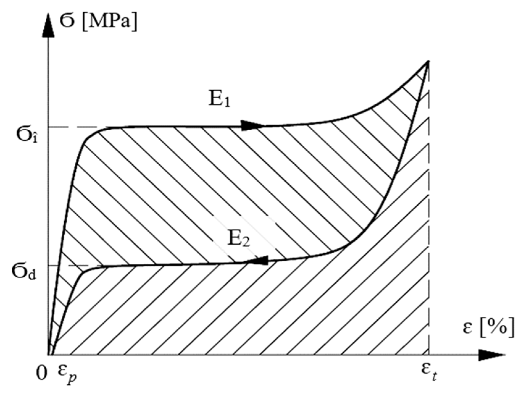
Figure 1 defines the typical mechanical parameters of the transformation superelasticity for a schematic stress–strain curve [
18,
19,
22]. Thus, the following are defined:
Ϭî—the load plate voltage,
Ϭd—the discharge plate voltage,
E1—the energy dissipated during a PSE cycle (transformation hysteresis),
E2—the energy released for download.
Based on these mechanical parameters, two more fundamental characteristics are defined for the study of transformation superelasticity [
18,
19].
- degree of elongation recovery:
where
ɛt—the total relative elongation and
ɛp—the permanent relative elongation;
- energy storage efficiency:
It is observed that in order to be usable, superelasticity, which is one of the most useful manifestations of the shape memory effect, must have a degree of elongation recovery as close as 100% and a high yield [
22].
The first condition depends on several factors (temperature, total relative elongation, speed of deformation, chemical composition, degree of hardening, heat treatment, etc.). For the second condition, it is obvious that the increase in the efficiency presupposes a higher stiffness of the initial phase, a higher charging voltage and a lower dissipated energy E1.
The ability to store elastic energy has proven to be one of the basic characteristics of shape memory alloys. In the case of transformation superelasticity, this capacity, together with the recoverable elongation, represent the most useful properties, having values much higher than the classic elastic materials [
18]. Therefore, for Ni-Ti, the values will be
ɛt = 10% and
E2 = 42 J/cm
3.
3. Ni-Ti Spring Test Platform
The application is based on a microcontroller system connected with a force sensor, a temperature sensor that monitors the ambient temperature and electrical components needed to power the self-heating system. The data taken during the operation are stored in an Excel file with the extension .csv, which can be downloaded from the ThingSpeak.com site, in which parameters read at set time intervals are passed.
The parameter that will have to be monitored with the help of this application is the force developed by the elastic system. In this sense, the nitinol was positioned on the test stand in the form of a deformed spring, the initial shape being stored in compressed form, in which one of the ends is fixed and the force sensor is attached to the other end. Its power supply is made from the outside by means of a direct current source switched with a microcontroller controlled relay.
The calibration of the experimental stand was performed using a standard with a mass of 1 kg, in which the force sensor was calibrated at 9.8 N.
By using a microcontroller, the following parameters can be monitored: the period in which the relay closes the self-heating circuit; the time in which the nitinol spring is traversed by an electric current, which determines the self-heating; the period in which the force developed by the element; the ambient temperature; the number of switches; the number of tests; and the period in which it is at rest, i.e., a rest period, which allows the element to cool down.
4. Experimental Results
During the tests, two types of determinations were made regarding the fatigue strength of nitinol, in which the Ni-Ti was fed at a current I1 of about 50% and another current I2 of 85% of the maximum current. The maximum current for the tested element was 1.1 A, representing the threshold value above which the material is destroyed.
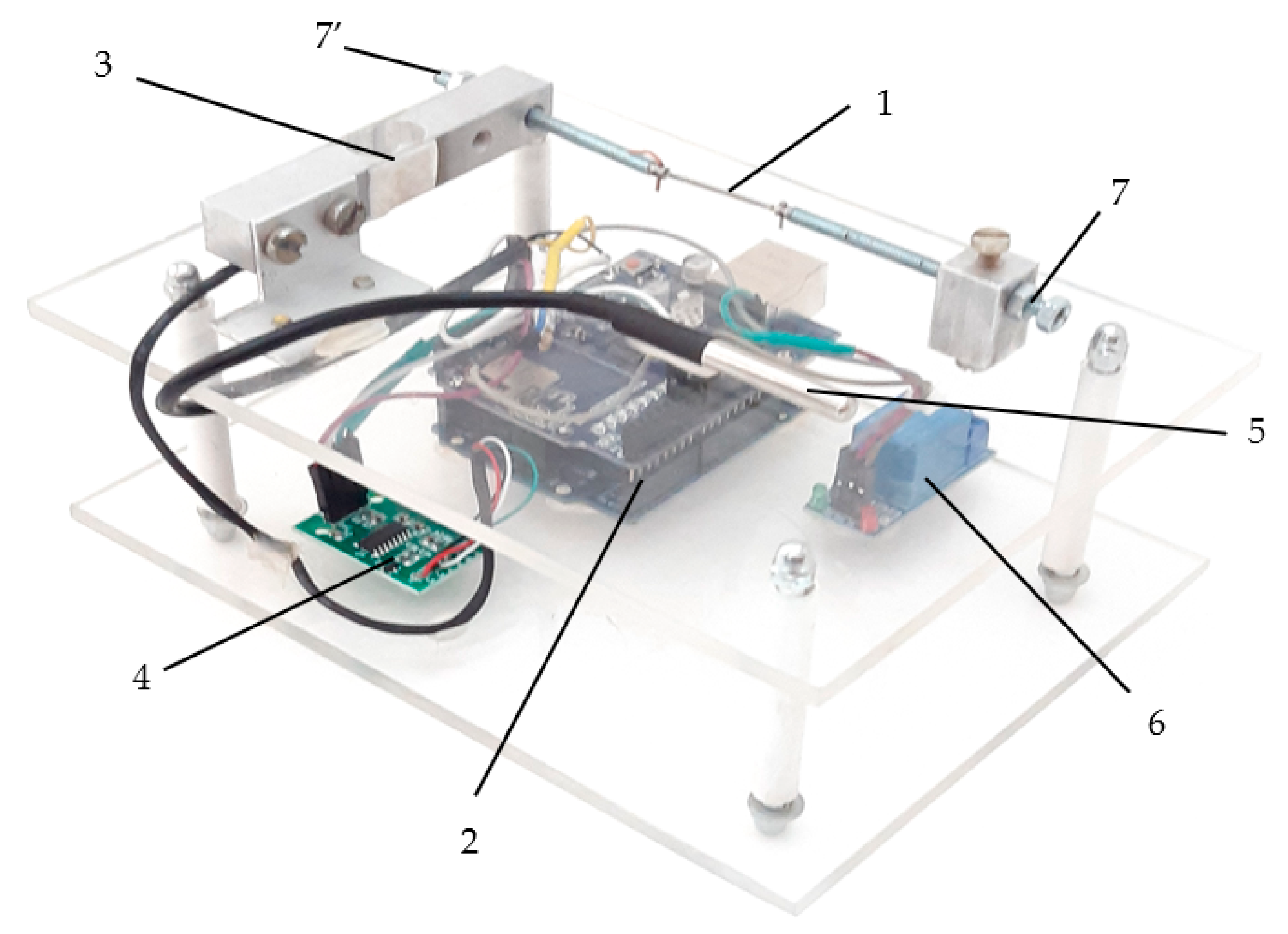
In the first variant, the experimental stand in
Figure 2 operated for a period of 19 days in which over 100,000 trials were registered. In order to be considered a test, a relay actuation time, Ni-Ti supply time respectively, of 5 s was established. In the second n-1, the microcontroller was programmed to read the parameters of the sensors mounted on the stand. After the actuation period, a rest period of 10 s followed, at which point the tested element was allowed to cool.
When operating the relay in the closed position, for a period of 5 s, which was established in the tests, the nitinol element was supplied from a direct current source, with a constant voltage of 1.23 V, crossed by an electric current I1 = 0.615 A, which determines its self-heating due to its own resistance and generates a force of approximately 1.6 N, according to the force sensor on the stand.
The tests were performed in a thermally insulated enclosure in which the ambient temperature was maintained at approximately 26 °C. In
Table 1, a slight increase can be observed in temperature in the enclosure during the test due to heating and cooling cycles of the test element, which affects the air inside the heating chamber.
Table 1 shows the values read using the ThingSpeak platform at the applied electric current I
1 set by the user. The number of readings is specified, the reading being performed by the microcontroller at a prescribed time interval for data collection, the number of tests (actuation—rest), actuation time and rest time can be set by the user, as can the ambient temperature at which the test was performed and the force generated by the active element being tested.
Due to the configuration of the microcontroller system, being connected to an Internet network, it was possible to view, analyze and download data in real time using the ThingSpeak platform being produced by MathWorks. The ThingSpeak platform provides analysis and visualization of live data streams in the cloud being posted by devices or equipment connected via the Internet.
Analyzing the two images in
Figure 3, it is observed that the maximum temperature reached by the active element in nitinol while being fed is about 55 °C, and then it cools significantly during the 10 s of rest to about 34 °C. The cooling was carried out freely, in the natural environment, with an ambient temperature of approximately 27 °C.
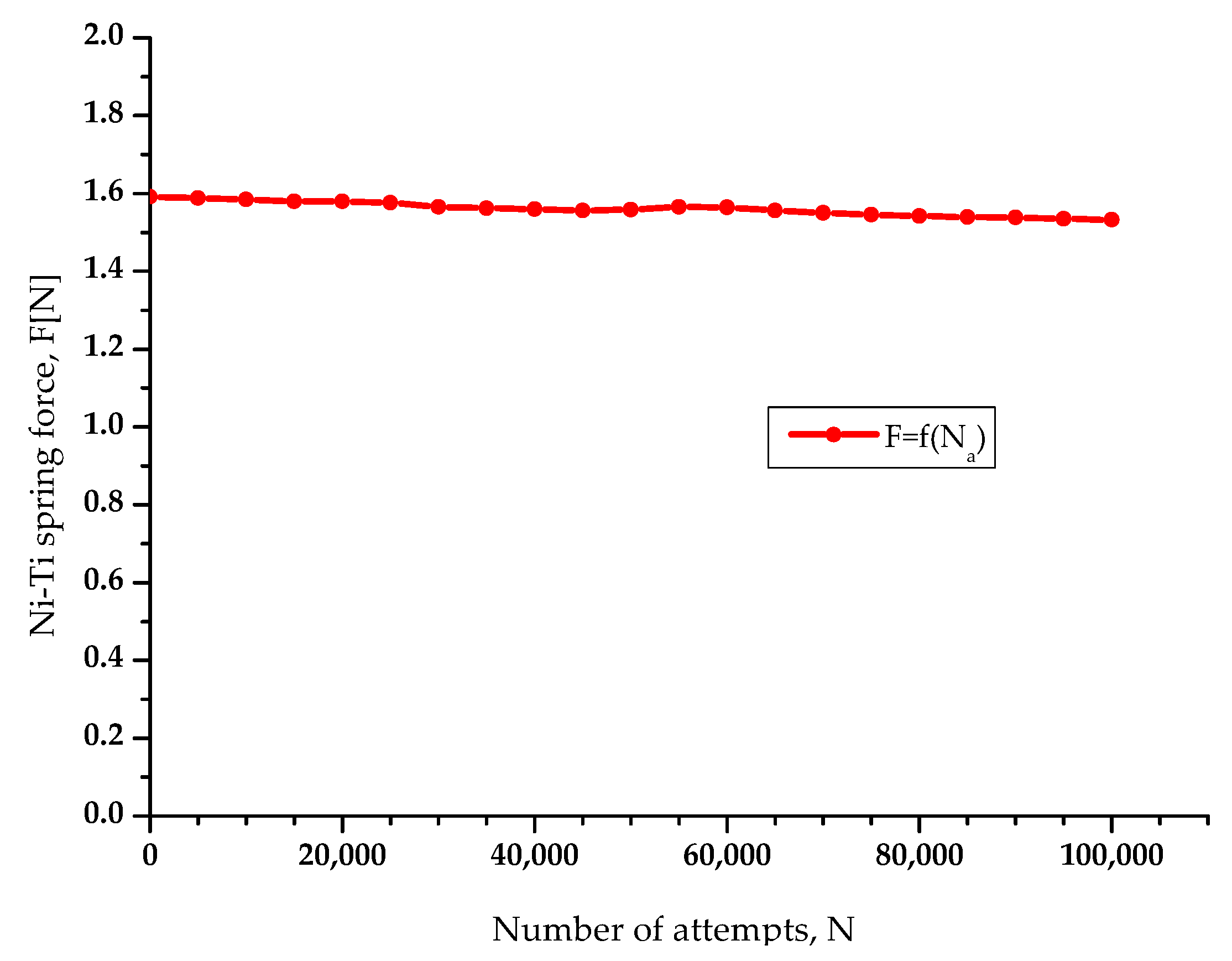
The force generated by the nitinol spring, at over 100,000 tests is approximately constant, with a value of 1.6 N (
Figure 4). There are small decreases in the force value, which is due to the variation in ambient temperature but also the possible variation in the current flowing through the element.
Some experimental data are presented below, collected using the operation of nitinol spring, and the main purpose of this test is to check the Nitinol material for fatigue.
Analyzing and averaging the ambient temperature at which the tests were performed, we can draw a conclusion about the change in temperature of ±0.5 °C, so it can not be said that this change will substantially influence the force generated by the nitinol spring; however, if we analyze the curve in
Figure 5, the allure of the force-ambient temperature variations indicates a slight decrease in the force with the increase in the temperature at differences greater than ±1 °C.
Increasing the ambient temperature by more than 2.5 °C, without reaching the crystalline structure’s temperature of change, can lead to a change of only 0.08 N, which emphasizes the immunity of the system to these small variations in microclimate.
In the second stage of the tests, in which case the electric current I
2 injected into the Ni-Ti is 0.914 A, higher than the first test, being close to the maximum current that can be injected without damaging the active element, the system operated for a period of almost 5 days, performing over 25,000 attempts. The test was performed under the same conditions as the previous one with the same actuation time of 5 s, followed by a 10 s cooling pause, the results obtained being presented in
Table 2.
The images in
Figure 6 illustrate the maximum temperature reached by the tested Ni-Ti during the actuation period of up to 95 °C (
Figure 6a), followed by a cooling in the rest period of 10 s to approximately 43 °C (
Figure 6b).
This time, it was possible to observe a rapid aging effect of the element because the temperature to which it was subjected was much higher, which damaged its crystalline structure, thus giving up not only the initially memorized shape, but also the internal forces generated.
Analyzing the graph in
Figure 7, we can see the evolution of the force generated by the active element in over 25,000 tests. After initially starting from a force of 4.3 N at the applied electric current I2, this was followed by a continuous decrease to about 20,000 tests, followed by a more pronounced drop in the allure of the characteristic, due to the failure of the thermal stress of the element of nitinol, to an approximately zero force.
The image in
Figure 8 shows the difference between the Ni-Ti elements of the two tests. The first element (
Figure 8a) was tested at current I1, and the final shape is identical to the original one, which means that it has kept its properties. The second element (
Figure 8b) was tested at current I2 and eventually underwent a change in shape and color, making it darker, which also showed the loss of the properties of intelligent material.
5. Conclusions
The test stand was used to test and evaluate the characteristics of smart materials, to understand how they respond to various thermal stimuli and how they can be used in the development of technical eq/uipment based on Ni-Ti with nitinol. Tests performed in the research laboratory found that Joule heating of the active elements by applying an electric current to its terminals is more efficient than heating using external sources.
The elastic systems have been tested individually, and the application is intended to analyze the response to fatigue resistance. In the tests, a comparison was made applying two different stimulation currents in order to evaluate the use of active elements for the development of applications based on electric current control.
The first variant, on which an I1 current of approximately 50% of the maximum current tested in the laboratory was applied, which can damage the element, demonstrates that after a very large number of cycles repeated continuously for 19 days of operation, under the same conditions, it retains the elastic characteristics and can therefore be used in the industrial field, but also in medicine and in the automotive industry. The second test shows that when applying an I2 current, at 85% of the maximum current, which can damage the active element, even if initially a high performance is achieved on the generated force and more precise control of the element with a reduced time constant, it it permanently loses the properties of shape memory, which decreases its lifespan by applying a higher current, elastic performance, shape and making it impossibile to be reused.
For the best possible analysis of Ni-Ti samples, the factors that can substantially influence their accuracy must be taken into account: the temperature of the external environment, the air flows around the active elements, the temperature at which the alloy is activated, the overall size necessary to control them.
The transient regime of the nitinol spring element is influenced by the ambient temperature and the small construction errors of the test stand. In order to reduce these disadvantages, a thermal insulation of the tested element and a high accuracy of the measurements regarding its movement over time can be achieved.
Following the testing of nitinol elements of several types and shapes, under different conditions and through the development of applications in the Laboratory of Invention and Technology Transfer of the Stefan cel Mare University of Suceava, several aspects were highlighted regarding the behavior of the material with shape memory, namely behavior such as having a non-linear characteristic in operation, which are strongly influenced by ambient temperature and air currents. The transition temperature point is a very important aspect in choosing the alloy for various applications; it can be easily controlled by supplying it to a voltage source, with the possibility of generating the necessary force depending on the applied electric current. Additionally, it is in the form of springs and straight wire, and it is necessary to store it in certain shapes as needed; the storage methods are complex, requiring constant high temperatures and requiring the storage form to be maintained. The cycles have to be repeated several times until it is set to the desired shape. Additionally, systems that use drives using shape memory materials have high reliability, simplicity of construction and advantages in terms of size and mass, allowing many applications to be developed, the fields of application ranging from the toy industry, the energy industry, automation, the automotive industry and the aerospace industry to the field of medical engineering.


 ,
, 


