Article

Resonant Magnetoelectric Effect at Low Frequencies in Layered Polymeric Cantilevers Containing a Magnetoactive Elastomer

1
Research and Educational Center “Magnetoelectric Materials and Devices”, MIREA–Russian Technological University, Pr. Vernadskogo, 78, 119454 Moscow, Russia
2
East Bavarian Centre for Intelligent Materials (EBACIM), Ostbayerische Technische Hochschule (OTH) Regensburg, Seybothstr. 2, D-93053 Regensburg, Germany
*
Authors to whom correspondence should be addressed.
Appl. Sci. 2022, 12(4), 2102; https://doi.org/10.3390/app12042102
Submission received: 17 December 2021 / Revised: 9 February 2022 / Accepted: 14 February 2022 / Published: 17 February 2022

Abstract

:
In this work, the resonance enhancement of magnetoelectric (ME) coupling at the two lowest bending resonance frequencies was investigated in layered cantilever structures comprising a magnetoactive elastomer (MAE) slab and a commercially available piezoelectric polymer multilayer. A cantilever was fixed at one end in the horizontal plane and the magnetic field was applied horizontally. Five composite structures, each containing an MAE layer of different thicknesses from 0.85 to 4 mm, were fabricated. The fundamental bending resonance frequency in the absence of a magnetic field varied between roughly 23 and 55 Hz. It decreased with the increasing thickness of the MAE layer, which was explained by a simple theory. The largest ME voltage coefficient of about 7.85 V/A was measured in a sample where the thickness of the MAE layer was ≈2 mm. A significant increase in the bending resonance frequencies in the applied DC magnetic field of 240 kA/m up to 200% was observed. The results were compared with alternative designs for layered multiferroic structures. Directions for future research were also discussed.

1. Introduction

The direct magnetoelectric (ME) effect is defined as the induced electric polarization of a material in an applied magnetic field. The strain-mediated ME phenomena of importance in layered multiferroic composites are giant low-frequency coupling and resonance enhancement of ME effects that are anticipated for bending and other oscillation modes [1]. Soft (Young’s modulus Y < 109 Pa) ME materials are absent in nature and conventional multiferroic layered heterostructures mostly involve rigid (Y~1011 Pa) constitutive materials, e.g., alloys and ceramics. Soft ME materials are expected to have a number of promising applications in wireless energy harvesting and transfer, non-volatile memories, and electronics [2,3]. In sensor technology, highly sensitive ME magnetic-field sensors usually operate at the electromechanical resonance frequency, taking advantage of the increased amplitude of mechanical deformation. As the employed materials are rigid, the resonance frequency of a layered multiferroic heterostructure is usually in the range of 1–100 kHz. A soft ME sensor material would allow one to lower the resonance frequency to the range of 1 to 100 Hz, which would be of a particular advantage for biomedical and (vibration) energy harvesting applications because it would better match the frequency range there. To the best of our knowledge, the lowest reported fundamental bending resonance frequency of 27.8 Hz was achieved in ME sensors using the thin-film approach by direct spin coating of polyvinylidene fluoride-trifluoroethylene (PVDF-TrFE) onto a Metglas substrate [4]. A NdFeB magnet/piezoelectric composite cantilever with varying cross sections demonstrated a bending resonance frequency of 29 Hz and a high value for its ME voltage coefficient (≈500 V/A) [5]. A low resonance frequency in [5] was realized by employing a NdFeB permanent magnet as a tip mass. Several authors reported ME sensors operating at bending resonance frequency in the 100 Hz range by employing thin-film constituents [6,7,8,9,10] where the ferromagnetic material was an alloy. ME sensors working at a frequency of ≈1 Hz were also reported, but they did not operate at resonance frequency [11,12]. It is also known that if a multiferroic bilayer is either free to vibrate at both ends, or simply supported at both ends or fixed at one end, the enhancement of ME coupling occurs at the lowest frequency for a bilayer that is fixed at one end and free at the other end (i.e., for a cantilever configuration) [13].
Very recently a new, alternative group of ferromagnetic materials came into play—the magnetoactive elastomers (MAEs)—in which micrometer-sized ferromagnetic particles are dispersed in a compliant polymer matrix [14,15,16,17]. MAEs are intrinsically soft (Y ≈ 3–300 kPa in the absence of a magnetic field) and exhibit extraordinary magnetomechanical effects, such as giant (~10−1) magnetostriction [18]. Therefore, it was a logical step to combine an MAE with another well-known piezoelectric polymer (PEP), namely polyvinylidene fluoride (PVDF), to fabricate layered composites with an ME response [19]. Hitherto, MAE-PEP composites were studied only in the transverse electric and transverse magnetic field (T–T) configuration, where both the electric and magnetic fields were perpendicular to the plane of the sample [19,20]. The direct ME response was observed in pulsed magnetic fields and a quasi-static ME voltage coefficient (αE33 ≈ 50 V/A) was estimated in [20]. Hitherto, the exploration of MAEs in mechanically soft ME multiferroic composites is in the early stages, although the published results are very promising.
The purpose of this paper was to report the characterization of laminated multiferroic structures comprising an MAE layer and a PEP multilayer, as described in [20], by the standard method of sinusoidal field excitation [21] for the first time. The induced polarization was transverse (i.e., perpendicular to the plane of the sample) and the magnetization was longitudinal (directed along the longest side of the sample) when the structure was not bent (cf. Figure 1). Such an arrangement is known as the L–T configuration. The corresponding ME voltage coefficient carried the indices 31 (αE31) and is denoted simply as α in the following work. In traditional ME layered heterostructures this is the most interesting arrangement for applications because the ME voltage coefficient αE33 is diminished with respect to an external magnetic field due to a demagnetizing field [1]. Frequency and field dependencies of the generated ME voltage were obtained experimentally. In particular, we reported the lowest, to the best of our knowledge, resonance operation frequencies of ME heterostructures between ≈20 and ≈50 Hz. It is important that our design did not rely only on thin films. Furthermore, in studied heterostructures, both ferromagnetic and PE phases are composite materials. An MAE can be considered as a composite with (0–3) connectivity, while PEP can be considered as a composite with (2–2) connectivity [22].

2. Materials and Methods

This work was a continuation of research commenced in [20], where fabrication of multiferroic heterostructures was described in detail. Planar structures were fabricated, where an MAE layer was synthesized on a surface of a commercially available PVDF-based vibration sensor (LDT0-028K, Measurement Specialties, Hampton, VA, USA), and covered by a silicone-based adhesive (Figure 1). A silicone-based adhesive was used because of its chemical compatibility to the MAE layer. It has been demonstrated that the usage of such an adhesive improved the durability of bonding between MAE and a polymeric layer and enhanced the ME response [20]. The vibration sensor is denoted as PEP. PEP was a flexible component comprising a thin (thickness t PE = 28 μm) PE PVDF polymer film with screen-printed silver ink electrodes, laminated to a 0.125 mm polyester substrate, and fitted with two crimped contacts. As the PE film was displaced from the mechanical neutral axis, bending created a very high strain within the PVDF layer and high voltages were generated [23]. The drawing of the PEP component, with different views, is given in [23]. The employed MAE had an iron content of 80 wt% (≈33 vol%). The shear modulus of the MAE material in the absence of a magnetic field was about 70 kPa. This particular material composition was used because in [20] it resulted in the largest ME response between all tested compositions. Five samples, with different thicknesses, tMAE, of the MAE layer between ≈0.85 and ≈4 mm, were fabricated. The samples were denoted S1–S5. Geometrical parameters of the MAE layer were LMAE ≈ 16.2 mm and w ≈ 14.2 mm.
The schematic diagram of the experimental setup is shown in Figure 2. A fabricated layered composite structure was placed inside the coil, which generated an alternating (AC) magnetic field h ac ( t ) = h cos ( 2 π f t ) with an amplitude h of up to 0.22 kA/m. A composite structure was clamped at a fixed distance of 20 mm (L) from the structure’s edge using a massive holder. The clamping holder was positioned on a special stand in the gap of 55 mm between the poles of an electromagnet that generated a bias (DC) magnetic field H up to Hmax = 240 kA/m. When the magnetic field was applied, the structure was deformed as a result of the magnetically induced strain and there was an ME voltage across the electrodes of the deformed PE layer. The electrodes of the PE layer were connected to a preamplifier (SR560, Stanford Research Systems, Sunnyvale, CA, USA) in differential input mode; the preamplifier output was connected to a voltmeter (AKIP-2401) with an input impedance of 1 MΩ. The preamplifier gain was K = 1 and the lower cutoff frequency was fc = 1 Hz. The frequency dependences of the ME voltage amplitude u were measured at various values of the constant magnetic field H applied in the plane of the sample, parallel to its longest side. The magnetic field H was increased first from 1.8 kA/m to 8 kA/m and then, with constant steps of about 8 kA/m, up to 240 kA/m. Upon reaching the maximum constant magnetic field, its value was decreased in the same fashion, thus obtaining a set of frequency characteristics. A frequency sweep was carried out with a step of 0.1 Hz in the low-frequency region (up to 100 Hz) and with a step of 1 Hz in the rest of the frequency range. Single frequency dependence in a given magnetic field was obtained within 10 min. The measured curves were used to plot the field dependences of the ME voltage and the resonance frequency. The dependences of the ME voltage u on the amplitude of the alternating magnetic field h were also measured.

3. Results

As an example, Figure 3 presents the frequency dependence of the ME voltage coefficient α = u / ( t PE h ) for the sample S1 with a thickness of 0.85 mm at different values of the bias magnetic field H. The results for other samples look similar. Two electromechanical resonances are clearly observed at frequencies f r 1 , f r 2 ( f r 1 < f r 2 ) . It was seen that these resonance frequencies depended on the applied bias magnetic field and that there seemed to be an optimum magnetic field at which the magnetoelectric voltage coefficient had the maximum value at a particular resonance frequency. In fact, a third (less pronounced) resonance could be speculated at resonance frequency f r 3   ( f r 1 < f r 3 < f r 2 ) ; however, it was only well pronounced for sample S2 (tMAE = 1.05 mm). Our theoretical estimates, presented below, showed that this resonance corresponded to another type of mechanical oscillation (bending oscillations along the structure’s width) other than resonances 1 and 2 (bending oscillations along the structure’s length). The quality factor Q was determined from the frequency dependence of the generated voltage, and it was defined as the ratio of the resonance frequency to the resonance width on the −3 dB level. It should be noted that for all samples the Q-factor of the resonance at the frequency fr1 increased with an increasing magnetic field, while the magnetic field did not significantly affect the Q-factor of the peak at the frequency fr2 in comparison with the fundamental frequency fr1 of bending resonance (Figure 4). It was also verified that the amplitude h was sufficiently small so that the linear ME effect could be investigated. An example can be seen in Figure 5. The sensitivity to the magnetic field u/h at frequencies fr1 and fr2 was 0.16 and 0.1 mV·m/A, respectively.
Figure 6 and Figure 7 depict the field dependences of the resonance frequencies fr1, fr2 and the corresponding ME voltage coefficient α at resonance. MAE/PEP heterostructures demonstrated pronounced dependence on the resonance eigenfrequency on the bias magnetic field. The resonance frequency increased with the increasing bias magnetic field. This effect was observed for all samples; it seemed to be in concordance with the field-induced stiffening (or, alternatively, the magnetorheological effect) of MAEs [24]. However, as will be discussed below, the variation range of the resonance frequencies was too high to be assigned solely to the field-induced stiffening. Another specific feature of MAE/PEP heterostructures is their hysteresis behavior in the second bending resonance frequency fr2 and the corresponding ME voltage coefficient α at resonance in their dependence on the bias magnetic field (Figure 7). The slightly different values of fr1 and α at this excitation frequency for ascending and descending magnetic field H were within the uncertainty of measurement (Figure 6). The hysteresis behavior of MAEs in response to an external magnetic field is a well-known phenomenon, see, e.g., [25,26]. The hysteresis originated in different microstructures (relative arrangements) of ferromagnetic particles in the MAEs, depending on the magnetization history. This was also true for soft magnetic particles, as was shown in this work. The hysteresis of magnetic properties for the investigated MAE material was demonstrated [20]. Therefore, it could be expected that the hysteresis could be observed in the resonance frequency and ME voltage coefficient dependences.
The field dependence of α at a resonance frequency, shown in Figure 6b and Figure 7b, demonstrated the existence of the optimum magnetic field (Hmr1, Hmr2), where the ME voltage coefficient had its maximum.
Table 1 summarizes the results of measurements for all samples.
Significantly higher ME voltage coefficients were observed for three samples with thinner MAE layers (1.93 mm, 1.05 mm, 0.85 mm). Therefore, composite multiferroic structures with thinner MAE layers seemed to be of primary interest, as was emphasized in the present work. For thicker MAE layers (samples S4, S5), nonlinear effects in higher magnetic fields may have come into play. We observed some specific features in the field behavior of the S4 and S5 samples, which distinguished them from samples with thinner MAE layers. For samples S4 and S5 the ME voltage coefficient at resonance frequency fr2 monotonically increased with increasing bias magnetic field H in the entire measurement range. For the sample S5 the ME voltage coefficient had two local maxima in the field dependence. In Table 1 the corresponding values of Q and α are given for the first local maximum with the smaller value of H. This unexpected behavior of samples with thicker MAE layers should be investigated in the future.
At a particular thickness of MAE layer, the maximum ME voltage coefficient at a fundamental bending resonance frequency was higher than the maximum α at a second bending resonance frequency (except for a specific case of sample S5). This could be attributed to the more effective resonance enhancement because the typical quality factor of the fundamental bending resonance (Q @fr1 ≈ 20) was roughly two times higher than the typical quality factor of the second bending resonance (Q @fr2 ≈ 10).
However, there seemed to be an optimum thickness for the MAE layer, at which the ME coupling at the fundamental resonance frequency was the greatest. At the same time, for the second mode of bending oscillations, an increase in MAE thickness led to a decrease in maximal α (Figure 8).

4. Discussion

The results above prove that significant resonance-enhanced ME coupling can be achieved in MAE/PEP multiferroic heterostructures in conventional geometry (Figure 2). Since the employed materials are much softer than metals or ceramics the resonance frequencies in the absence of a magnetic field are low (fr1 < 50 Hz, fr2 < 300 Hz) and, as should be expected, they increase in an increasing bias field due to the stiffening of the MAE material.
Let us estimate the resonance frequencies of the heterostructures. The frequency of bending vibrations of the structure was determined by the formula [27]:
f r i = k i 2 2 π t PEP L 2 Y 12 ρ ,
where k i is some constant, i is the number of the oscillation mode ( i = 1, 2, 3), t PEP is the thickness of the PEP layer, L is the length of the free part of the cantilever, Y is the effective Young’s modulus of the composite structure, ρ is the effective density of the composite structure. In this case, since the MAE layer was soft and did not expand over the entire structure (the cantilever was clamped only over the PEP layer) so it was considered as a certain mass distributed on the cantilever surface. Its influence was taken into account in (1) through the values of the effective Young’s modulus and effective density, while the correction for the frequency value created by the cantilever deflection as a result of the action of the distributed force from the MAE layer was small [27]. The values of Y and ρ were calculated by the following formulas:
Y = Y m · V m + Y p · V p V m + V p ,
ρ = ρ m · V m + ρ p · V p V m + V p
where the subscripts m and p denote the ferromagnetic (i.e., MAE) and PEP layers, respectively. V m = t MAE · L MAE · w and V p =   t PEP · L · w are the volumes of the magnetic and PEP layers, correspondingly. Since the PEP layer was a composite structure, the equivalent Young’s modulus and density of the PEP were calculated according to formulas similar to (2) and (3). Substituting the values L = 20 mm, t PEP = 220 μm, Ym ≈ 210 kPa, YPVDF ≈ 2.1 GPa, YPolyester ≈ 3 GPa, ρ m ≈ 3250 kg/m3, ρ PVDF ≈ 1800 kg/m3, ρ Polyester ≈ 1400 kg/m3 and, taking that for a rod fixed at one end, k 1 = 1.875, k 2 = 4.694, we obtained the values for the resonance frequencies in the absence of a magnetic field. The theoretical results shown in Figure 9 were calculated for an MAE layer length LMAE of 16.2 mm and a width w of 14.2 mm. Reasonable agreement between theory and experiment was seen. Therefore, we believe that we observed resonance enhancement of ME coupling due to bending resonances. Remarkably, the predicted resonance eigenfrequency of the lowest bending mode for two thin MAE layers (fr1 ≈ 40 Hz) agreed well with the frequency of voltage oscillations in [19], while for the thickest MAE layer it agreed well with oscillation frequencies observed in [20] in another (T–T) geometry.
For example, substituting the above parameters for sample S1 in the field H = 0 kA/m, the calculated frequency value fr1 ≈ 47.2 Hz and fr2 ≈ 296.1 Hz was obtained. The data obtained were in good agreement with the measurement results (the discrepancy for the fr1 and fr2 frequencies was ≈9.6% and less than 1%, respectively). Nevertheless, when calculating the maximum obtained frequency fr1 ≈ 85.6 Hz in the magnetic field H ≈ 240 kA/m, it was necessary to assume in (1) that the magnetically induced MAE’s Young’s modulus of the order of 2.2 × 10⁹ Pa was an unreasonably high value for these composite materials. Thus, an increase in the resonance frequency of PEP-MAE composite structures occurred and was not only due to the magnetorheological effect. The reason why there was the giant increase in the bending resonance frequencies in an applied magnetic field remained unclear to us. The largest magnetic field-induced increase in the resonance frequency of more than 200% was observed for the fundamental bending resonance in sample S4.
The fundamental resonance frequency of the bending oscillations fr1 ≈ 23 Hz in the absence of a magnetic field was obtained in two samples with the thickest MAE layers. It was somewhat lower than the value reported in [4]. Such a low value could be attributed to the larger mass added to the PEP cantilever. Substituting (2) and (3) into (1), one obtains that
f r i = k i 2 2 π t PEP L 2 Y m · V m + Y p · V p 12 ( ρ m · V m + ρ p · V p ) .
Because ( Y m / Y p ) ( ρ m / ρ p ) , an increase in the MAE volume affected the denominator in (4) more than the nominator, leading to the decrease in a resonance frequency.
Formula (4) makes it possible to estimate the resonance frequency for bending vibrations with good accuracy. A similar formula was used, for example, in [4]. Improvements could be achieved by using more advanced models and numerical calculations. A large number of works were devoted to the theoretical description of the ME effect by various methods. The calculation of ME stresses and frequencies of bending resonances and ME coefficients of composite structures depend on their mechanical and dielectric parameters that they were given, for example, in [28,29]. The calculation of mechanical stresses arising in a composite structure, as well as the modeling of the ME effect in it using the finite element method, is considered, for example, in [30,31]. However, previous theoretical approaches considered only solids and did not take into account the viscoelastic properties of constitutive materials, which should be important, e.g., for MAEs.
The existence of the optimum bias field, where the ME coupling is at its maximum, is well known for conventional layered heterostructures. This optimum magnetic field should correspond to the particular magnetic field where the piezomagnetic coefficient q = λ / H has its maximum. For conventional ferromagnetic materials, such as metals and alloys, measurement of the piezomagnetic coefficient can be easily made, e.g., with the help of strain gauges. However, the measurement of magnetostriction λ of soft MAE layers is somewhat a challenge because stiff strain gauges would distort the measurements. To the best of our knowledge, the magnetostriction of MAE slabs had not been measured before. There is on-going research in this area in order to develop the measurement setup for accomplishing this problem. According to [32,33,34] flexible, environmentally friendly (lead-free) polymer-based ME materials with high ME coefficients, low remanent magnetization/coercive fields, and low leakage currents are one of the most promising research directions for creating magnetic field sensors, actuators, flexible displays, energy harvesting, and haptic devices.
The maximum values for the ME coefficient obtained in our work were comparable with previously obtained values in classical layered composites combining piezoelectric (PE) ceramics with metals or alloys [35,36,37]. In papers [38,39], laminate composites were investigated, where a ferromagnetic layer comprised magnetic particles that were embedded into a flexible matrix. In [36] a composite structure consisted of a mechanically bonded nickel layer and an ME composite of (0–3) type. The maximum values of α reported in the present paper were either comparable or exceed those reported in [38,39,40] by an order of magnitude. Furthermore, the presented design concept compared well with an alternative approach [41,42,43,44] for polymer-based ME composite materials, where magnetic nanoparticles were embedded in PVDF, PVDF-TrFE, or polyurethane matrices. The ME voltage coefficient demonstrated in the present paper was about 2 orders of magnitude larger than in [41,42,43,44] while keeping the same level of bio-compatibility.
In [4,45,46,47,48] PVDF was used as the PE phase. We obtained a comparable magnitude of ME coupling to the heterostructures of [47,48], where the amorphous alloy Metglas was employed as a ferromagnetic phase. In [4,45,46] values of the ME coefficient were at least an order of magnitude larger for two-layered structures than in the present work. Nevertheless, it should be noted that in [35,36,37,38,39,40,41,42,43,44,45,46,47,48] measurements were carried out either at a higher resonance frequency, ranging from units to tens of kHz, or far from resonance. We are aware of only two works [4,5] in which the magnitude of the ME effect at a similarly low resonance frequency exceeded the values of α we obtained.
We believe that an increase in the ME coefficient in MAE/PEP structures could be achieved by further optimization of the properties of the magnetic and PE layers. In this work, a composite structure consisting of PVDF and polyester layers was used as the PE phase. Since polyester does not possess PE properties, it did not contribute to the ME response of the structure. Since PVDF has a lower Young’s modulus and higher density than polyester, according to (1), usage of only PVDF material would also reduce the resonance frequency. If the bending oscillation mode will be used and the neutral axis lay within the PE material the PE material should be realized as a PE bimorph.
Furthermore, it was shown that increasing the thickness of the PVDF layer and optimizing the properties of the adhesive layer could significantly enhance the ME response [46]. Another important step towards the optimization of MAE-PEP structures might be the direct deposition of the PE layer(s) on the MAE. Alternatively, the PE layer could be realized as a micro-structured cellular PDMS-based material (known as ferroelectret or piezoelectret). It was shown that micro-structured cellular PDMS materials presented PE coefficients that were ten times larger than that of PVDF [49,50]. An additional advantage of using similar materials for the PE and magnetostrictive layers would be that they have similar mechanical properties. As PDMS is significantly softer than PVDF, it can be expected that the resonance frequency would be further reduced.
ME coupling in the presented heterostructures could be even larger in the T–T configuration [20]. This seems to be contradictory to the current concepts of enhanced ME coupling. However, mechanically soft magnetoactive cantilevers, such as those presented in this paper, can easily morph (bend to a great extent) towards the direction of an applied magnetic field, so that their demagnetizing factor would drastically decrease and the ME coupling might become highly efficient. The characterization of MAE/PEP structures by the method of sinusoidal field excitation in the T–T geometry should be explored next. This would probably require some miniaturization of the MAE/PEP heterostructures, because, in the presented realization, the excitation coil for creating an alternating magnetic field was rather large.

5. Conclusions

  • The largest ME voltage coefficient of ≈7.85 V/A was measured on the fundamental resonance frequency of bending oscillations in an MAE-PEP cantilever comprising an MAE layer with an intermediate thickness of ≈2 mm.
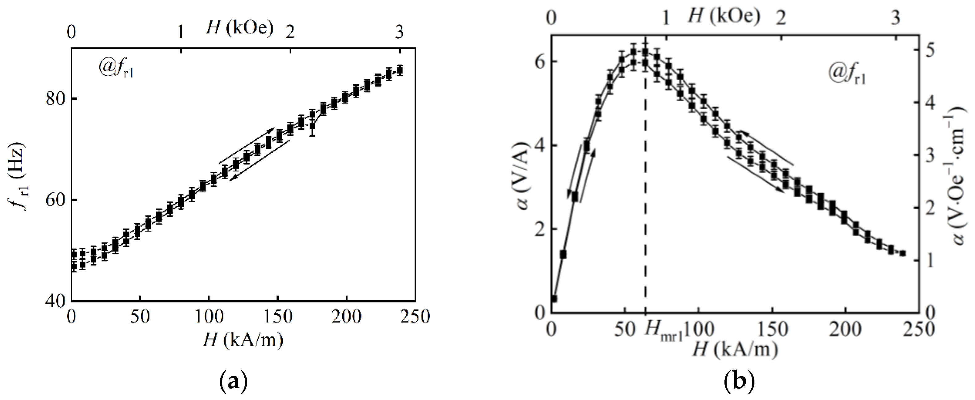
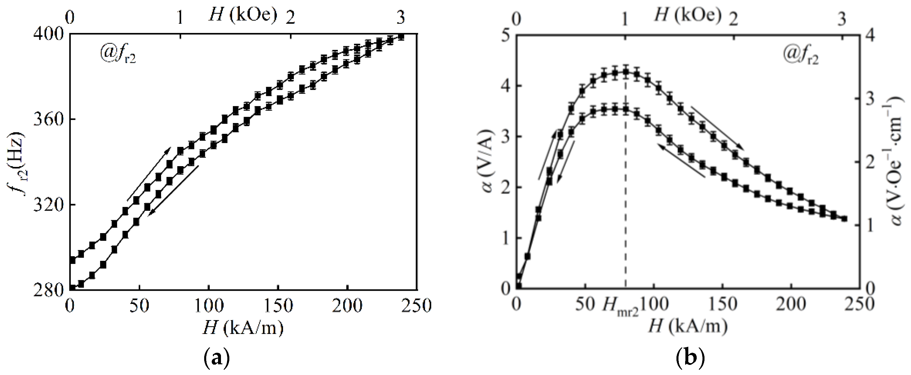
  • For three samples with thinner MAE layers, there was an optimum magnetic field where the magnetoelectric voltage coefficient at resonance frequencies fr1 and fr2 had a maximum. In the L–T-configuration, the mechanism of the resonance enhancement of the MAE voltage coefficient seemed to be the same as in conventional structures containing metallic FM layers.
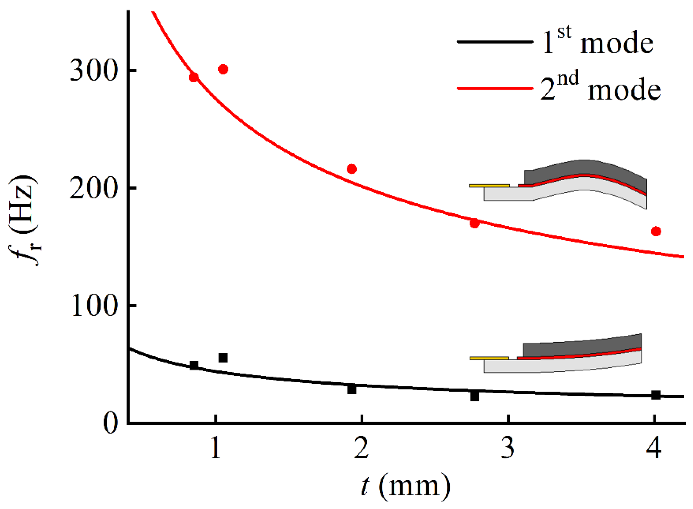
  • The softness of constitutive materials led to a significant reduction in the resonance frequency of bending oscillations in the absence of a magnetic field down to about 23 Hz.
  • The resonance frequencies of the MAE/PEP heterostructure increased with an increase in the bias magnetic field. The change of the resonance frequency of the lowest bending mode in the bias magnetic field of ≈240 kA/m could reach approximately 200%.
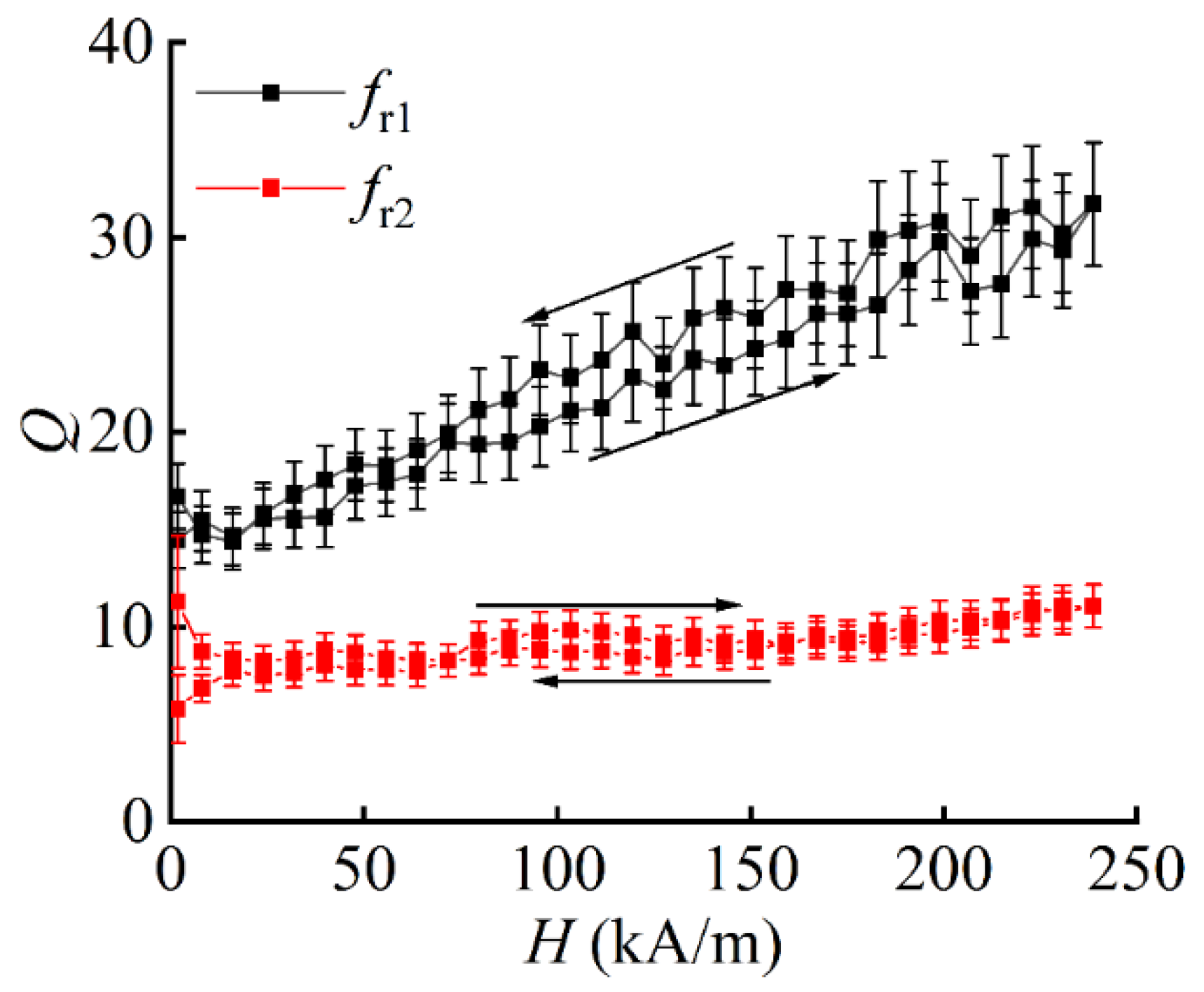
  • The hysteresis behavior of the ME voltage coefficient and the resonance frequency on the applied constant magnetic field was observed for the second lowest resonance frequency of bending oscillations.

Author Contributions

Conceptualization, M.S. and L.Y.F.; methodology, D.V.S., G.G. and I.A.B.; validation, D.V.S., L.Y.F. and M.S.; investigation, D.V.S. and V.O.B.; resources, I.A.B., G.G. and L.Y.F.; data curation, D.V.S. and L.Y.F.; writing—original draft preparation, M.S. and D.V.S.; writing—review and editing, M.S., D.V.S. and L.Y.F.; visualization, D.V.S.; supervision, L.Y.F. and M.S.; project administration, L.Y.F. and M.S.; funding acquisition, L.Y.F. and M.S. All authors have read and agreed to the published version of the manuscript.

Funding

This research was funded by the Russian Foundation of Basic Research, grant number 20-32-90-190, and the Deutsche Forschungsgemeinschaft (DFG, German Research Foundation), project number 466920132. I.A.B. was supported by The State Conference of Women and Equality Officers at Bavarian Universities (LaKoF Bayern).

Institutional Review Board Statement

Not applicable.

Data Availability Statement

The data that support the findings of this study are available from the corresponding author, D.V.S., upon reasonable request.

Acknowledgments

The measurements were partially performed using the equipment of the Joint Center for Collective Use of RTU MIREA.

Conflicts of Interest

The authors declare no conflict of interest.

References

  1. Srinivasan, G. Magnetoelectric Composites. Annu. Rev. Mater. Res. 2010, 40, 153–178. [Google Scholar] [CrossRef]
  2. Alameh, Z.; Yang, S.; Deng, Q.; Sharma, P. Emergent Magnetoelectricity in Soft Materials, Instability, and Wireless Energy Harvesting. Soft Matter 2018, 14, 5856–5868. [Google Scholar] [CrossRef]
  3. Bukharaev, A.A.; Zvezdin, A.K.; Pyatakov, A.P.; Fetisov, Y.K. Straintronics: A New Trend in Micro- and Nanoelectronics and Materials Science. Phys.-Uspekhi 2018, 61, 1175. [Google Scholar] [CrossRef]
  4. Kulkarni, A.; Meurisch, K.; Teliban, I.; Jahns, R.; Strunskus, T.; Piorra, A.; Knöchel, R.; Faupel, F. Giant Magnetoelectric Effect at Low Frequencies in Polymer-Based Thin Film Composites. Appl. Phys. Lett. 2014, 104, 022904. [Google Scholar] [CrossRef]
  5. Yu, Z.; Chu, Z.; Yang, J.; Pourhosseini Asl, M.J.; Li, Z.; Dong, S. Enhancing weak magnetic field MME coupling in NdFeB magnet/piezoelectric composite cantilevers with stress concentration effect. Appl. Phys. Lett. 2021, 118, 132902. [Google Scholar] [CrossRef]
  6. Zhai, J.; Dong, S.; Xing, Z.; Li, J.; Viehland, D. Giant Magnetoelectric Effect in Metglas/Polyvinylidene-Fluoride Laminates. Appl. Phys. Lett. 2006, 89, 083507. [Google Scholar] [CrossRef] [Green Version]
  7. Greve, H.; Woltermann, E.; Jahns, R.; Marauska, S.; Wagner, B.; Knöchel, R.; Wuttig, M.; Quandt, E. Low Damping Resonant Magnetoelectric Sensors. Appl. Phys. Lett. 2010, 97, 152503. [Google Scholar] [CrossRef]
  8. Jahns, R.; Piorra, A.; Lage, E.; Kirchhof, C.; Meyners, D.; Gugat, J.L.; Krantz, M.; Gerken, M.; Knöchel, R.; Quandt, E. Giant Magnetoelectric Effect in Thin-Film Composites. J. Am. Ceram. Soc. 2013, 96, 1673–1681. [Google Scholar] [CrossRef]
  9. Kirchhof, C.; Krantz, M.; Teliban, I.; Jahns, R.; Marauska, S.; Wagner, B.; Knöchel, R.; Gerken, M.; Meyners, D.; Quandt, E. Giant Magnetoelectric Effect in Vacuum. Appl. Phys. Lett. 2013, 102, 232905. [Google Scholar] [CrossRef]
  10. Fetisov, L.Y.; Chashin, D.V.; Saveliev, D.V.; Afanas’ev, M.S.; Simonov-Emel’yanov, I.D.; Vopson, M.M.; Fetisov, Y.K. Magnetoelectric Direct and Converse Resonance Effects in a Flexible Ferromagnetic-Piezoelectric Polymer Structure. J. Magn. Magn. Mater. 2019, 485, 251–256. [Google Scholar] [CrossRef]
  11. Wang, Y.; Gray, D.; Berry, D.; Gao, J.; Li, M.; Li, J.; Viehland, D. An Extremely Low Equivalent Magnetic Noise Magnetoelectric Sensor. Adv. Mater. 2011, 23, 4111–4114. [Google Scholar] [CrossRef]
  12. Reermann, J.; Durdaut, P.; Salzer, S.; Demming, T.; Piorra, A.; Quandt, E.; Frey, N.; Höft, M.; Schmidt, G. Evaluation of Magnetoelectric Sensor Systems for Cardiological Applications. Measurement 2018, 116, 230–238. [Google Scholar] [CrossRef]
  13. Petrov, V.M.; Srinivasan, G.; Bichurin, M.I.; Galkina, T.A. Theory of Magnetoelectric Effect for Bending Modes in Magnetostrictive-Piezoelectric Bilayers. J. Appl. Phys. 2009, 105, 063911. [Google Scholar] [CrossRef]
  14. Feng, J.; Xuan, S.; Ding, L.; Gong, X. Magnetoactive Elastomer/PVDF Composite Film Based Magnetically Controllable Actuator with Real-Time Deformation Feedback Property. Compos. Part A Appl. Sci. Manuf. 2017, 103, 25–34. [Google Scholar] [CrossRef]
  15. Makarova, L.A.; Rodionova, V.V.; Alekhina, Y.A.; Rusakova, T.S.; Omelyanchik, A.S.; Perov, N.S. New Multiferroic Composite Materials Consisting of Ferromagnetic, Ferroelectric, and Polymer Components. IEEE Trans. Magn. 2017, 53, 1–7. [Google Scholar] [CrossRef]
  16. Makarova, L.A.; Alekhina, Y.A.; Omelyanchik, A.S.; Peddis, D.; Spiridonov, V.V.; Rodionova, V.V.; Perov, N.S. Magnetorheological Foams for Multiferroic Applications. J. Magn. Magn. Mater. 2019, 485, 413–418. [Google Scholar] [CrossRef]
  17. Tan, K.; Wen, X.; Deng, Q.; Shen, S.; Liu, L.; Sharma, P. Soft Rubber as a Magnetoelectric Material—Generating Electricity from the Remote Action of a Magnetic Field. Mater. Today 2021, 43, 8–16. [Google Scholar] [CrossRef]
  18. Elhajjar, R.; Law, C.-T.; Pegoretti, A. Magnetostrictive Polymer Composites: Recent Advances in Materials, Structures and Properties. Prog. Mater. Sci. 2018, 97, 204–229. [Google Scholar] [CrossRef]
  19. Makarova, L.A.; Alekhina, Y.A.; Isaev, D.A.; Khairullin, M.F.; Perov, N.S. Tunable Layered Composites Based on Magnetoactive Elastomers and Piezopolymer for Sensors and Energy Harvesting Devices. J. Phys. Appl. Phys. 2020, 54, 015003. [Google Scholar] [CrossRef]
  20. Glavan, G.; Belyaeva, I.A.; Ruwisch, K.; Wollschläger, J.; Shamonin, M. Magnetoelectric Response of Laminated Cantilevers Comprising a Magnetoactive Elastomer and a Piezoelectric Polymer, in Pulsed Uniform Magnetic Fields. Sensors 2021, 21, 6390. [Google Scholar] [CrossRef]
  21. Vopson, M.M.; Fetisov, Y.K.; Caruntu, G.; Srinivasan, G. Measurement Techniques of the Magneto-Electric Coupling in Multiferroics. Materials 2017, 10, 963. [Google Scholar] [CrossRef]
  22. Newnham, R.E.; Skinner, D.P.; Cross, L.E. Connectivity and Piezoelectric-Pyroelectric Composites. Mater. Res. Bull. 1978, 13, 525–536. [Google Scholar] [CrossRef]
  23. LDT with Crimps Vibration Sensor/Switch. Available online: https://eu.mouser.com/datasheet/2/418/5/NG_DS_LDT_with_Crimps_A1-1130083.pdf (accessed on 11 August 2021).
  24. Becker, T.I.; Raikher, Y.L.; Stolbov, O.V.; Böhm, V.; Zimmermann, K. Magnetic Hybrid-Materials; De Gruyter: Berlin, Germany, 2021; Chapter 26; pp. 625–652. [Google Scholar]
  25. Zubarev, A.; Chirikov, D.; Borin, D.; Stepanov, G. Hysteresis of the Magnetic Properties of Soft Magnetic Gels. Soft Matter 2016, 12, 6473–6480. [Google Scholar] [CrossRef] [PubMed] [Green Version]
  26. Belyaeva, I.A.; Kramarenko, E.Y.; Shamonin, M. Magnetodielectric Effect in Magnetoactive Elastomers: Transient Response and Hysteresis. Polymer 2017, 127, 119–128. [Google Scholar] [CrossRef]
  27. Timoshenko, S. Vibration Problems in Engineering, Reprint ed.; Wolfenden Press: New York, NY, USA, 2007; ISBN 978-1-4067-7465-8. [Google Scholar]
  28. Sreenivasulu, G.; Qu, P.; Petrov, V.M.; Qu, H.; Srinivasan, G. Magneto-electric interactions at bending resonance in an asymmetric multiferroic composite: Theory and experiment on the influence of electrode position. J. Appl. Phys. 2015, 117, 174105. [Google Scholar] [CrossRef]
  29. Petrov, V.M.; Bichurin, M.I.; Srinivasan, G.; Laletin, V.M.; Petrov, R.V. Bending modes and magnetoelectric effects in asymmetric ferromagnetic-ferroelectric structure. Solid State Phenom. 2012, 190, 281–284. [Google Scholar] [CrossRef]
  30. Talleb, H.; Ren, Z. Finite element modeling of magnetoelectric laminate composites in considering nonlinear and load effects for energy harvesting. J. Alloys Compd. 2014, 615, 65–74. [Google Scholar] [CrossRef]
  31. Liu, Y.X.; Wan, J.G.; Liu, J.M.; Nan, C.W. Effect of magnetic bias field on magnetoelectric coupling in magnetoelectric composites. J. Appl. Phys. 2003, 94, 5118–5122. [Google Scholar] [CrossRef] [Green Version]
  32. Martins, P.; Lanceros-Méndez, S. Polymer-based magnetoelectric materials: To be or not to be. Appl. Mater. Today 2019, 15, 558–561. [Google Scholar] [CrossRef] [Green Version]
  33. Liang, X.; Matyushov, A.; Hayes, P.; Schell, L.; Dong, C.; Chen, H.; He, Y.; Will-Cole, A.; Quandt, E.; Martins, P.; et al. Roadmap on magnetoelectric materials and devices. IEEE Trans. Magn. 2021, 57, 400157. [Google Scholar] [CrossRef]
  34. Pereira, N.; Lima, A.C.; Lanceros-Mendez, S.; Martins, P. Magnetoelectrics: Three Centuries of Research Heading Towards the 4.0 Industrial Revolution. Materials 2020, 13, 4033. [Google Scholar] [CrossRef]
  35. Feng, M.; Wang, J.-J.; Hu, J.-M.; Wang, J.; Ma, J.; Li, H.-B.; Shen, Y.; Lin, Y.-H.; Chen, L.-Q.; Nan, C.-W. Optimizing direct magnetoelectric coupling in Pb(Zr,Ti)O3/Ni multiferroic film heterostructures. Appl. Phys. Lett. 2015, 106, 072901. [Google Scholar] [CrossRef] [Green Version]
  36. Chashin, D.V.; Fetisov, Y.K.; Tafintseva, E.V.; Srinivasan, G. Magnetoelctric effects in layered samples of lead zirconate titanate and nickel films. Solid State Commun. 2008, 148, 55–58. [Google Scholar] [CrossRef]
  37. Palneedi, H.; Annapureddy, V.; Priya, S.; Ryu, J. Status and Perspectives of Multiferroic Magnetoelectric Composite Materials and Applications. Actuators 2016, 5, 9. [Google Scholar] [CrossRef] [Green Version]
  38. Jing, W.; Fang, F. A flexible multiferroic composite with high self-biased magnetoelectric coupling. Compos. Sci. Technol. 2017, 153, 145–150. [Google Scholar] [CrossRef]
  39. Belouadah, R.; Guyomar, D.; Guiffard, B.; Zhang, J.W. Phase switching phenomenon in magnetoelectric laminate polymer composites: Experiments and modeling. Phys. B Condens. Matter 2011, 406, 2821–2826. [Google Scholar] [CrossRef]
  40. Yang, S.C.; Park, C.S.; Cho, K.H.; Priya, S. Self-biased magnetoelectric response in three-phase laminates. J. Appl. Phys. 2010, 108, 093706. [Google Scholar] [CrossRef] [Green Version]
  41. Guyomar, D.; Matei, D.; Guiffard, B.; Le, Q.; Belouadah, R. Magnetoelectricity in polyurethane films loaded with different magnetic particles. Mater. Lett. 2009, 63, 611–613. [Google Scholar] [CrossRef]
  42. Mu, X.; Zhang, H.; Zhang, C.; Yang, S.; Xu, J.; Huang, Y.; Xu, J.; Zhang, Y.; Li, Q.; Wang, X.; et al. Poly(vinylidene fluoride-trifluoroethylene)/cobalt ferrite composite films with a self-biased magnetoelectric effect for flexible AC magnetic sensors. J. Mater. Sci. 2021, 56, 9728–9740. [Google Scholar] [CrossRef]
  43. Omelyanchik, A.; Antipova, V.; Gritsenko, C.; Kolesnikova, V.; Murzin, D.; Han, Y.; Turutin, A.V.; Kubasov, I.V.; Kislyuk, A.M.; Ilina, T.S.; et al. Boosting Magnetoelectric Effect in Polymer-Based Nanocomposites. Nanomaterials 2021, 11, 1154. [Google Scholar] [CrossRef]
  44. Martins, P.; Kolen’ko, Y.V.; Rivas, J.; Lanceros-Méndez, S. Tailored magnetic and magnetoelectric responses of polymer-based composites. ACS Appl. Mater. Interfaces 2015, 7, 15017–15022. [Google Scholar] [CrossRef] [PubMed] [Green Version]
  45. Reis, S.; Silva, M.; Castro, N.; Correia, V.M.G.; Gutiérrez, J.; Lasheras, A.; Lanceros-Méndez, S.; Martins, P. Optimized anisotropic magnetoelectric response of Fe61.6Co16.4Si10.8B11.2/PVDF/Fe61.6Co16.4Si10.8B11.2laminates for AC/DC magnetic field sensing. Smart Mater. Struct. 2016, 25, 55050. [Google Scholar] [CrossRef]
  46. Silva, M.; Reis, S.; Lehmann, C.; Martins, P.; Lanceros-Méndez, S.; Lasheras, A.; Gutierrez, J.; Barandiaran, J. Optimization of the magnetoelectric response of poly(vinylidene fluoride)/Epoxy/Vitrovac laminates. ACS Appl. Mater. Interfaces 2013, 5, 10912–10919. [Google Scholar] [CrossRef] [PubMed]
  47. Fetisov, L.Y.; Baraban, I.A.; Fetisov, Y.K.; Burdin, D.A.; Vopson, M.M. Nonlinear magnetoelectric effects in flexible composite ferromagnetic—Piezopolymer structures. J. Magn. Magn. Mater. 2017, 441, 628–634. [Google Scholar] [CrossRef] [Green Version]
  48. Lu, S.G.; Jin, J.Z.; Zhou, X.; Fang, Z.; Wang, Q.; Zhang, Q.M. Large magnetoelectric coupling coefficient in poly (vinylidene fluoride-hexafluoropropylene)/Metglas laminates. J. Appl. Phys. 2011, 110, 104103. [Google Scholar] [CrossRef]
  49. Wang, J.J.; Hsu, T.H.; Yeh, C.N.; Tsai, J.W.; Su, Y.C. Piezoelectric polydimethylsiloxane films for MEMS transducers. J. Micromech. Microeng. 2011, 22, 015013. [Google Scholar] [CrossRef]
  50. Kachroudi, A.; Basrour, S.; Rufer, L.; Sylvestre, A.; Jomni, F. Micro-structured PDMS piezoelectric enhancement through charging conditions. Smart Mater. Struct. 2016, 25, 105027. [Google Scholar] [CrossRef]
Figure 1. Sketch of the fabricated ME heterostructure and the orientation of the applied magnetic field.
Applsci 12 02102 g001
Figure 2. Schematic diagram of the experimental setup: 1—electromagnet’s poles; 2—excitation coil; 3—magnetic field sensor. Directions of the magnetization M in the MAE layer and the polarization P in the PEP are shown.
Applsci 12 02102 g002
Figure 3. Frequency dependences of the ME voltage coefficient α for sample S1 at different bias magnetic fields for the following curves: 1—H = 1.8; 2—31.8; 3—55.7; 4—79.6; 5—175; 6—240 kA/m. The inset shows part of the frequency dependence of the ME voltage coefficient for sample S2 at bias magnetic field H = 175 kA/m. The amplitude of the AC magnetic field was h = 0.22 kA/m.
Applsci 12 02102 g003
Figure 4. Field dependences of the quality factor Q at resonance frequency fr1 and fr2 obtained for sample S1. Arrows denote the direction of field change.
Applsci 12 02102 g004
Figure 5. Dependences of the ME voltage u of sample S1 on the amplitude h of the AC magnetic field for different resonance frequencies. H = Hmr1 = 55.7 kA/m for fr1 and H = Hmr2 = 79.6 kA/m for fr2. R2 stands for the determination coefficient of the linear regression.
Applsci 12 02102 g005
Figure 6. Field dependences of (a) the fundamental bending resonance frequency fr1 and (b) the corresponding ME voltage coefficient α at resonance for sample 1. h = 0.22 A/m. Arrows denote the direction of field change.
Applsci 12 02102 g006
Figure 7. Field dependences of the (a) second bending resonance frequency fr2 and (b) the corresponding ME voltage coefficient α at resonance for sample S1. h = 0.22 A/m. Arrows denote the direction of field change.
Applsci 12 02102 g007
Figure 8. Comparison of obtained ME voltage coefficients at resonant frequencies fr1 and fr2 for different samples.
Applsci 12 02102 g008
Figure 9. Comparison of theoretical (continuous lines) and experimental (dots) dependences of the resonance frequencies fr1 and fr2 on the thickness of the MAE layer. The inset schematically shows the bending modes.
Applsci 12 02102 g009
Table 1. Measured parameters of all samples.
Parameter/SampleS1S2S3S4S5
Thickness of MAE layer tMAE, mm0.851.051.932.774.01
Resonance frequency
fr1(H = 0), Hz
49.255.528.522.723.9
Quality factor at fr1 in optimum magnetic field Hmr11924191416 *
Maximum α @ fr1, V/A6.236.887.853.361.81 *
(fr1(Hmax) − fr1(0))/fr1(0), %7460.4145.6215.9164.4
Resonance frequency
fr2(H = 0), Hz
294301216170 **163 ***
Quality factor at fr2 in optimum magnetic field Hmr2916869
Maximum α @ fr2, V/A4.273.663.011.69 **2.38 **
(fr2(Hmax) − fr2(0))/fr2(0), %35.737.271.89082.8 ***
* This value was determined for the first local maximum of α at H = 32 kA/m. ** This value was determined for the maximum magnetic field H = 240 kA/m. *** The second bending resonance in sample S5 was observable in the DC magnetic field H > 8 kA/m. These values referred to H = 8 kA/m as an initial magnetic field.
Publisher’s Note: MDPI stays neutral with regard to jurisdictional claims in published maps and institutional affiliations.

