
Experimental Investigation on Inner- and Inter-Strip Reinforcements for 3D Printed Concrete via Automatic Staple Inserting Technique


Abstract
:1. Introduction
2. Materials and Devices
2.1. Printable Material
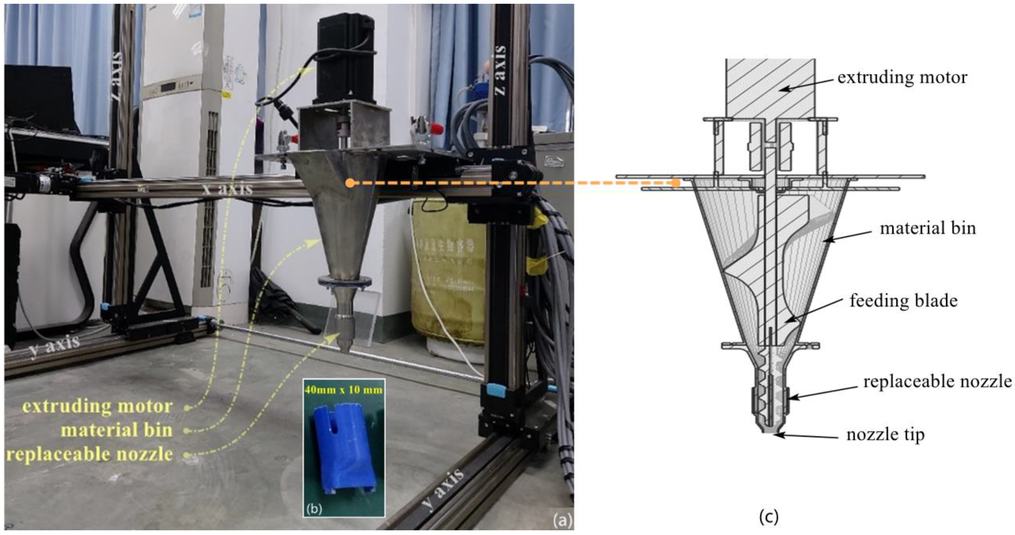
2.2. Printing Device
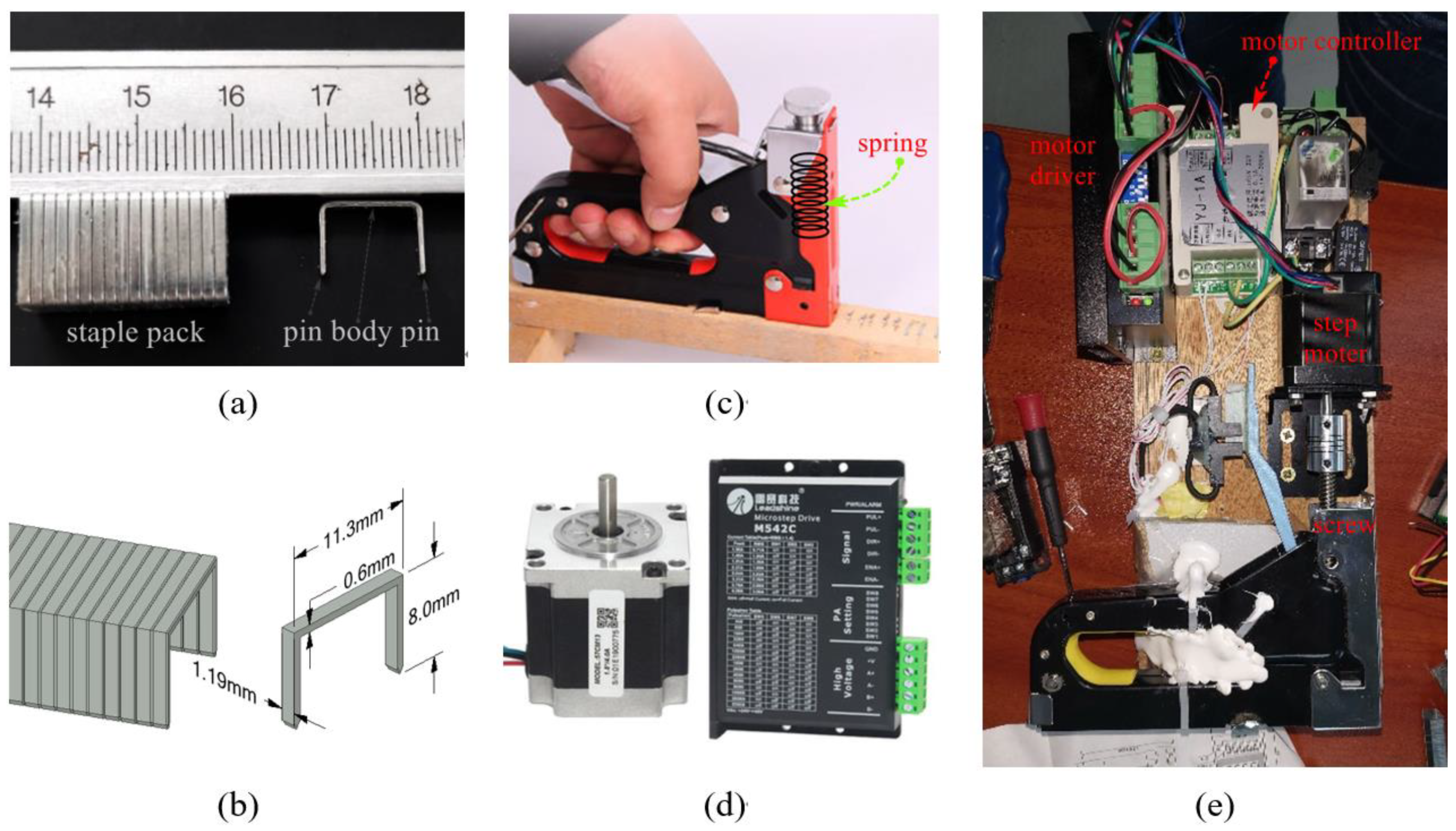
2.3. Staples and Inserting Apparatus
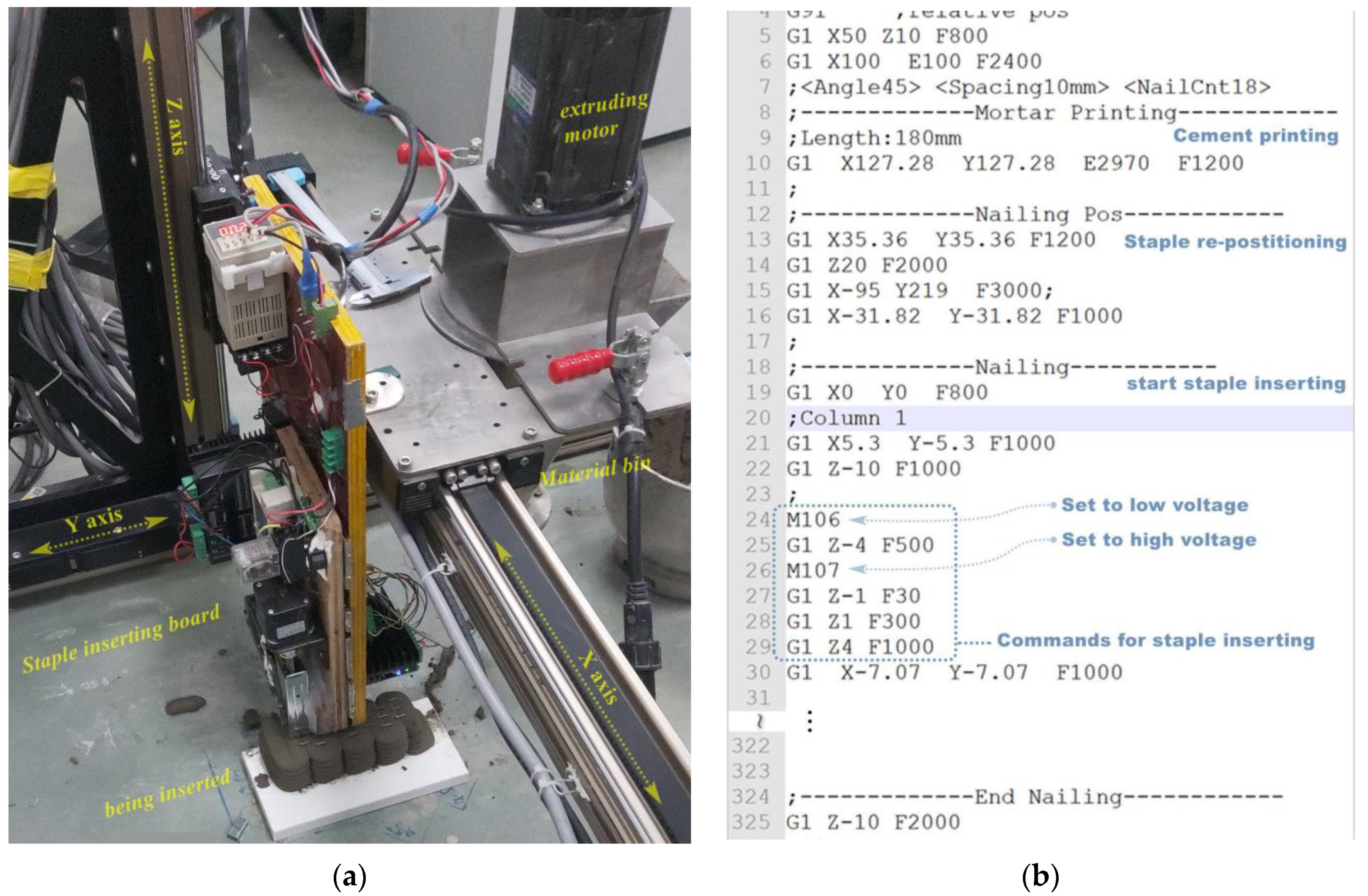
2.4. The 3DCP-SIT System
3. Experimental Progress
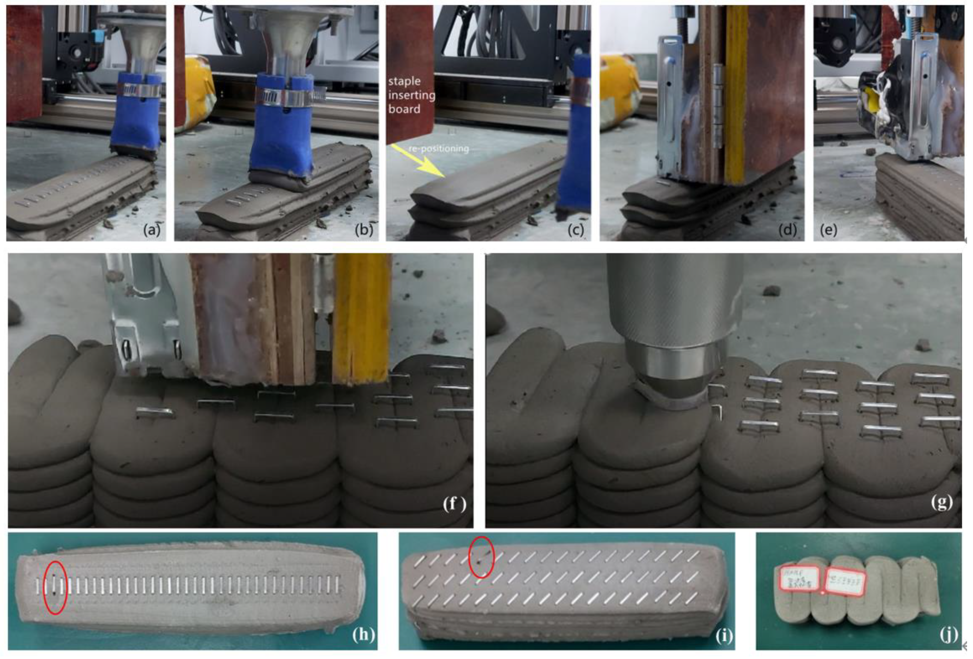
3.1. Fabrication Process
3.2. Fabricating Measurements
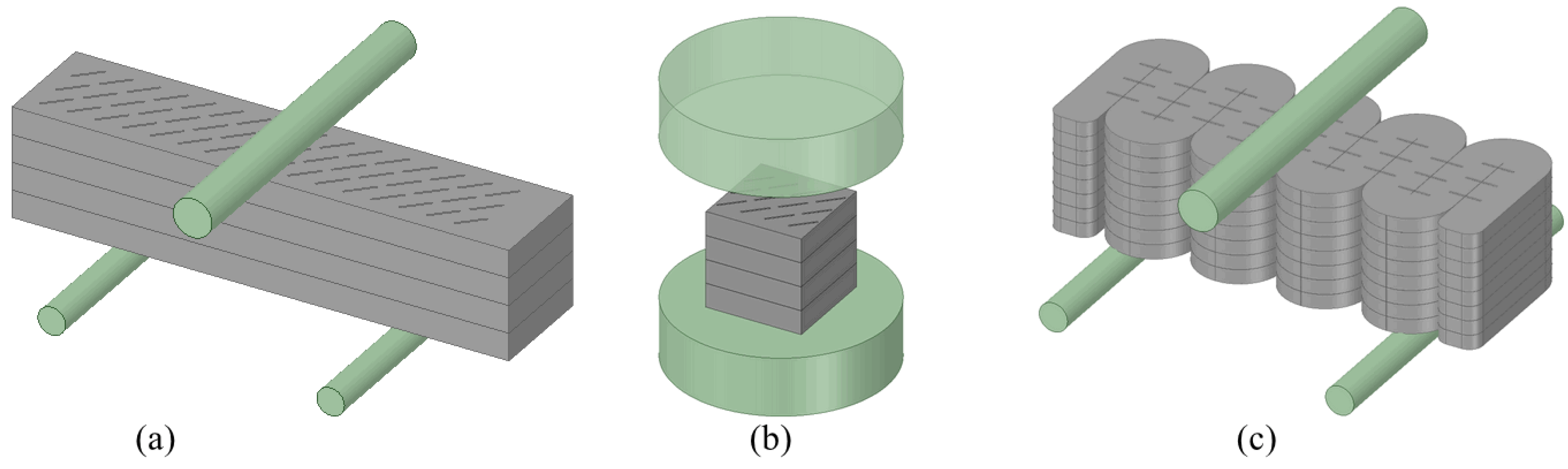
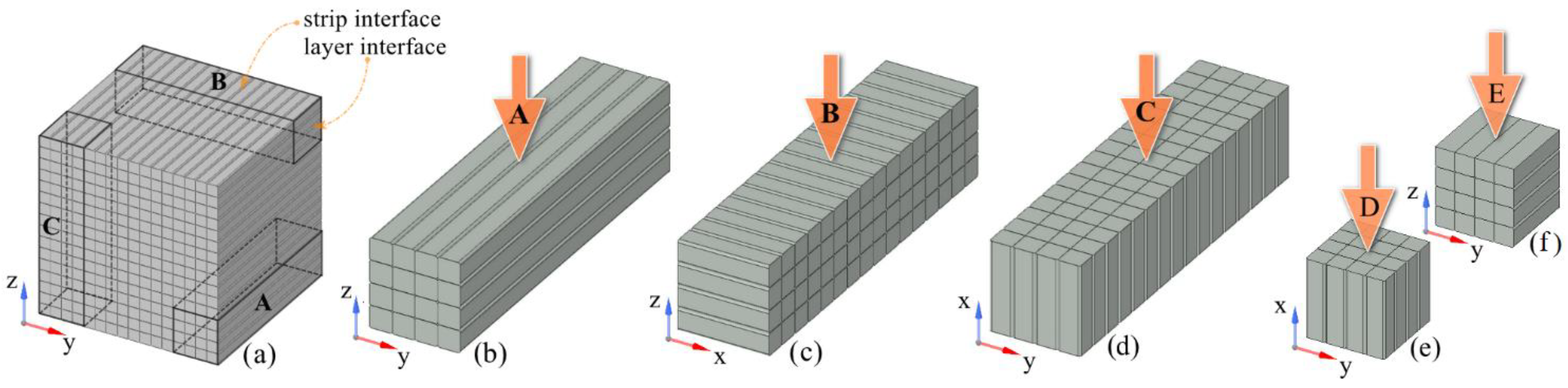
3.3. Tests on Mechanical Properties
4. Results and Discussion
4.1. Fabrication Using 3DCP-SIT
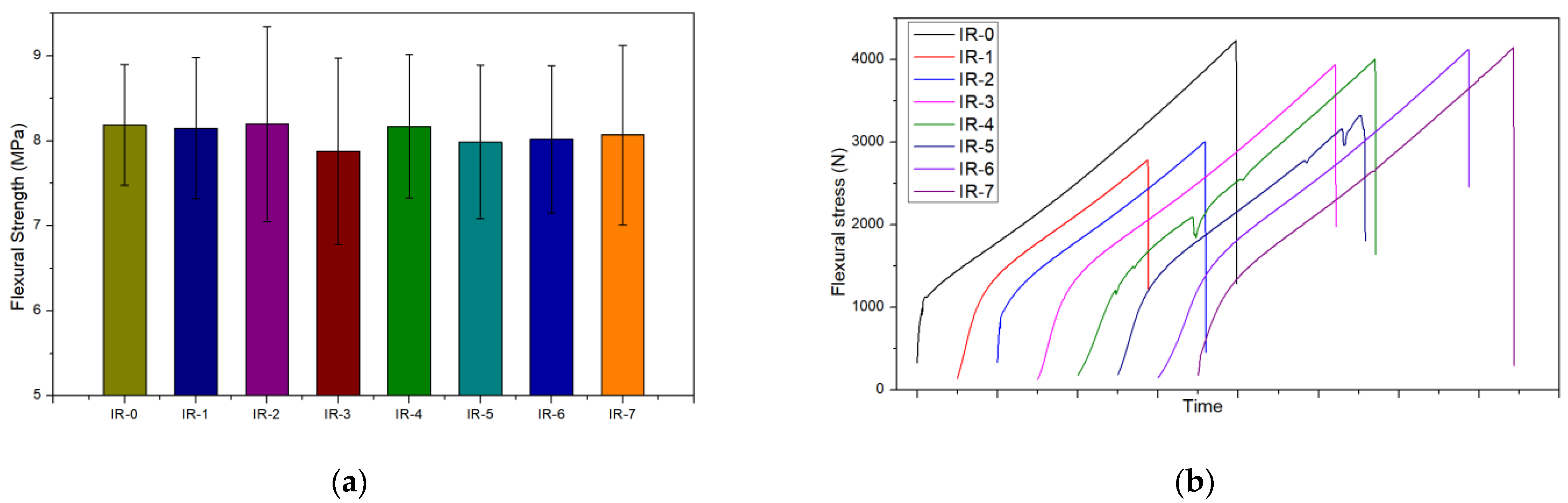
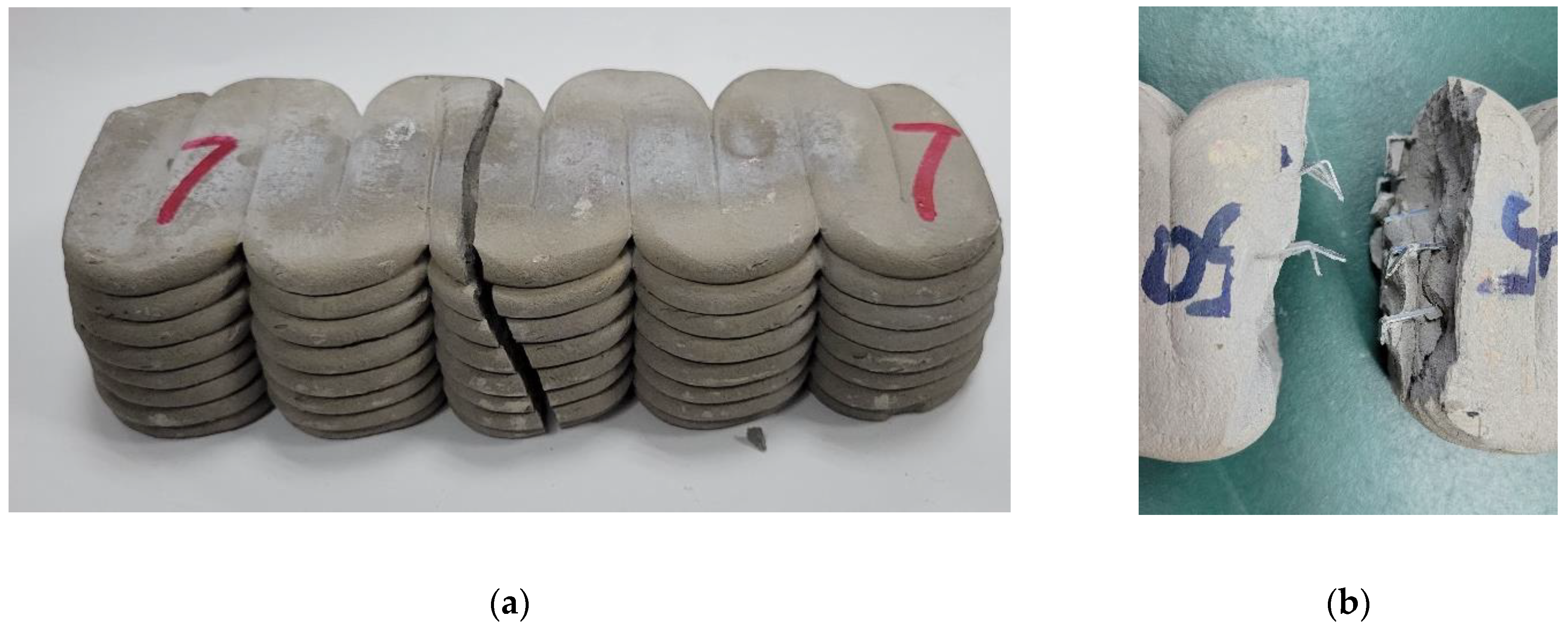
4.2. Flexural Tests of IR- Samples
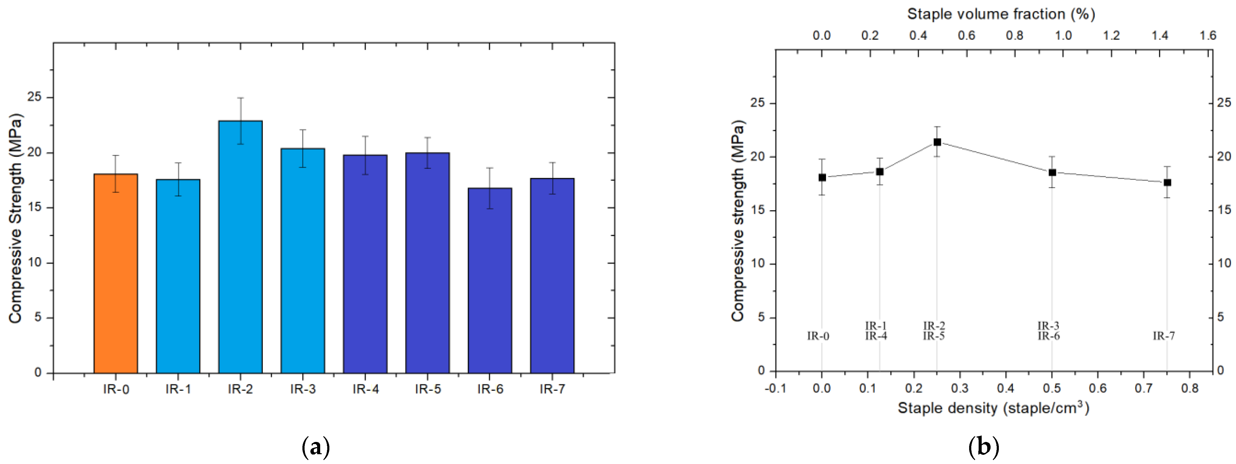
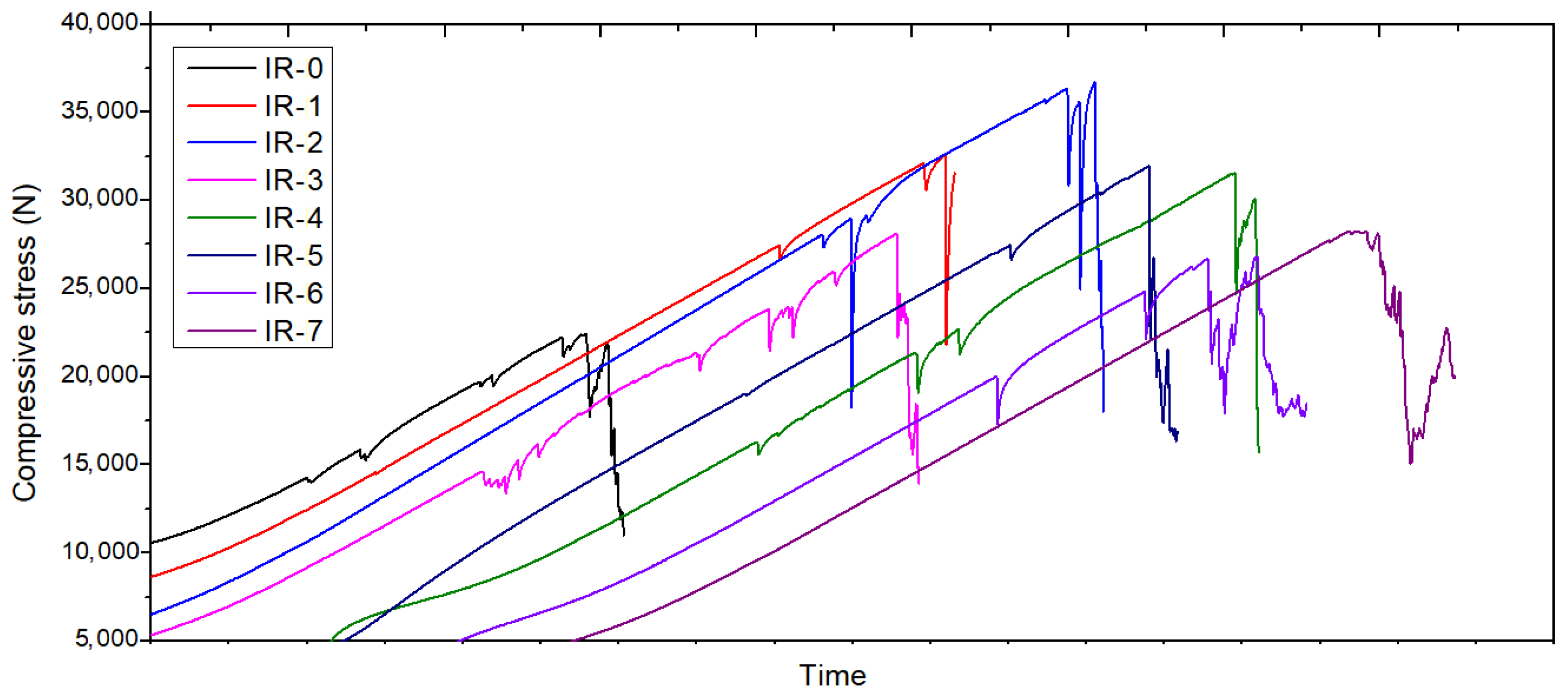
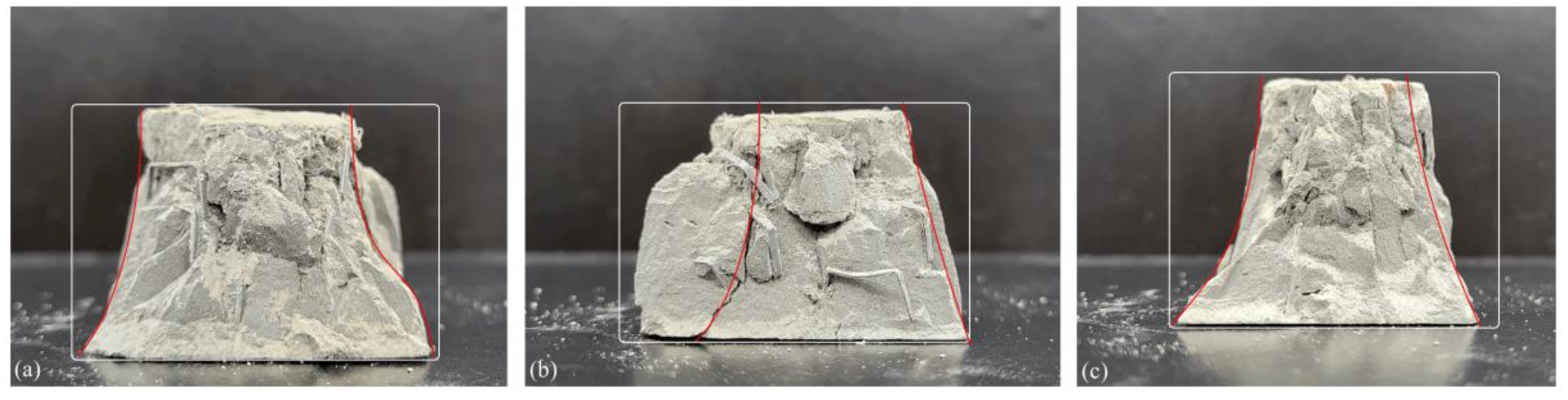
4.3. Compressive Tests on IR- Samples
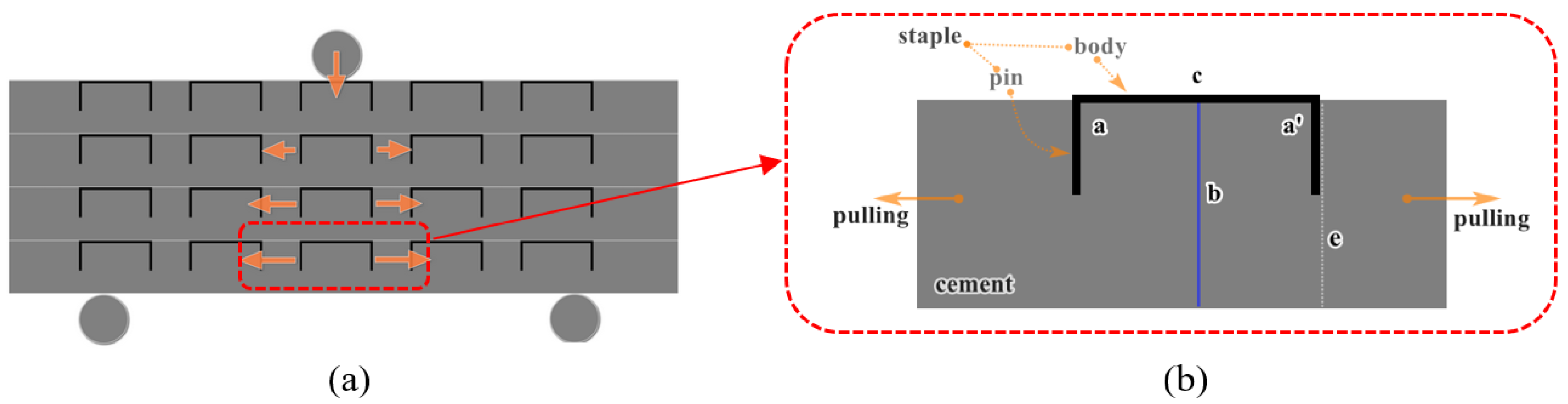
4.4. Flexural Tests on IL- Samples
4.5. Mechanical Analysis
4.6. Fabricating Parameters
4.7. The 3DCP-SIT Technique
5. Conclusions
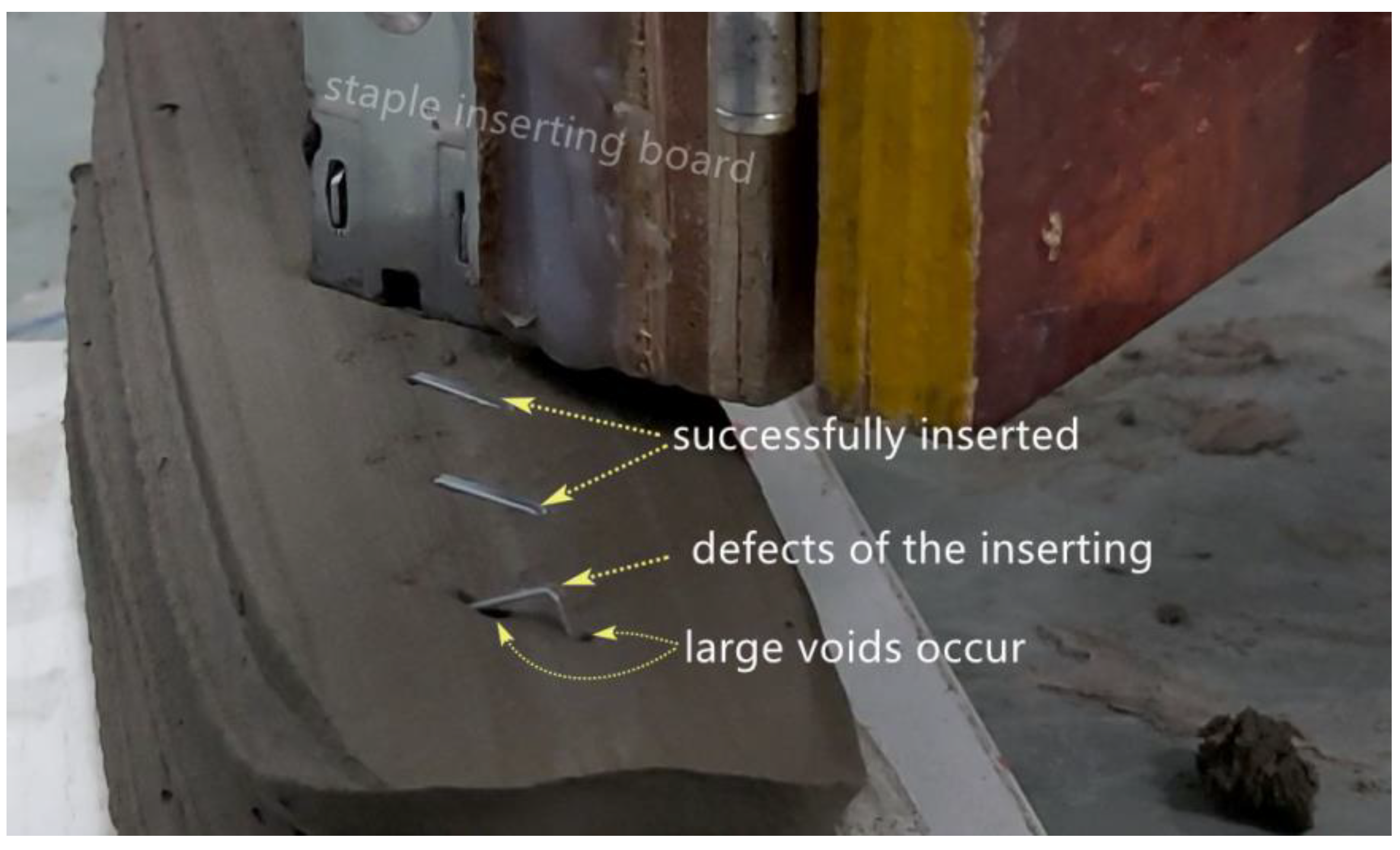
- The staples were distributed and aligned as designed entirely using automatic equipment with a success ratio higher than 98%.
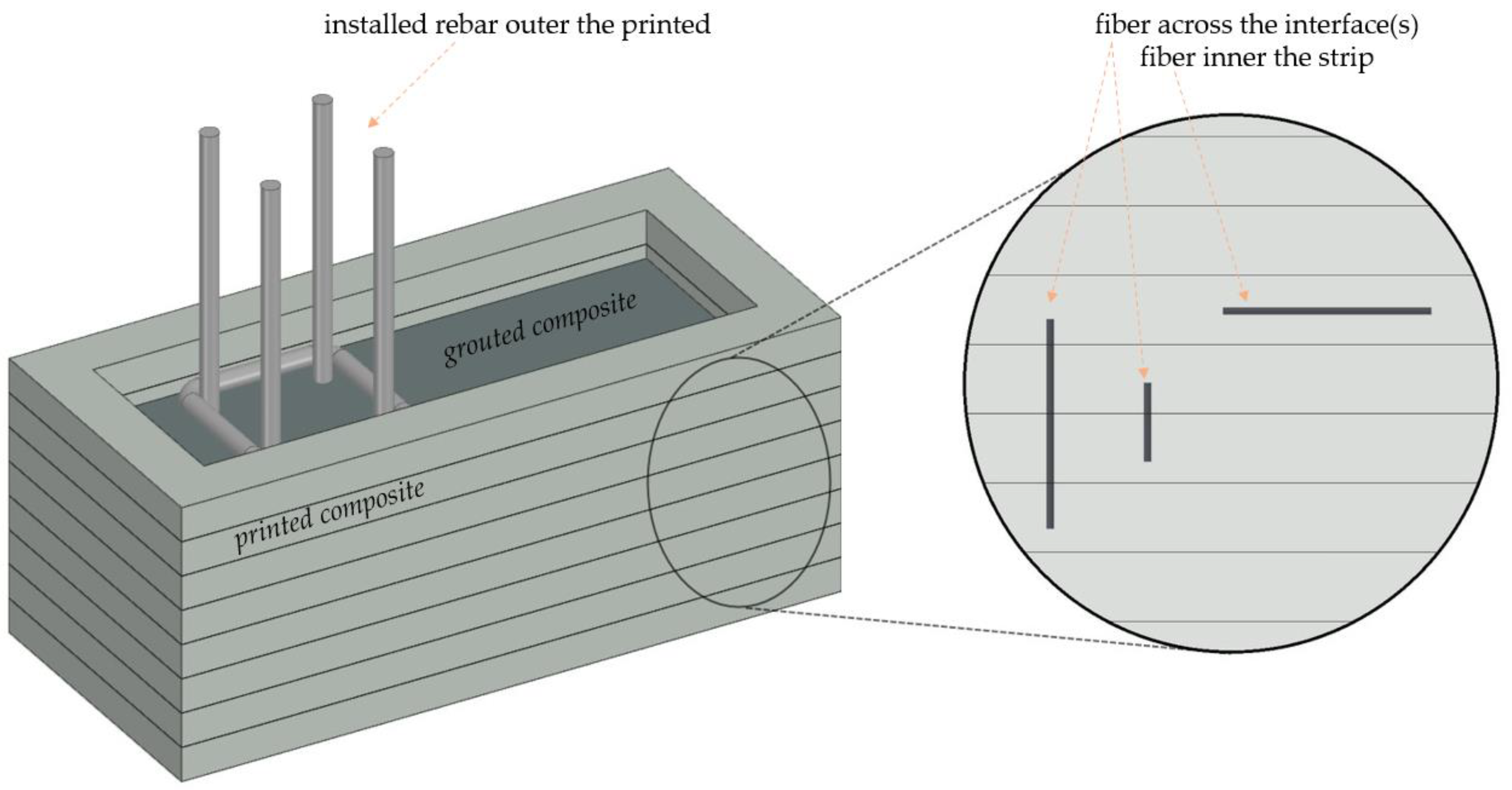
- The inner-inserted staples (in IR- samples) showed no noticeable improvement to the flexural strengths because the inserted staples were distributed without overlap and worked alone to lock the composite within the staple pins. They improved the compressive strengths by an average of 5%. Samples with a staple density of 0.25 staples per cubic centimeter had the maximum improvement in compressive strength, which was 25%.
- The inter-inserted staples (in IL- samples) improved the flexural stress by 46–120% by locking the strips. Further analysis showed that the printing parameters can affect the mechanical properties and the improving rate.
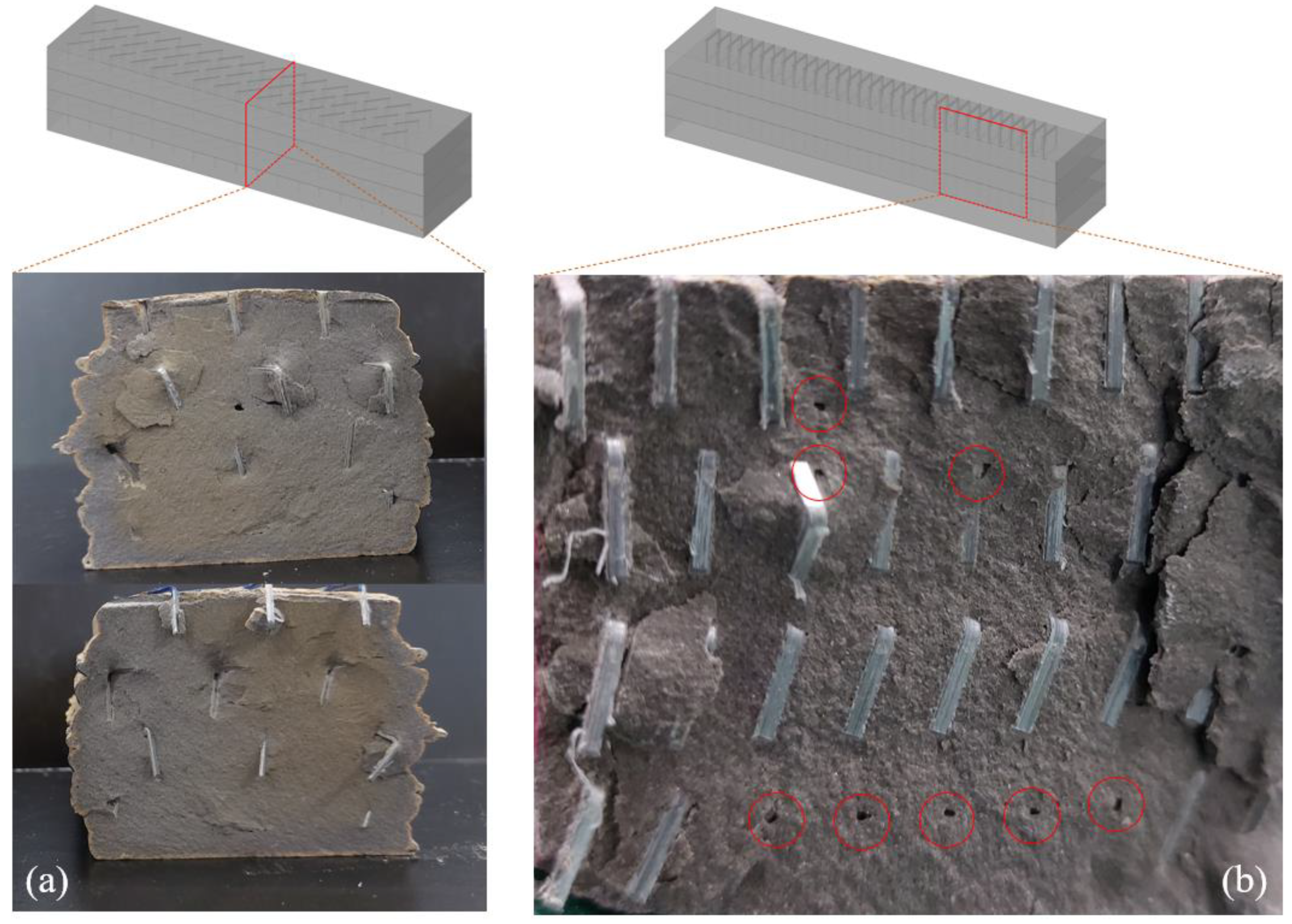
- The staple inserting operation introduced voids as defects in the composite properties, and a high staple density decreased the overall mechanical properties. Thus, the inserting technique should be further studied to minimize the voids.
- Future studies should be conducted on reinforcements with high staple density, via an upgraded printing-inserting system which can print cement mortar and insert staples at the same time.
Author Contributions
Funding
Institutional Review Board Statement
Informed Consent Statement
Data Availability Statement
Acknowledgments
Conflicts of Interest
References
- Lo Giudice, A.; Ronsivalle, V.; Grippaudo, C.; Lucchese, A.; Muraglie, S.; Lagravère, M.O.; Isola, G. One Step before 3D Printing—Evaluation of Imaging Software Accuracy for 3-Dimensional Analysis of the Mandible: A Comparative Study Using a Surface-to-Surface Matching Technique. Materials 2020, 13, 2798. [Google Scholar] [CrossRef] [PubMed]
- Matarese, G.; Isola, G.; Ramaglia, L.; Dalessandri, D.; Lucchese, A.; Fabiano, F.; Cordasco, G. Periodontal biotype: Characteristic, prevalence and dimensions related to dental malocclusion. Minerva Stomatol. 2016, 65, 231–238. [Google Scholar] [PubMed]
- De Schutter, G.; Lesage, K.; Mechtcherine, V.; Nerella, V.N.; Habert, G.; Juan, I.A. Vision of 3D printing with concrete—Technical, economic and environmental potentials. Cem. Concr. Res. 2018, 112, 25–36. [Google Scholar] [CrossRef]
- Ghaffar, S.H.; Mullett, P. Commentary: 3D printing set to transform the construction industry. Proc. Inst. Civ. Eng. Struct. Build. 2018, 171, 737–738. [Google Scholar] [CrossRef]
- Pegna, J. Exploratory investigation of solid freeform construction. Autom. Constr. 1997, 5, 427–437. [Google Scholar] [CrossRef]
- Khoshnevis, B. Automated construction by contour crafting—Related robotics and information technologies. Autom. Constr. 2004, 13, 5–19. [Google Scholar] [CrossRef]
- Sikora, P.; Chougan, M.; Cuevas, K.; Liebscher, M.; Mechtcherine, V.; Ghaffar, S.H.; Liard, M.; Lootens, D.; Krivenko, P.; Sanytsky, M.; et al. The effects of nano- and micro-sized additives on 3D printable cementitious and alkali-activated composites: A review. Appl. Nanosci. 2021, 1–19. [Google Scholar] [CrossRef]
- Chougan, M.; Ghaffar, S.H.; Jahanzat, M.; Albar, A.; Mujaddedi, N.; Swash, R. The influence of nano-additives in strengthening mechanical performance of 3D printed multi-binder geopolymer composites. Constr. Build. Mater. 2020, 250, 118928. [Google Scholar] [CrossRef]
- Chougan, M.; Ghaffar, S.H.; Sikora, P.; Chung, S.-Y.; Rucinska, T.; Stephan, D.; Albar, A.; Swash, M.R. Investigation of additive incorporation on rheological, microstructural and mechanical properties of 3D printable alkali-activated materials. Mater. Des. 2021, 202, 109574. [Google Scholar] [CrossRef]
- Sanjayan, J.G.; Nematollahi, B.; Xia, M.; Marchment, T. Effect of surface moisture on inter-layer strength of 3D printed concrete. Constr. Build. Mater. 2018, 172, 468–475. [Google Scholar] [CrossRef]
- Van Der Putten, J.; Deprez, M.; Cnudde, V.; De Schutter, G.; Van Tittelboom, K. Microstructural Characterization of 3D Printed Cementitious Materials. Materials 2019, 12, 2993. [Google Scholar] [CrossRef] [PubMed] [Green Version]
- Van Der Putten, J.; De Schutter, G.; Van Tittelboom, K. Surface modification as a technique to improve inter-layer bonding strength in 3D printed cementitious materials. RILEM Tech. Lett. 2019, 4, 33–38. [Google Scholar] [CrossRef]
- Li, Z.; Wang, L.; Ma, G. Mechanical improvement of continuous steel microcable reinforced geopolymer composites for 3D printing subjected to different loading conditions. Compos. Part B Eng. 2020, 187, 107796. [Google Scholar] [CrossRef]
- Ogura, H.; Nerella, V.N.; Mechtcherine, V. Developing and Testing of Strain-Hardening Cement-Based Composites (SHCC) in the Context of 3D-Printing. Materials 2018, 11, 1375. [Google Scholar] [CrossRef] [Green Version]
- Ma, G.; Li, Z.; Wang, L.; Wang, F.; Sanjayan, J. Mechanical anisotropy of aligned fiber reinforced composite for extrusion-based 3D printing. Constr. Build. Mater. 2019, 202, 770–783. [Google Scholar] [CrossRef]
- Farina, I.; Fabbrocino, F.; Carpentieri, G.; Modano, M.; Amendola, A.; Goodall, R.; Feo, L.; Fraternali, F. On the reinforcement of cement mortars through 3D printed polymeric and metallic fibers. Compos. Part B Eng. 2016, 90, 76–85. [Google Scholar] [CrossRef]
- Hambach, M.; Volkmer, D. Properties of 3D-printed fiber-reinforced Portland cement paste. Cem. Concr. Compos. 2017, 79, 62–70. [Google Scholar] [CrossRef]
- Figueiredo, S.C.; Rodriguez, C.R.; Ahmed, Z.Y.; Bos, D.; Xu, Y.; Salet, T.M.; Copuroglu, O.; Schlangen, E.; Bos, F.P. An approach to develop printable strain hardening cementitious composites. Mater. Des. 2019, 169, 107651. [Google Scholar] [CrossRef]
- Sonebi, M.; Amziane, S.; Perrot, A. Mechanical Behavior of 3D Printed Cement Materials. In 3D Printing of Concrete; ISTE: London, UK, 2019; pp. 101–124. [Google Scholar] [CrossRef]
- Rubio, M.; Sonebi, M.; Amzian, S. Fresh and rheological properties of 3D printing bio-cement-based materials. In Proceedings of the 2nd ICBBM (PRO 119), Clermont-Ferrand, France, 21–23 June 2017. [Google Scholar] [CrossRef]
- Panda, B.; Paul, S.C.; Tan, M.J. Anisotropic mechanical performance of 3D printed fiber reinforced sustainable construction material. Mater. Lett. 2017, 209, 146–149. [Google Scholar] [CrossRef]
- Fallon, J.J.; McKnight, S.H.; Bortner, M.J. Highly loaded fiber filled polymers for material extrusion: A review of current understanding. Addit. Manuf. 2019, 30, 100810. [Google Scholar] [CrossRef]
- Le, T.T.; Austin, S.A.; Lim, S.; Buswell, R.A.; Law, R.; Gibb, A.G.F.; Thorpe, T. Hardened properties of high-performance printing concrete. Cem. Concr. Res. 2012, 42, 558–666. [Google Scholar] [CrossRef] [Green Version]
- Bos, F.P.; Ahmed, Z.Y.; Jutinov, E.R.; Salet, T.A.M. Experimental Exploration of Metal Cable as Reinforcement in 3D Printed Concrete. Materials 2017, 10, 1314. [Google Scholar] [CrossRef] [PubMed] [Green Version]
- Bos, F.P.; Ahmed, Z.Y.; Wolfs, R.J.M.; Salet, T.A.M. 3D Printing Concrete with Reinforcement. In High Tech Concrete: Where Technology and Engineering Meet; Springer: Cham, Switzerland, 2017; pp. 2484–2493. [Google Scholar] [CrossRef]
- Salet, T.A.M.; Ahmed, Z.Y.; Bos, F.P.; Laagland, H.L.M. Design of a 3D printed concrete bridge by testing. Virtual Phys. Prototyp. 2018, 13, 222–236. [Google Scholar] [CrossRef] [Green Version]
- Lim, J.H.; Panda, B.; Pham, Q.-C. Improving flexural characteristics of 3D printed geopolymer composites with in-process steel cable reinforcement. Constr. Build. Mater. 2018, 178, 32–41. [Google Scholar] [CrossRef]
- Bos, F.; Wolfs, R.; Ahmed, Z.; Salet, T. Large Scale Testing of Digitally Fabricated Concrete (DFC) Elements. In Historic Mortars; Springer Science and Business Media LLC: Dordrecht, The Netherlands, 2018; pp. 129–147. [Google Scholar]
- Baz, B.; Aouad, G.; Leblond, P.; Al-Mansouri, O.; D’Hondt, M.; Remond, S. Mechanical assessment of concrete—Steel bonding in 3D printed elements. Constr. Build. Mater. 2020, 256, 119457. [Google Scholar] [CrossRef]
- Baz, B.; Aouad, G.; Remond, S. Effect of the printing method and mortar’s workability on pull-out strength of 3D printed elements. Constr. Build. Mater. 2020, 230, 117002. [Google Scholar] [CrossRef]
- Perrot, A.; Jacquet, Y.; Rangeard, D.; Courteille, E.; Sonebi, M. Nailing of Layers: A Promising Way to Reinforce Concrete 3D Printing Structures. Materials 2020, 13, 1518. [Google Scholar] [CrossRef] [Green Version]
- Liu, M.; Zhang, Q.; Tan, Z.; Wang, L.; Li, Z.; Ma, G. Investigation of steel wire mesh reinforcement method for 3D concrete printing. Arch. Civ. Mech. Eng. 2021, 21, 1–18. [Google Scholar] [CrossRef]
- Sun, X.; Gao, C.; Wang, H. Bond performance between BFRP bars and 3D printed concrete. Constr. Build. Mater. 2021, 269, 121325. [Google Scholar] [CrossRef]
- Wang, L.; Ma, G.; Liu, T.; Buswell, R.; Li, Z. Interlayer reinforcement of 3D printed concrete by the in-process deposition of U-nails. Cem. Concr. Res. 2021, 148, 106535. [Google Scholar] [CrossRef]
- Asprone, D.; Auricchio, F.; Menna, C.; Mercuri, V. 3D printing of reinforced concrete elements: Technology and design approach. Constr. Build. Mater. 2018, 165, 218–231. [Google Scholar] [CrossRef]
- Katzer, J.; Szatkiewicz, T. Properties of concrete elements with 3-D printed formworks which substitute steel reinforcement. Constr. Build. Mater. 2019, 210, 157–161. [Google Scholar] [CrossRef]
- Salazar, B.; Aghdasi, P.; Williams, I.D.; Ostertag, C.P.; Taylor, H.K. Polymer lattice-reinforcement for enhancing ductility of concrete. Mater. Des. 2020, 196, 109184. [Google Scholar] [CrossRef]
- Xu, Y.; Šavija, B. Development of strain hardening cementitious composite (SHCC) reinforced with 3D printed polymeric reinforcement: Mechanical properties. Compos. Part B Eng. 2019, 174, 107011. [Google Scholar] [CrossRef]
- Marchment, T.; Sanjayan, J. Bond properties of reinforcing bar penetrations in 3D concrete printing. Autom. Constr. 2020, 120, 103394. [Google Scholar] [CrossRef]
- Chen, Y.; Figueiredo, S.C.; Li, Z.; Chang, Z.; Jansen, K.; Çopuroğlu, O.; Schlangen, E. Improving printability of limestone-calcined clay-based cementitious materials by using viscosity-modifying admixture. Cem. Concr. Res. 2020, 132, 106040. [Google Scholar] [CrossRef]
- Chen, M.; Li, L.; Zheng, Y.; Zhao, P.; Lu, L.; Cheng, X. Rheological and mechanical properties of admixtures modified 3D printing sulphoaluminate cementitious materials. Constr. Build. Mater. 2018, 189, 601–611. [Google Scholar] [CrossRef]
- Matthäus, C.; Kofler, N.; Kränkel, T.; Weger, D.; Gehlen, C. Interlayer Reinforcement Combined with Fiber Reinforcement for Extruded Lightweight Mortar Elements. Materials 2020, 13, 4778. [Google Scholar] [CrossRef]
- Marchment, T.; Sanjayan, J. Mesh reinforcing method for 3D Concrete Printing. Autom. Constr. 2020, 109, 102992. [Google Scholar] [CrossRef]
- Bos, F.P.; Bosco, E.; Salet, T.A.M. Ductility of 3D printed concrete reinforced with short straight steel fibers. Virtual Phys. Prototyp. 2019, 14, 160–174. [Google Scholar] [CrossRef]
- Pham, L.; Tran, P.; Sanjayan, J. Steel fibres reinforced 3D printed concrete: Influence of fibre sizes on mechanical performance. Constr. Build. Mater. 2020, 250, 118785. [Google Scholar] [CrossRef]
- Hambach, M.; Möller, H.; Neumann, T.; Volkmer, D. Portland cement paste with aligned carbon fibers exhibiting exceptionally high flexural strength (> 100 MPa). Cem. Concr. Res. 2016, 89, 80–86. [Google Scholar] [CrossRef]
- Sun, J.; Aslani, F.; Lu, J.; Wang, L.; Huang, Y.; Ma, G. Fibre-reinforced lightweight engineered cementitious composites for 3D concrete printing. Ceram. Int. 2021, 47, 27107–27121. [Google Scholar] [CrossRef]
- Meurer, M.; Classen, M. Mechanical Properties of Hardened 3D Printed Concretes and Mortars—Development of a Consistent Experimental Characterization Strategy. Materials 2021, 14, 752. [Google Scholar] [CrossRef] [PubMed]
- Ye, J.; Cui, C.; Yu, J.; Yu, K.; Xiao, J. Fresh and anisotropic-mechanical properties of 3D printable ultra-high ductile concrete with crumb rubber. Compos. Part B Eng. 2021, 211, 108639. [Google Scholar] [CrossRef]
- Bester, F.; Heever, M.V.D.; Kruger, J.; Cho, S.; van Zijl, G. Steel Fiber Links in 3D Printed Concrete; Springer Science and Business Media LLC: Cham, Switzerland, 2020; pp. 398–406. [Google Scholar]
- Babafemi, A.; Kolawole, J.; Miah, J.; Paul, S.; Panda, B. A Concise Review on Interlayer Bond Strength in 3D Concrete Printing. Sustainability 2021, 13, 7137. [Google Scholar] [CrossRef]
- Panda, B.; Paul, S.C.; Mohamed, N.A.N.; Tay, Y.W.D.; Tan, M.J. Measurement of tensile bond strength of 3D printed geopolymer mortar. Measurement 2018, 113, 108–116. [Google Scholar] [CrossRef]
- Bos, F.; Dezaire, S.; Ahmed, Z.; Hoekstra, A.; Salet, T. Bond of Reinforcement Cable in 3D Printed Concrete; Springer Science and Business Media LLC: Cham, Switzerland, 2020; pp. 584–600. [Google Scholar]
- Arigela, S.H.; Ch R, V.K. Investigation on Dual Nozzle Fused Deposition Modelling using Industrial Robot. Adv. Mater. Process. Technol. 2020, 1–19. [Google Scholar] [CrossRef]
- Reichenbach, S.; Preinstorfer, P.; Hammerl, M.; Kromoser, B. A review on embedded fibre-reinforced polymer reinforcement in structural concrete in Europe. Constr. Build. Mater. 2021, 307, 124946. [Google Scholar] [CrossRef]
- Bernard, E.; Thomas, A. Fibre reinforced sprayed concrete for ground support. Tunn. Undergr. Space Technol. 2020, 99, 103302. [Google Scholar] [CrossRef]


| OPC | GB | FA | SF | Water | HRWR | HPMC | PA | AR | TA | DFA |
|---|---|---|---|---|---|---|---|---|---|---|
| 2000 | 400 | 294 | 106 | 800 | 4 | 6 | 20 | 15 | 30 | 1 |
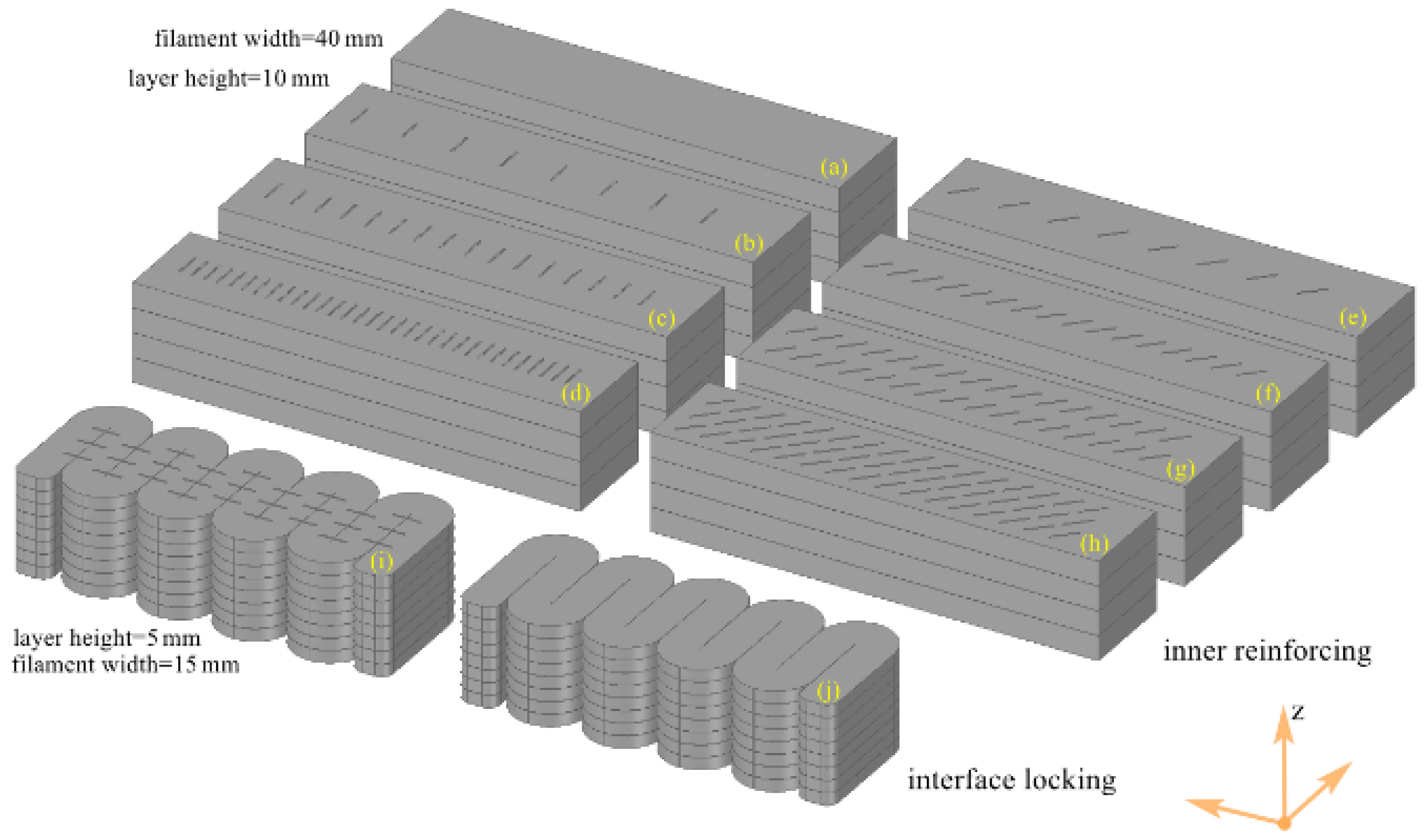
| Name | Figure 5 | Purpose and Nozzle | Filament | Staple | |||||
|---|---|---|---|---|---|---|---|---|---|
| Width | Height | Angle 1 | Spacing 2 | Column | Density 3 | V% 4 | |||
| IR-0 | (a) | Inner Reinforcing with Rectangle Nozzle | 40 | 10 | - | 0 | 0 | ||
| IR-1 | (b) | 90 90 90 | 20 | 1 | 0.125 | 0.24% | |||
| IR-2 | (c) | 10 | 1 | 0.250 | 0.48% | ||||
| IR-3 | (d) | 5 | 1 | 0.500 | 0.95% | ||||
| IR-4 | (e) | 45 | 20 | 1 | 0.125 | 0.24% | |||
| IR-5 | (f) | 45 | 10 | 1 | 0.250 | 0.48% | |||
| IR-6 | (g) | 45 | 10 | 2 | 0.500 | 0.95% | |||
| IR-7 | (h) | 45 | 10 | 3 | 0.750 | 1.43% | |||
| IL-0 | (i) | Interface Locking with Round Nozzle | 15 | 5 | - | ||||
| IL-1 | (j) | 90 | 10 | ||||||
| IL-2 | (i) | - | |||||||
| IL-3 | (j) | 90 | 10 | ||||||
Publisher’s Note: MDPI stays neutral with regard to jurisdictional claims in published maps and institutional affiliations. |
© 2022 by the authors. Licensee MDPI, Basel, Switzerland. This article is an open access article distributed under the terms and conditions of the Creative Commons Attribution (CC BY) license (https://creativecommons.org/licenses/by/4.0/).
Share and Cite
Cao, X.; Yu, S.; Cui, H. Experimental Investigation on Inner- and Inter-Strip Reinforcements for 3D Printed Concrete via Automatic Staple Inserting Technique. Appl. Sci. 2022, 12, 2099. https://doi.org/10.3390/app12042099
Cao X, Yu S, Cui H. Experimental Investigation on Inner- and Inter-Strip Reinforcements for 3D Printed Concrete via Automatic Staple Inserting Technique. Applied Sciences. 2022; 12(4):2099. https://doi.org/10.3390/app12042099
Chicago/Turabian StyleCao, Xiangpeng, Shiheng Yu, and Hongzhi Cui. 2022. "Experimental Investigation on Inner- and Inter-Strip Reinforcements for 3D Printed Concrete via Automatic Staple Inserting Technique" Applied Sciences 12, no. 4: 2099. https://doi.org/10.3390/app12042099