Article

Development of Passive Fire Protection Mortars

1
Department of Civil Engineering, University of Coimbra, ISISE, Rua Luís Reis Santos, 3030-790 Coimbra, Portugal
2
Department of Chemical Engineering, University of Coimbra, CIEPQPF, Rua Sílvio Lima, 3030-790 Coimbra, Portugal
*
Author to whom correspondence should be addressed.
Appl. Sci. 2022, 12(4), 2093; https://doi.org/10.3390/app12042093
Submission received: 23 December 2021 / Revised: 31 January 2022 / Accepted: 7 February 2022 / Published: 17 February 2022
(This article belongs to the Special Issue New Challenges in Civil Structure for Fire Response)

Abstract

:
During a fire event, the stability of steel structures may be compromised, and structural collapse may occur due to the loss of their mechanical resistance as the temperature increases. One of the solutions to reduce this problem is the protection with a coating using enhanced fire-resistant mortars. This paper reports a detailed experimental work aiming to develop gypsum and cement-based mortars for passive fire protection and evaluate their composition’s effect in the final thermal performance. Two types of specimens were tested: (i) small specimens composed of a mortar coating (10 mm thick) and one steel plate and (ii) square section short tubular steel columns with 20 mm of coating. The evaluation of the thermal protection was carried out by (a) measuring the thermal gradient between the exposed surface of the protected steel plate under high temperatures and the mortar-steel interface and (b) assessing the fire resistance of the short steel columns. It was concluded that the compositions with gypsum binder present better thermal insulation than the cementitious compositions. Additionally, the introduction of nano- and microparticles of silica still slightly improved the thermal insulation of the tested compositions.

1. Introduction

There is a growing interest in developing alternative and sustainable construction materials with enhanced properties. As metals are infinitely recyclable, this type of construction is part of a future of “green construction”, thus contributing to a sector of the economy with low environmental impact [1,2,3].
However, steel structures show some weaknesses, especially their structural behaviour when subjected to fire [4,5,6,7,8,9]. Due to the high thermal conductivity of the steel, the high section factor of the members, and the rapid degradation of the steel mechanical properties, with the increase of steel temperature, rapid change in the stiffness and mechanical resistance may be noticed in the structure. Its resistance and stability may be compromised, leading to the collapse of some elements or even of the entire structure [10,11,12,13,14,15].
The thermal protection of these structural elements is crucial. The fire protection of structures can be achieved by combining active and passive fire protection systems and management systems (smoke exhaust systems, communication and evacuation procedures, fire detection systems, and compartmentation [16]). Active fire protection can consist of systems or items such as fire extinguishers, standpipes, sprinkler systems, and fire blankets [17]. It is required that these systems have a quick response capacity in extinguishing or controlling the development of a fire in its initial phase [18]. However, implementing these systems has high installation and maintenance costs, and their results can have low functional reliability and unsatisfactory operational results [19].
In turn, when applying passive protection, it is almost sure that it will be operational during a fire event. Passive systems include the fire resistance of structural or nonstructural members of a building, such as columns, beams, walls, and ceilings. This purpose ensures adequate evacuation times, minimum safety conditions for firefighting and rescue operations and minimises property, economic, and life losses [20].
The most common method to protect a member from exposure to extreme temperatures is to apply insulation materials around the structural members. Insulation materials used as fire protection in structural steel members can be: board systems (gypsum board or calcium silicate), insulating blankets (ceramic, rock, and glass wool), spray systems, or intumescent coatings [21]. These materials should be cheaper than the steelwork, easy of application, safe (i.e., not be hazardous during the application and in service, or toxic in the event of fire), and should insulate and remain undamaged during the fire attack (with limited detachments and fractures during the required fire resistance) [22].
One solution that meets these protection requirements is the coating with enhanced fire-resistant mortars due to the introduction of nanosilica particles and thermally stable and porous aggregates [23]. With the emergence of nanomaterials (silica nanoparticles, titanium dioxide nanoparticles, alumina nanoparticles, and carbon nanotubes, etc.), their incorporation in pastes, mortars, and other cement-based materials has appeared as a possibility to improve their mechanical and thermal properties: higher durability, better resistance to corrosion and better fire resistance [24,25,26,27,28], with the silica nanoparticles being the most studied nanomaterial in cement [26]. However, little attention has been given to other properties, such as thermal conductivity at elevated temperatures [29].
When subjected to high temperatures, perlite and vermiculite have been incorporated in cement mortars to improve their thermal performance [30]. Perlite consists of a siliceous volcanic rock with 2% to 6% water combined. However, when small perlite grains are subjected to high temperatures (870 °C), they strongly increase their volume with numerous tiny, sealed air cells, like popcorn giving rise to lightweight expanded perlite. Lightweight expanded perlite has low thermal conductivity (0.04–0.06 W/mK), relatively high melting point (1260–1343 °C) and low density (loose: 50–400 kg/m3) [31]. These characteristics make perlite a material with excellent insulating properties.
Vermiculite consists of a micalike mineral containing a shiny flake (the phyllosilicate group). It is produced at ambient conditions from the weathering/hydrothermal alteration of phlogopite or biotite [30]. Similar to perlite, when vermiculite particles are subjected to high temperatures (from 650 to 950 °C), they expand, presenting a density of 80 to 120 kg/m3, a melting point between 1240 to 1430 °C and a thermal conductivity between 0.04 to 0.12 W/mK [32]. Moreover, due to their highly porous structure, these materials absorb moisture in varying degrees (depending on their type), which when combined with the low thermal conductivity, extends their durability during the fire.
Perlite may be a better supplement than vermiculite, not only due to its thermal conductivity but also to the high retraction effect of vermiculite [33]. As they are materials with good thermal properties, they can be used in the development of plaster or cement mortars as a passive fire protection solution in steel structures.
In addition to cement, plaster can also be used as a binder and combined with perlite and/or vermiculite to develop mortars for passive fire protection. Compared to cement, gypsum is much cheaper, easier to produce, and provides a more effective thermal barrier because it has a lower thermal conductivity than cement. It also contributes to the energy loss from fire due to its endothermic dehydration process [34,35].
Studies have shown that perlite–Portland cement and perlite–gypsum coatings are the most effective plasters as fire barriers and in retarding the conduction of high temperatures across their thickness among different kinds of coatings, such as traditional-cement plaster, vermiculite cement/gypsum-based mortar, intumescent coating, calcium silicate board, and LECA-cement plaster [36,37,38].
Therefore, this paper presents the development of different gypsum or cement-based mortars as passive fire protection materials, the evaluation of the influence of aggregate size, and the addition of silica micro- and nanoparticles on their thermal performance and assessment of fire resistance to the protected short steel columns.

2. Materials and Methods

2.1. Materials and Compositions

In a preliminary phase, several mortars based on cement or gypsum were developed, with different dosages of raw materials, according to the state of the art as presented in the introduction of this paper (Table 1). The following materials were used in the compositions of the mortars: commercial passive protection solutions 1 (IGN) and 2 (VER), Portland cement CEM II/B-L 32.5 (PC), Isidac 40 refractory cement (IRC), Topeca M40 refractory cement (TRC), Eletroland refractory cement (ERC), gypsum powder (GP), expanded vermiculite with dimensions between 0.5 and 3 mm (EV), expanded perlite with dimensions between 1 and 5 mm (EP), polypropylene fibers with an average diameter of 31 μm and an average length of 6 mm (PP), silica sand with dimensions between 0.01 and 2.00 mm (SS), expanded clay with dimensions between 0.01 and 2.00 mm (EC), silica microparticles with an average diameter of 1000 nm (MS), silica nanoparticles with an average diameter of 200 nm (NS), and water (W). Silica micro- and nanoparticles were synthesised in the laboratory, according to the procedure described by Vaz-Ramos et al. [15].
Testing two commercial passive protection solutions tested, it was possible to identify the commercial solution that provided one of the best thermal insulation results, which came to be considered as the reference mortar (CM). From the preliminary tests phase, four different mortars were selected (DCM, DGMP, DGMV, and DRCM) from forty different mortars developed with greater thermal insulation capacity than that provided by the reference mortar. As can be seen in Table 2, the DCM was made with Portland cement, vermiculite and polypropylene fibers, the DGMP was prepared gypsum and perlite, the DGMV was made of gypsum and vermiculite and the DRCM was prepared with refractory cement, perlite, and vermiculite.
To analyze the influence of expanded perlite and expanded vermiculite grain size on the thermal performance of laboratory developed mortars, two different grinding methods were used: Los Angeles (LA) and Industrial Mill (IM). The first method was carried out using the Los Angeles method, which fragmented the aggregate by abrasion and shock using steel balls. The particle size of these raw materials was assessed using a particle size analysis (specification LNEC E 195-1966), and it was observed that their size ranged from 0.075 to 0.85 mm. The second method was carried out using an industrial mill, which by the friction of the aggregate with the drum significantly reduced the size of its particles compared to the LA method. The particle size analysis identified a particle size ranging from 0.025 to 0.40 mm. Finally, different dosages of silica micro and nanoparticles were added and tested in DCM, DGMP, DGMV, and DRCM to assess their influence on the thermal insulation of the respective mortars, as described in the following section of the paper.

2.2. Experimental Program

The experimental program included two different types of tests, depending on the type of specimens: steel plate (SP) (Table 3) and square section short steel columns (SSC) (Table 4). The experimental program of tests on SP included five different mortar (CM, DCM, DGMP, DGMV, and DRCM), and 45 specimens were produced. Each set of three specimens used in their thermal tests was used to obtain better reliability of results.
Table 3 presents the experimental program defined to evaluate the influence of the size of the aggregates and the addition of silica micro- and nanoparticles on the thermal performance of the developed mortars. The percentage of silica micro- and nanoparticles were the same and equal to 0.5% in weight of binder for each one. All specimens were exposed to high temperatures on one side up to 900 °C. Additionally, the experimental program of tests carried out on 12 SSC under fire conditions included three different fire protection mortars (CM, DCM, and DGMP). DGMV and others new ones will make part of another future experimental campaign, in which different aggregates/additives will be studied.

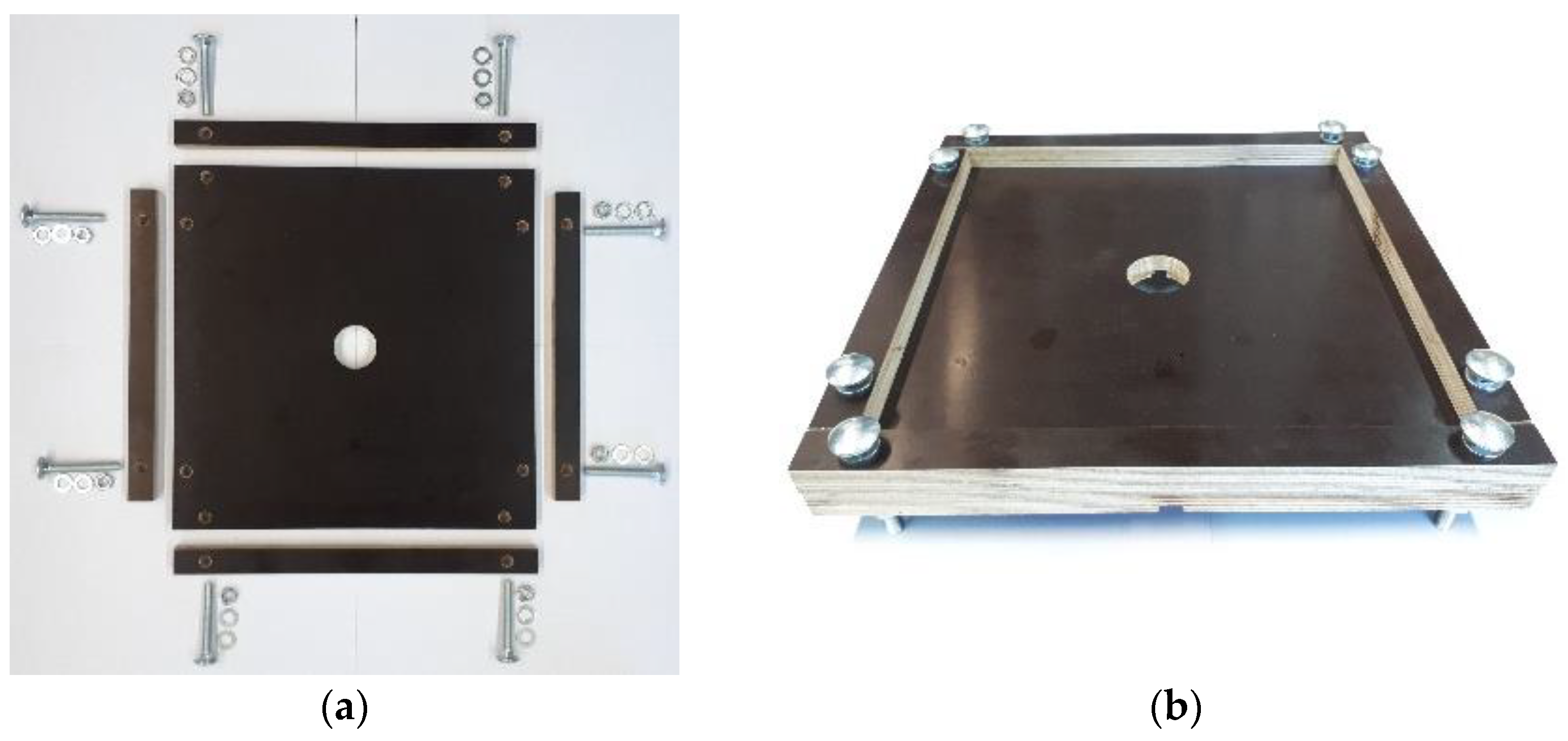
2.3. Preparation of the Specimens

The manufacturing process, shape, and dimensions of the SP and moulds were defined to measure the thermal gradient generated between the inner surface of the steel plate exposed to high temperatures and the exposed surface of the fire protection mortar. Thus, a suitable mould was designed and manufactured for these tests (Figure 1).
This mould assigns the desired geometric shape to the specimen, was easy to transport and clean, was reusable for many experimental tests, and was easy to assemble and disassemble when concreting and removing the specimen. During the fabrication of mortars, a balance accurate to 0.1 g, a graduated beaker, Hobart N50 mixer with 5 L of capacity and a stainless-steel lab spatula were used. The procedure adopted in the fabrication of mortars was as follows:
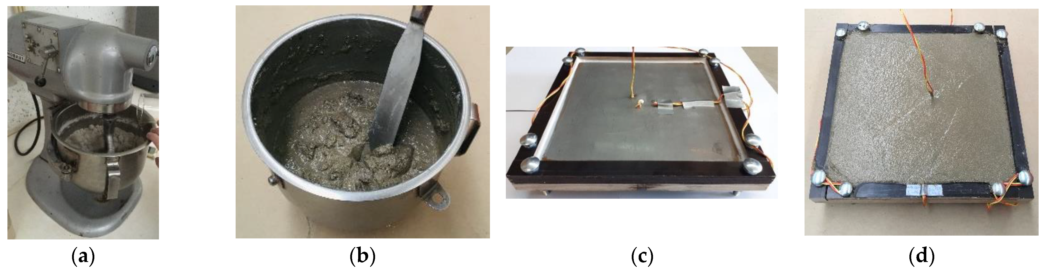
  • The raw materials were weighed and placed inside the mixer container.
  • Then, the mixer was put into operation for 5 min at a slow speed (136 rotations per minute). At the same time, the corresponding amount of water was added, with a constant flow rate to guarantee the homogeneous addition of water in the whole mortar.
  • After this procedure, the mortar was manually kneaded with a spatula to remove parts of the mortar that were on the walls of the container and thus homogenize the mixture, then returning the container to the mixer for another 2 min.
  • The mortar was placed inside the mould (Figure 2).
In the production of mortars, the same procedure was followed to ensure that the different properties of the mortars were only dependent on their composition. To minimize possible effects that temperature and humidity might have on the properties of each mortar composition, all mixtures of each composition were manufactured on the same day and placed in a room with controlled environmental conditions. It is well known that the moisture content greatly influences the fire behavior of mortars at elevated temperatures [39,40], in the same way as in the concretes.
About 48 h after casting the SP in the moulds described above, they were demoulded and placed in the curing process (Figure 3a) for 28 days in the laboratory environment with controlled temperature (25 °C) and a relative humidity (RH) of 55%. The specimens were tested with 6 months of age.
The specimens comprised a S355 steel plate with a square section of 250 mm of edge and a thickness of 5 mm; and 10 mm thick fire protection mortar on one side of the steel plate (Figure 3b). The temperature measurement in the SP was carried out by placing 4 type K thermocouples. The thermocouples were placed at different depths across the specimen (Figure 4).
With this distribution of thermocouples, it was possible to determine the thermal gradient between the surface of the mortar exposed to high temperatures (ESMHT—thermocouple 3) and the unexposed surface (USMHT—thermocouple 2), as well as the temperature on the inner surface of the steel plate (ISSP—thermocouple 1) and its external surface (ESSP—thermocouple 4). In Figure 5, it is possible to identify the thermocouples on the specimen following Figure 4.
Concerning the SSCs tests, specimens were defined by a hollow square section 150 × 150 × 8 mm, with a height of 1250 mm, and the steel grade was S355. At the column ends, it was centered and welded a steel plate (section 300 × 300 × 20 mm), as shown in Figure 8. To evaluate the temperature evolution on the external surfaces of the steel columns during the test, 12 type K thermocouples were welded, equidistant from each other on all the specimen’s surfaces, applied in 3 groups of 4 thermocouples at different heights. These termocouples were welded in the middle of the surfaces of the steel tubular columns. To guarantee a constant and uniform mortar thickness of 20 mm along the steel columns, a modular formwork was developed with the ability to assign the desired geometric shapewith easy assembly and disassembly while concreting the specimen. Figure 6 depicts the location of the three groups of thermocouples and the different concreting steps of the steel columns. The specimens were tested after curing for 6 months.

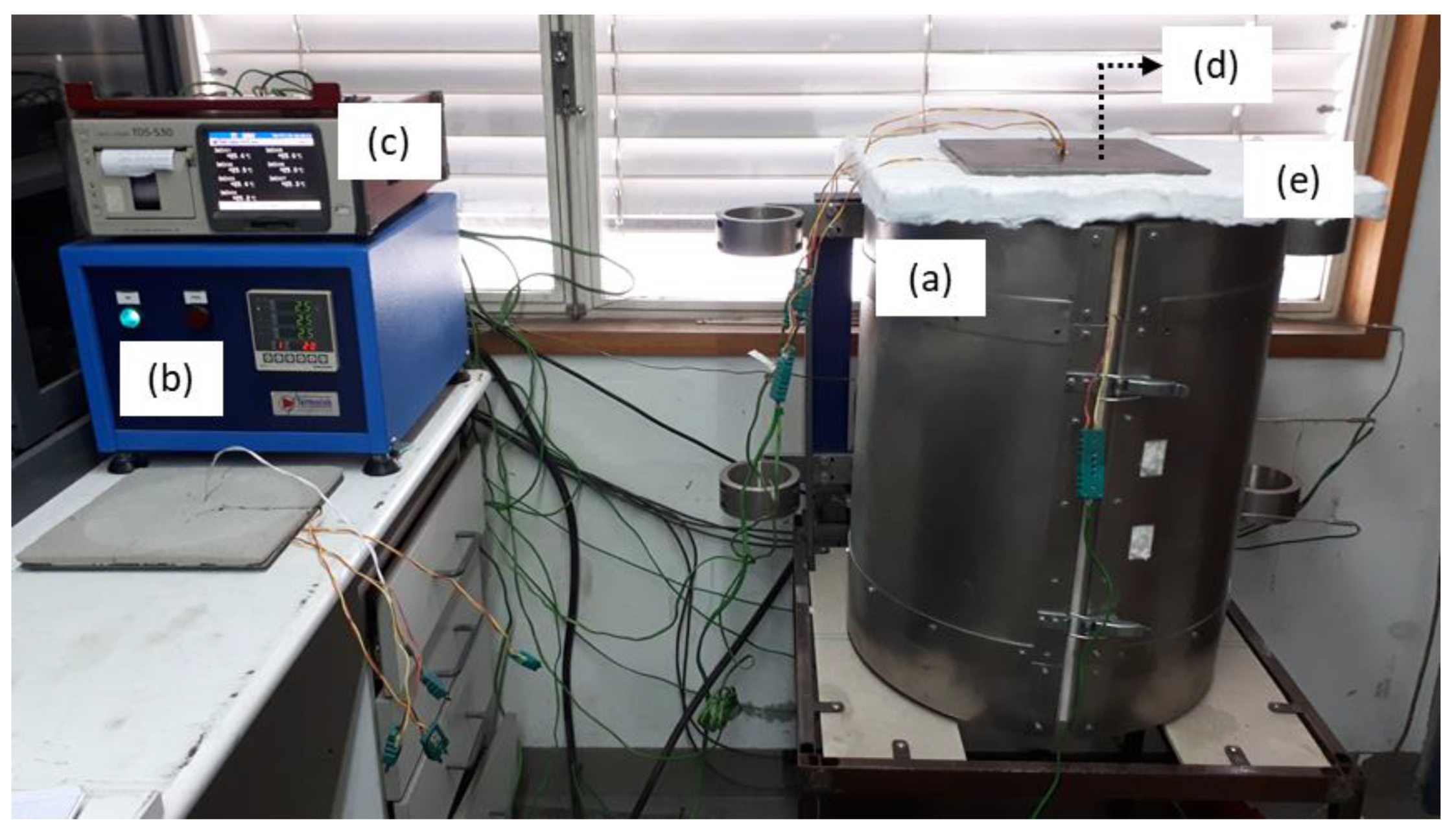
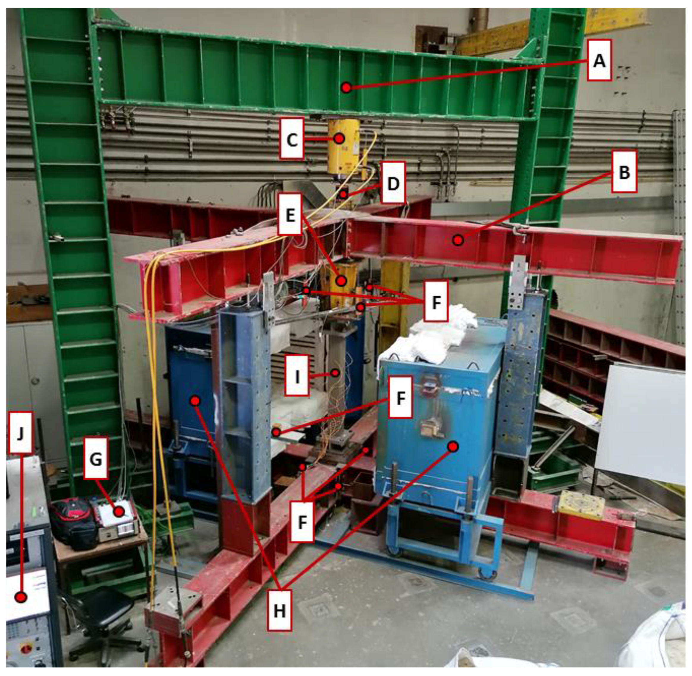
2.4. Experimental Testing System and Procedure

The experimental testing system (Figure 7) used in thermal analysis of steel plates consisted of a cylindrical oven with internal dimensions 400 mm in height and 250 mm in diameter, capable of reaching a maximum temperature of 1200 °C (a) and the respective oven controller (b). A Datalogger TDS-530 was used as a data acquisition system (c) to record the temperature readings. Regarding the test procedure, after sealing all the existing unions and holes of the oven with rock wool, a 8 cm thick rock wool blanket with a circular opening of 210 mm in diameter was also placed on the top of the oven (e), which allows the passage of heat from the interior of the oven to the specimen. Subsequently, the specimen (d) was placed on the top of the oven, i.e., on the rock wool blanket and centred with the barycentric axis of the oven.
In all tests, the specimens were placed in a suitable position to ensure perfect accommodation with the rock wool and thus avoid heat losses between the specimen and the oven. The specimen was heated at a heating rate of 15 °C/minute until reaching the desired temperature level (900 °C). Temperatures inside the specimen and the oven were measured every 5 s. When the target temperature in the specimen was reached, it was maintained uniform during 3 h and after, the test was given as concluded.
The experimental layout for the short steel columns (SSC) under fire conditions (Figure 8) consisted essentially of a reaction steel frame (A) to apply the serviceability load on the specimen, a support steel frame (B), a hydraulic jack (C), and an electric furnace (H).
This steel frame was defined by HEB 500 columns and a HEB 600 beam (A), with a stiffness capable of minimizing possible displacements of this steel structure during the tests. Additionally, a support 3D steel frame consisting of two frames (B) with HEB 300 columns and HEB 400 beams accommodate the testing specimen to similar actual boundary conditions. Regarding the test equipment, a 3 MN hydraulic jack (C) and its controller (J), a 3 MN load cell (D), and a 1 MN load cell (E) were used for measuring the compression forces. Ten linear variable displacement transducers were used for displacements measurements (F), a Datalogger (G) for data acquisition, and an electric furnace (H) to heat up the steel columns (I).
A hydraulic jack controlled by a servo-controlled central was used, and a preload of 50% of the design value of the loadbearing capacity of the columns at ambient temperature (ULS) was applied (727.8 kN) to simulate a service load on the specimen. After stabilising this loading in the specimen, the furnace was switched on and the specimen heated according to the temperature evolution established by the ISO 834 standard fire curve [41].
Due to the increase in temperature during the test, significant thermal elongation was generated in the specimen. The test was stopped based on the axial contraction criterion defined by ISO 834-1:1999 [42], which defines a limit shortening of the specimen according to its initial length, i.e., when the specimen could no longer support the initial applied load subjected to high temperatures. Thus, the final value of vertical deformation considered was 12.5 mm. Finally, the degree of detachment of the protective mortar and the failure mode in each specimen were observed.

3. Results and Discussion

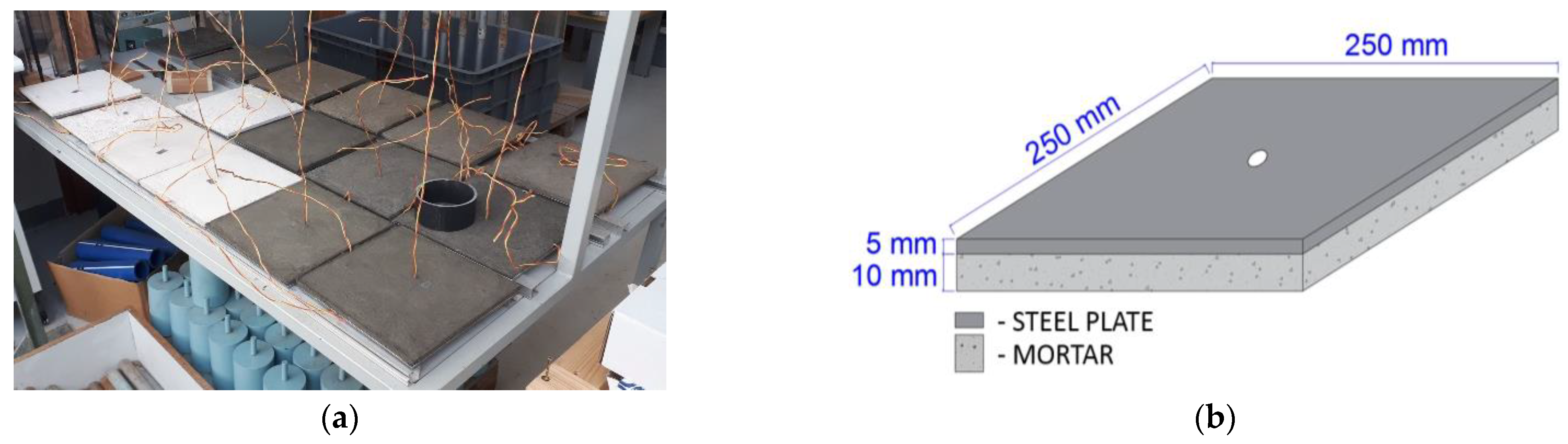
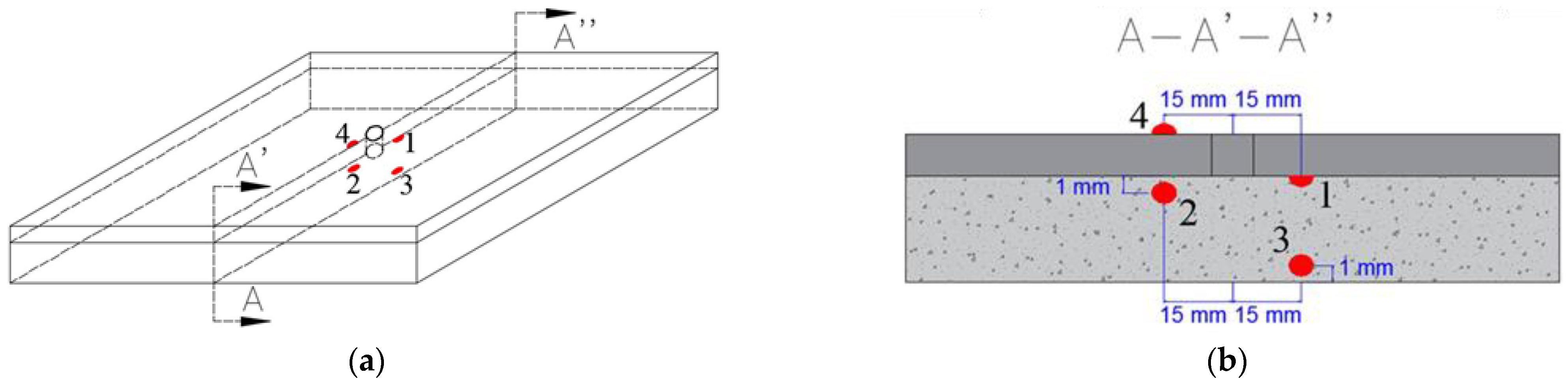
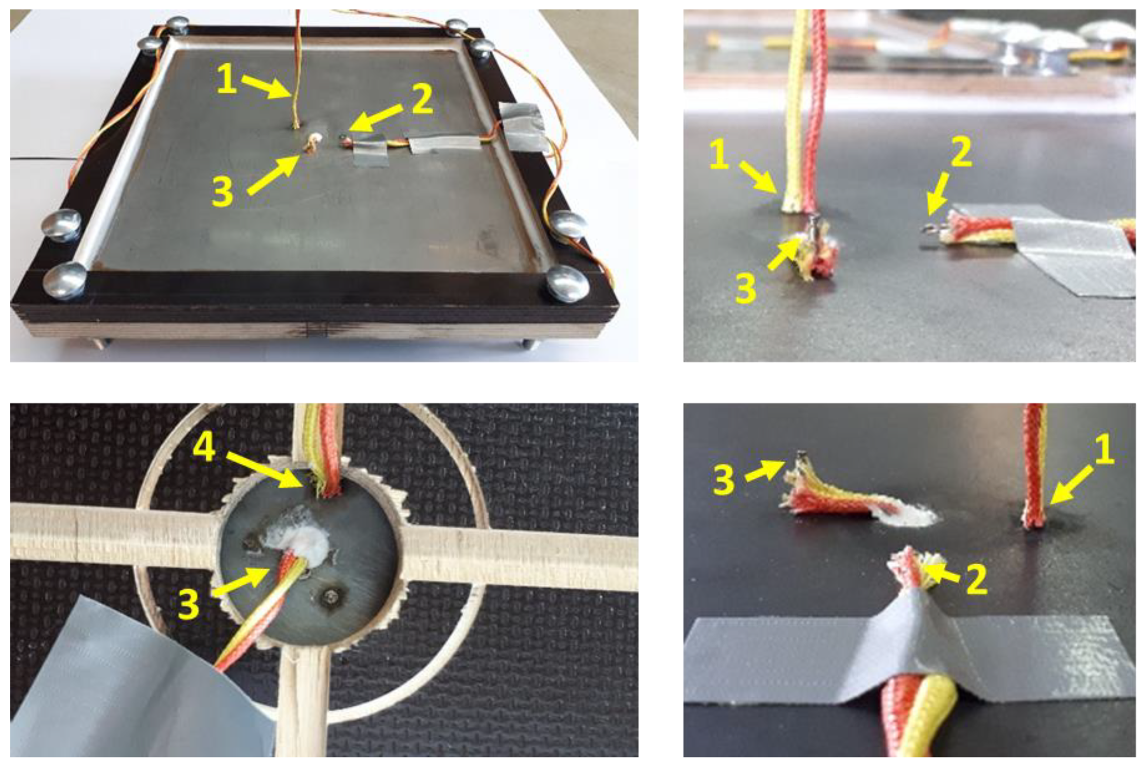
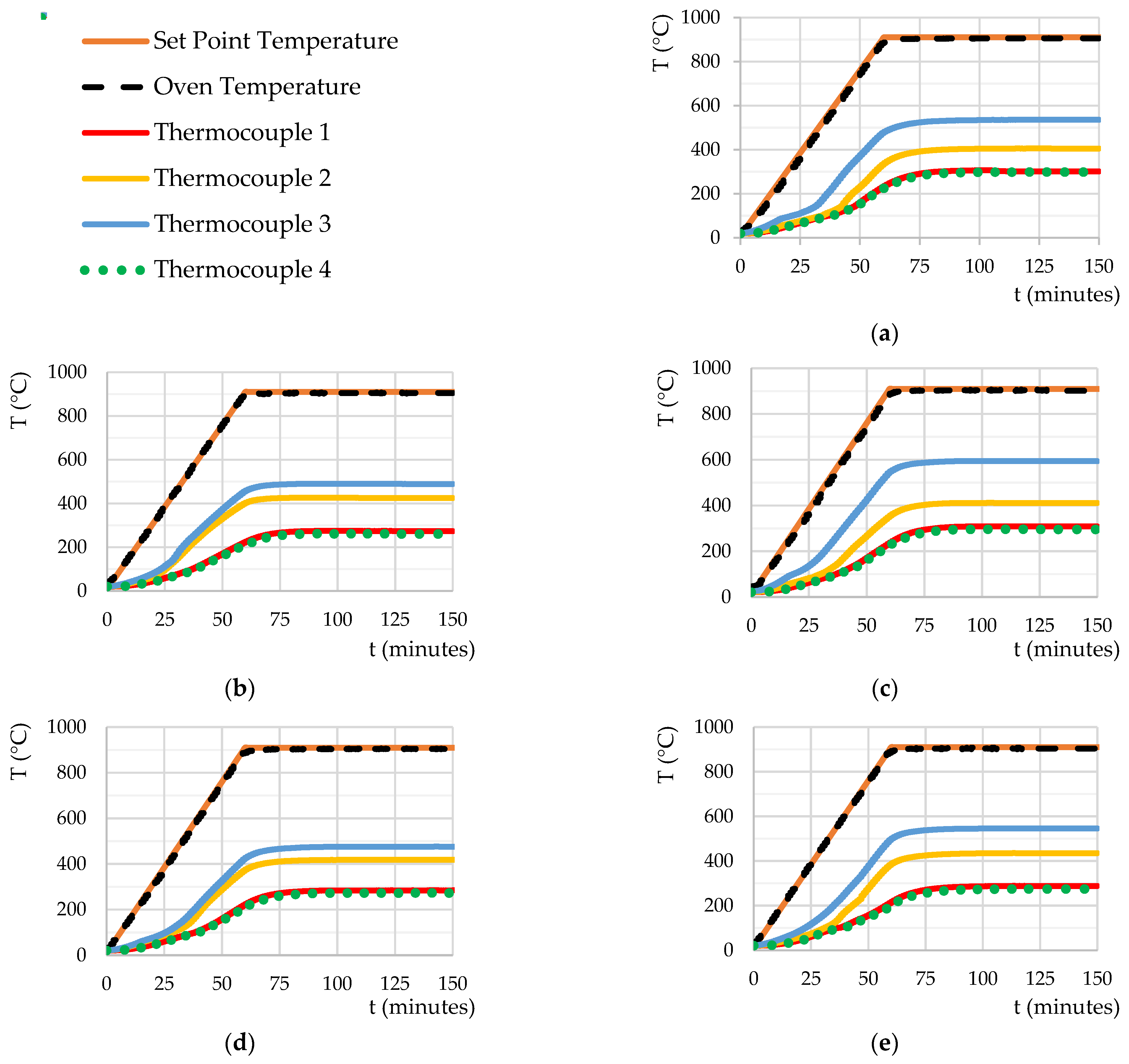
3.1. Steel Plate Specimens

The typical temperature evolution in the tested SP (CM, DCM, DGMP, DGMV, and DRCM) subjected up to 900 °C as a function of time, is shown in Figure 9.
It is possible to verify that the oven used in this experimental layout generated a heating curve (oven temperature curve) close to the desired heating curve (setpoint temperature). Thus, all specimens were exposed to a uniform and identical thermal action, making the tests comparable to each other.
Between 0 and 35 min, there was a slow and gradual increase in temperature of the specimens (CM, DCM, DGMP, DGMV, and DRCM) up to 100 °C. This temperature evolution was influenced by the water content in the mortars, i.e., by the energy required to heat and evaporate the liquid/crystallized water existing in the mortar. After this process, there was a sharp increase in temperature between 35 and 75 min, depending on the thermal conductivity of the mortar and the heating rate. Finally, until the end of the test, there was a slight increase in temperature in the specimen before a steady state temperature distribution was reached. This type of thermal development in the specimens was common for all compositions tests.
Based on the values obtained from the various tests carried out, it was possible to measure the average temperature on the inner surface of the steel plate of the specimen and thus establishing a direct relationship between the developed composition and its thermal protection capacity. The average values of the maximum temperature on the inner surface of the specimen’s steel plate (thermocouple 1) are shown in Table 5.
From the results presented in Table 5, it is possible to evaluate the thermal efficiency of the developed mortars: DCM, DGMP, DGMV, and DRCM, when compared with the best commercial solution tested (CM). Furthermore, it allows evaluating the influence of the size of the aggregates and the addition of silica micro- and nanoparticles on their thermal performance. The second column of Table 4 refers to mortars developed without NS and MS, in which the raw materials were obtained using the Los Angeles method (LA method). The temperature of CM was used as a reference for comparison (311 °C). The average temperature on the inner surface of the steel plate (ISSP) in the DCM, DGMP, DGMV, and DRCM mortars were 293, 310, 278, and 323 °C, respectively. These results show that the thermal protection provided by DCM, DGMP, and DGMV mortars were 5.8%, 0.3%, and 10.6% thermally more efficient than CM, respectively. However, the DRCM is thermally worse (3.9%) when compared to the CM. Finally, the compositions with vermiculite (DCM and DGMV) have better thermal efficiency.
The fourth column of Table 5 refers to mortars developed without NS and MS, in which the raw materials used were obtained using the industrial mill method (IM method). The average temperature in the ISSP in the DCM, DGMP, DGMV, and DRCM mortars were 309, 325, 275, and 366 °C, respectively. When comparing the ISSP temperatures of the DCM, DGMP, and DRCM mortals made with raw material from Los Angeles milling with the ISSP temperatures of the same mortars made with raw material from industrial milling, there was respectively a loss of insulation capacity by 5.5%, 4.6%, and 13.3% on average. As for the thermal performance of the DGMV, there is a slight improvement in thermal capacity of 1.1%. Overall, these results demonstrate that the reduction in grain size of the raw materials used (perlite and vermiculite) did not benefit the thermal performance of the tested compositions. Note that the reduction in the porosity of mortars may have an adverse effect in the fire insulation, but only neglecting the thermomechanical effect of mortars and the thermal deformation of the structural members, as it was the case in the thermal tests of the protected steel plates. Finally, compared to the commercial mortar with the developed mortals, DCM (cementitious mortar) and DGMV (gypsum mortar with vermiculite) had greater thermal insulation capacity, while mortars DGMP (gypsum mortar with vermiculite) and DRCM (refractory cementitious mortar) had lower thermal insulation capacity.
The sixth column of Table 5 refers to mortars developed with NS and MS, and the raw materials used were obtained by the LA method. This column only presents the results of the tests carried out with DCM, DGMP, and DGMV since the results of DRCM never presented a thermal insulation capacity higher than the commercial solution. The average temperature on the ISSP in the DCM, DGMP, and DGMV were 308, 275, and 268 °C, respectively. It appears that the introduction of NS and MS in the tested dosages slightly improved the thermal performance of the mortars by 11.3% for DGMP and 3.6% for DGMV. Comparing to CM (commercial mortal), both developed mortars with NS and MS (A2, A3, and A4) had greater thermal insulation capacity than the mortars without such particles.
Values for mortars with NS and MS and raw materials obtained by the IM method are presented in the eighth column. The average temperature in the ISSP in the DCM, DGMP, and DGMV were 297, 274, and 266 °C, respectively. The results demonstrate that the thermal protection provided by DCM, DGMP, and DGMV were 4.5%, 11.9%, and 14.5% thermally more efficient than CM, respectively. Comparing these results with those of the fourth column, the addition of NS and MS in DCM, DGMP, and DGMV improved their thermal performance by 3.9%, 15.7%, and 3.3%, respectively.
In addition, comparing these results with those of the sixth column, the manufacture of DCM, DGMP, and DGMV with raw materials processed with the IM method gives only a slight benefit on the thermal performance of these compositions, by 3.6%, 0.4%, and 0.8%, since nanoparticles tend to increase the shrinkage of materials. This is due to stronger retention of water, and capillary forces developed.
Briefly, the differences in the results presented may be due to the higher porosity of the materials obtained through the LA method than the IM method, i.e., in general the higher the porosity, the higher the thermal insulation is. However when micro- and nanoparticles of silica were added, the thermal responce of fire protection materials might be different (as it was the case) since those particles can work as fire barriers, i.e., close more efficiently some porous in the materials.
The average crack width values of the mortars after carrying out the tests at high temperatures are presented in Table 6, and specimens after testing and the respective type of cracking are illustrated in Table 7. Based on the crack withs presented in the column of the Table 6, the CM has the highest average crack width compared to the DCM, DGMP, DGMV, and DRCM. Compared with CM, mortars DCM, DGMP, DGMV, and DRCM have lower average crack widths by 55.5%, 80.5%, 63.4% and 76.6%.
It was shown that the average crack width of the specimens manufactured with raw materials from the IM method were higher than those of the specimens manufactured with raw materials from the LA method, except for the DGMP where the crack width was the same.
In general terms, the addition of NS and MS tends to increase the cracking of the developed compositions, except for the DGMV, as shown in Table 7. Furthermore, it could be observed that the crack width was worse than the number of cracks (with smaller widths). To sum up, crack widths higher than 0.6 mm might compromise their thermal protection.

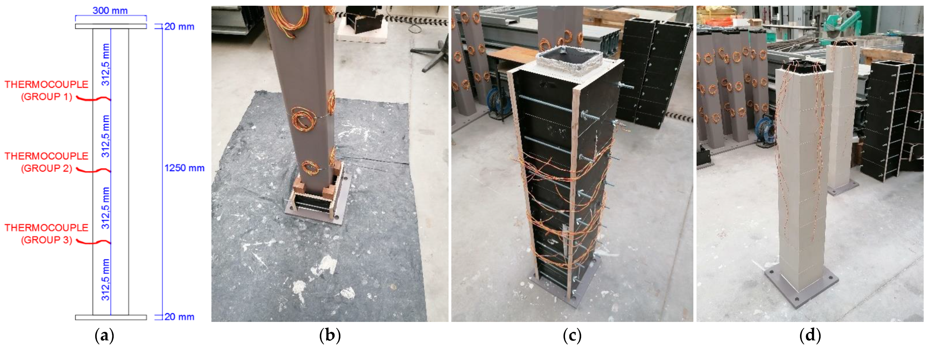
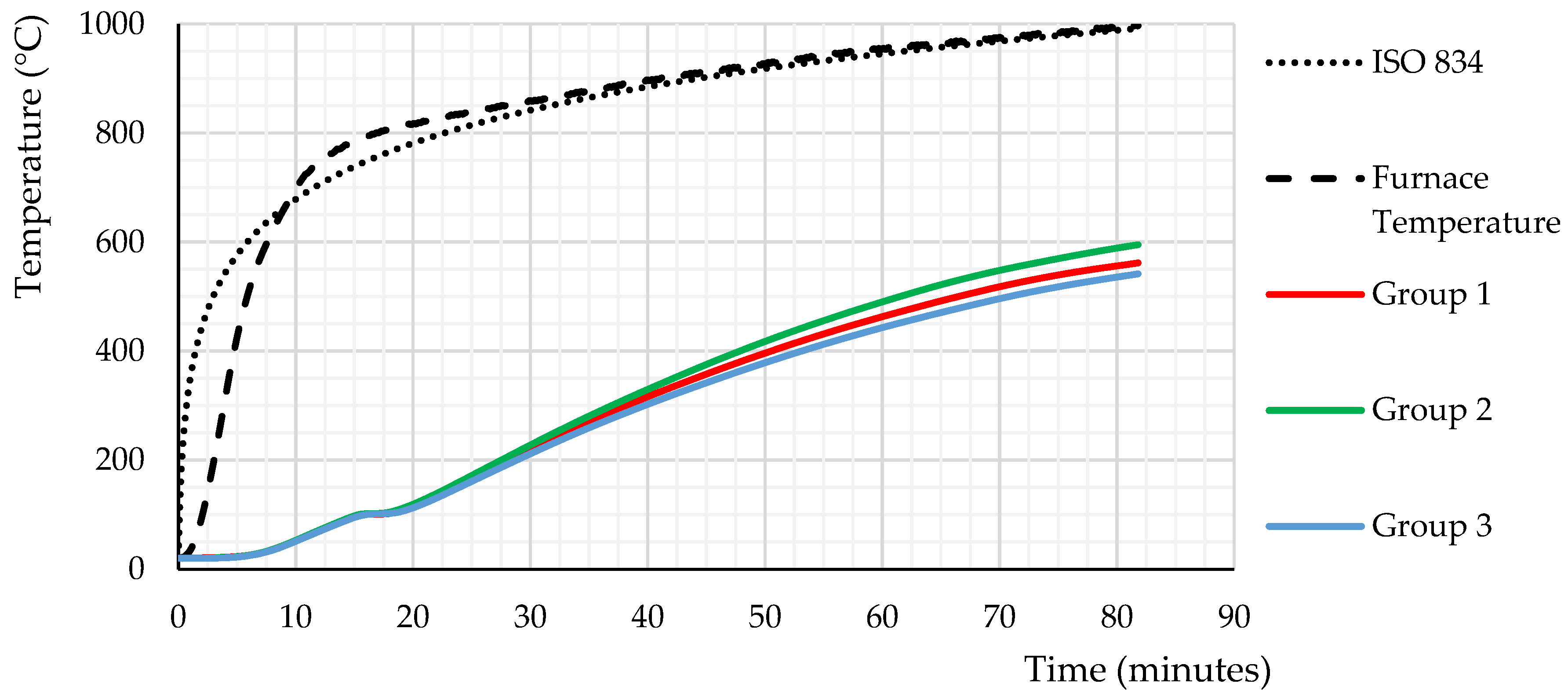
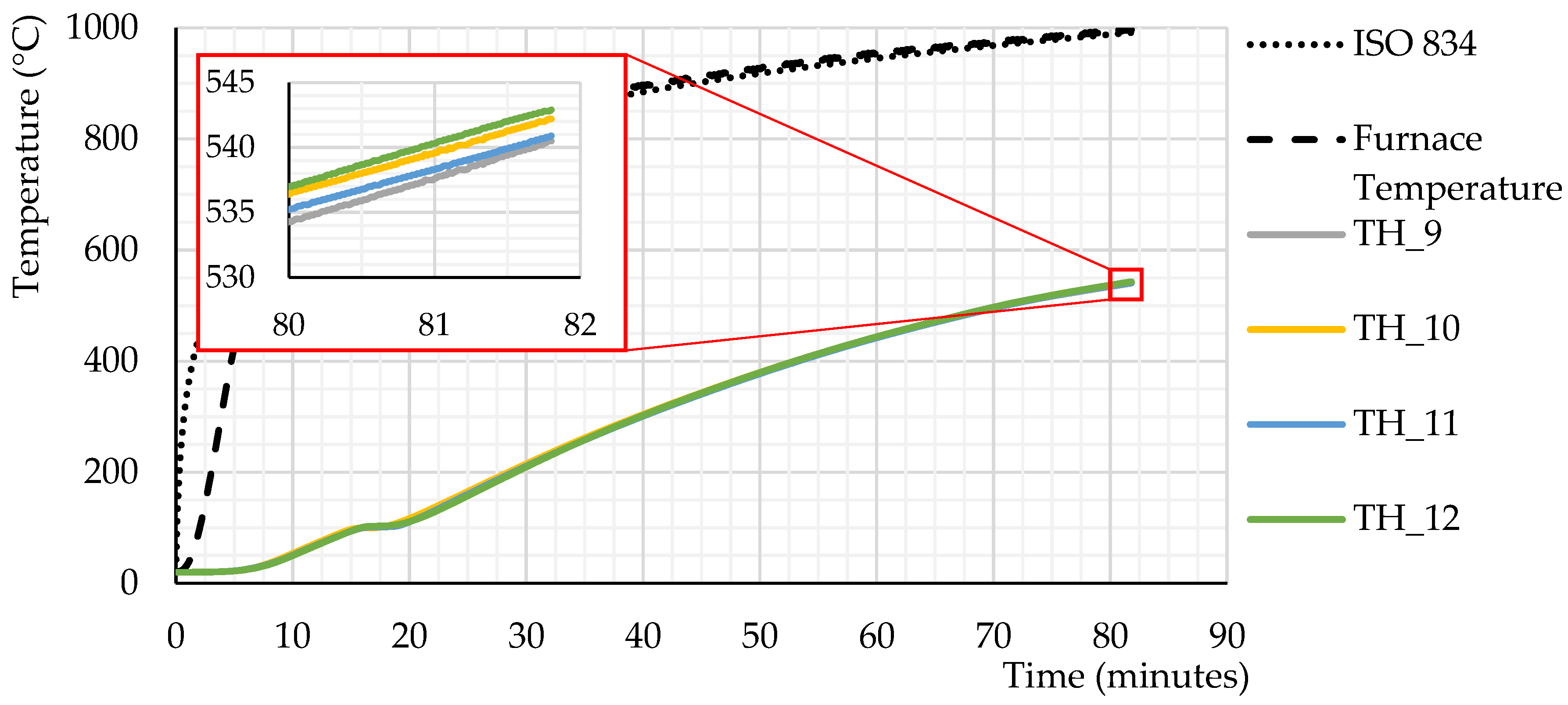
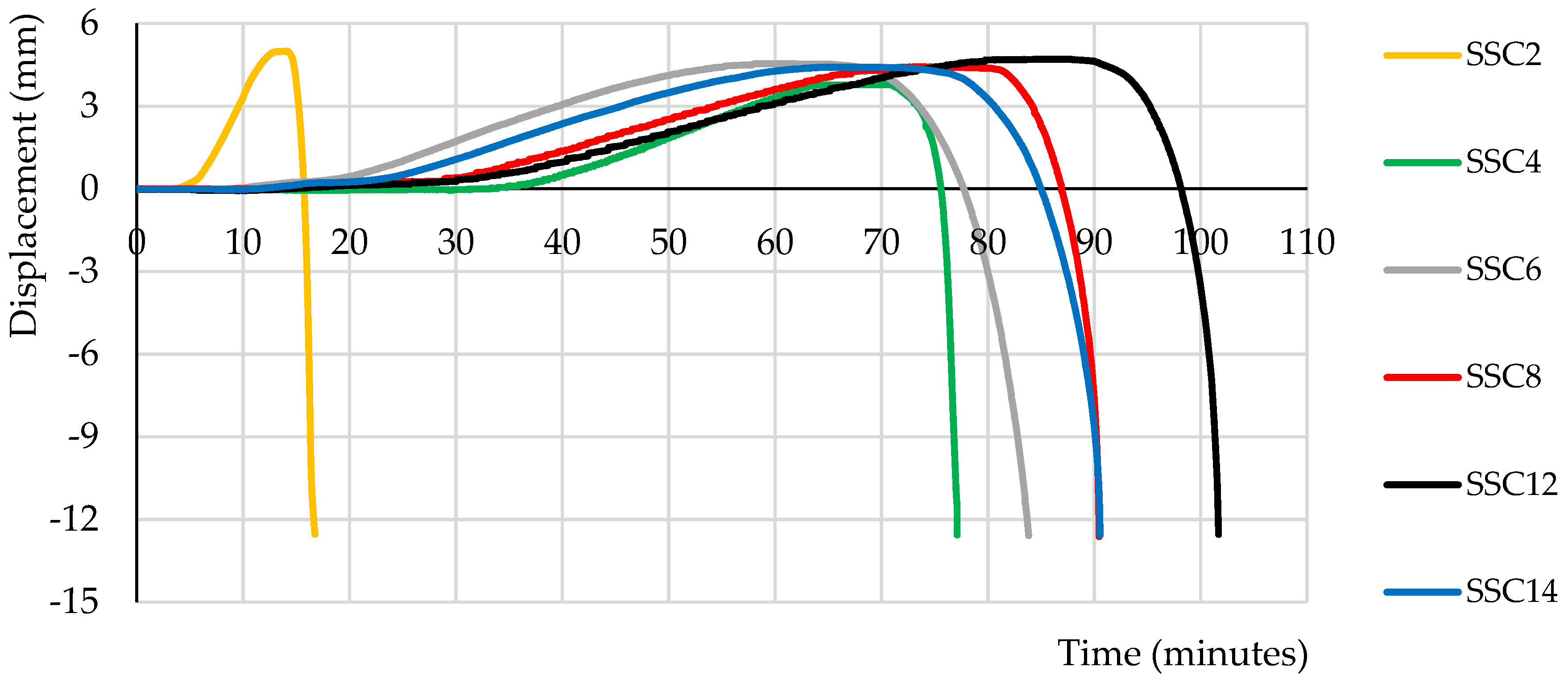
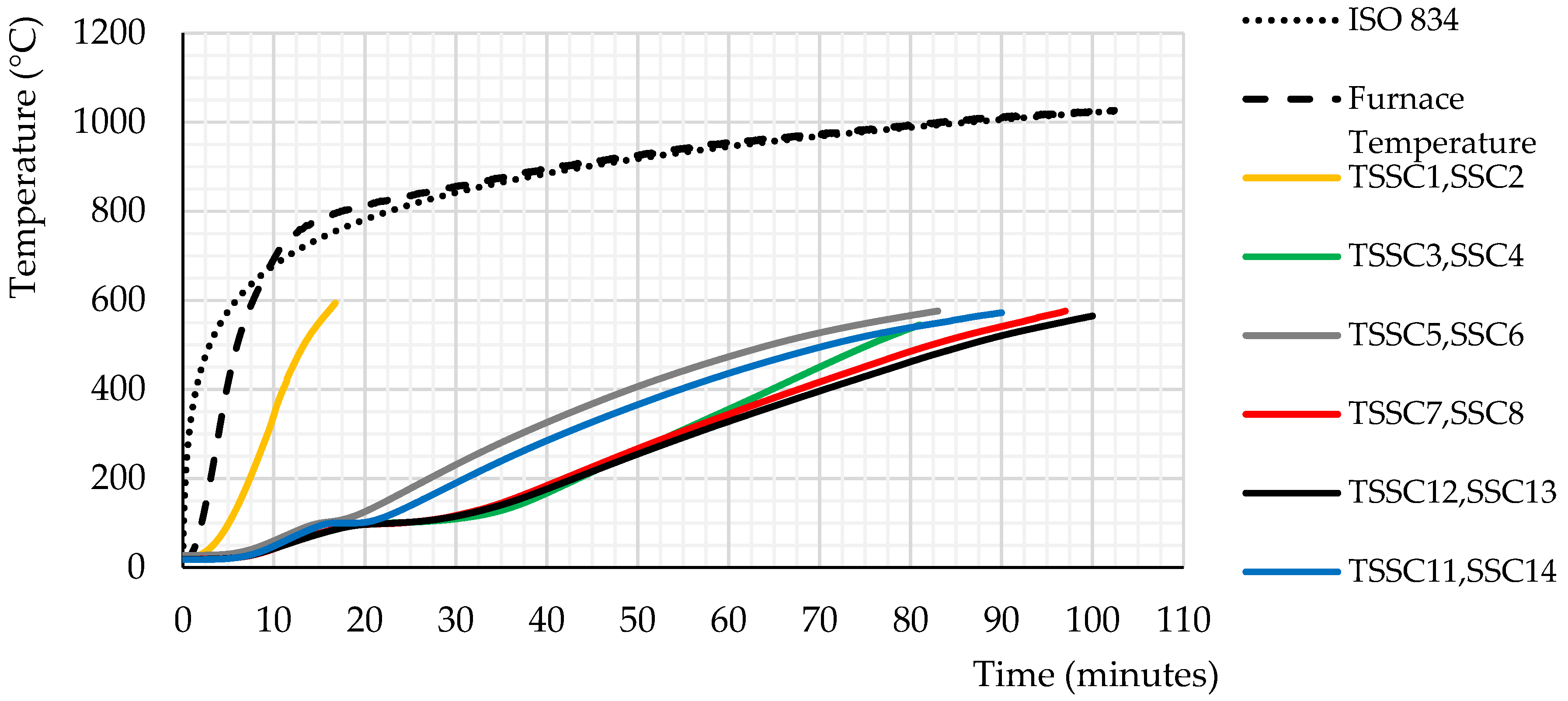
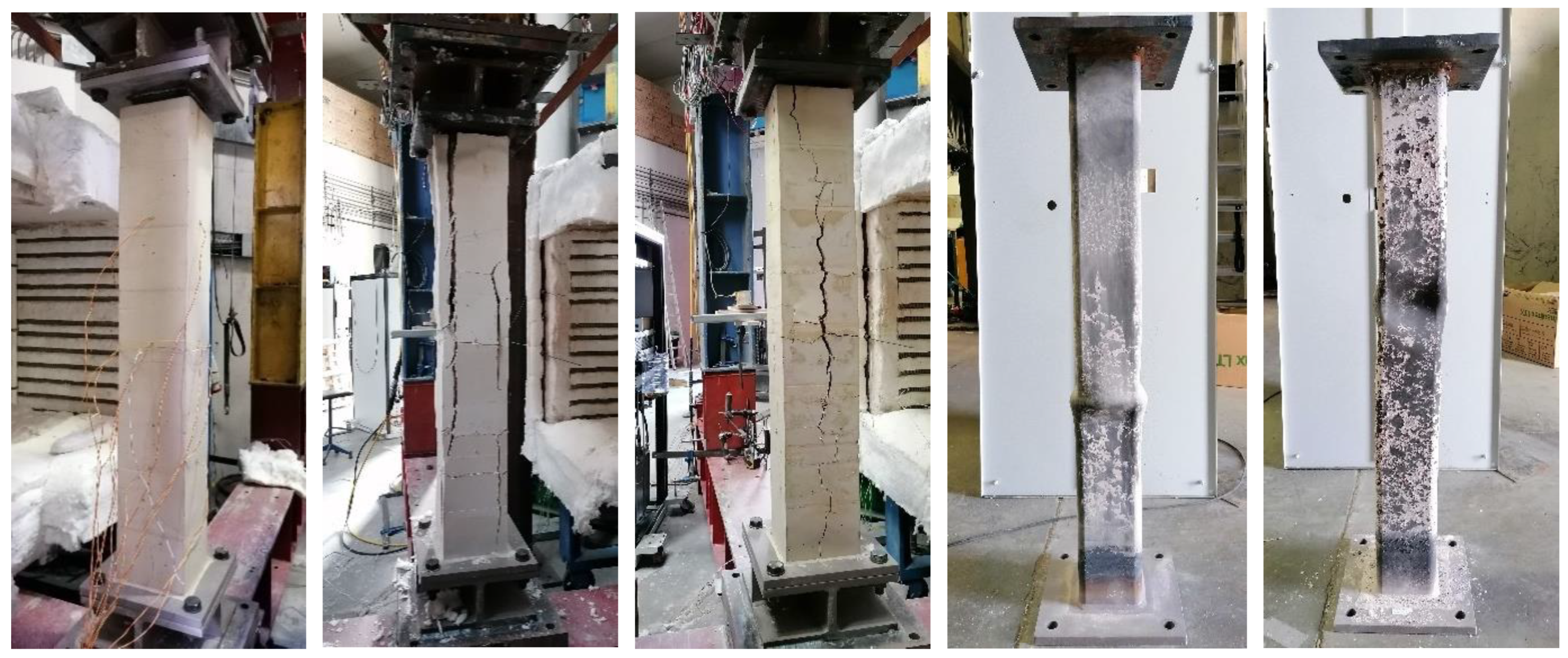
3.2. Short Steel Columns Specimens

Regarding the protected square-section short steel columns (SSC), the assessment of the column temperature was based on the arithmetic average of the temperatures obtained from the 12 thermocouples welded to the steel column, which were distributed into three sections with four thermocouples each one (Figure 6 and Figure 10). As an example, Figure 11 shows the temperature evolution in steel at the lower section of the column where temperatures were recorded (Figure 6).
Based on Figure 10, it is possible to observe that the furnace temperatures slightly delayed the initial minutes concerning the ISO 834 standard fire curve. This part of the curve is difficult to reproduce in an electric furnace, and this becomes worse for larger furnaces (high initial thermal inertia). However, near 9 min after the beginning of the heating, the furnace temperatures followed close to the ISO 834 standard fire curve (ISO 834-1, 1999). Nevertheless, the evolution of temperatures inside the furnace over time was uniform in all fire tests, meaning that the tests were comparable.
Based on Figure 11, it is possible to observe that the temperature development recorded in the four thermocouples of group 3 was similar. There is only a difference of 3.3 °C between the thermocouple with the highest (TH_12) and the lowest temperature (TH_9) at column failure.
Until the specimens became unstable, graphs were generated with the evolution of the vertical deformation of the specimen as a function of time (Figure 12) to identify the critical experimental temperature, as well as graphs of temperature evolution as a function of time (Figure 13).
Table 8 shows the average temperature values acquired in the specimens after 15, 30, 60, and 90 min and the average temperature values for the failure instants of each specimen. The critical design temperature calculated according to EN 1993-1-2:2005 [41] for this short steel column was 586.7 °C.
In Figure 12, the tested SSC2 failed at 17 min, SSC4 at 77 min, SSC6 at 84 min, SSC8 at 95 min, SSC12 at 102 min, and SSC14 at 91 min, corresponding to the temperature of 617, 531, 585, 572, 566, and 559 °C, respectively (see also Table 8). In Figure 13 and Table 8, it can be seen that the commercial mortar has a more effective thermal protection for lower temperatures (the highest delay in the temperature rise at the beginning of the test). However, for temperatures higher than 400 °C, its thermal capacity tends to decrease due to the degradation of the mortar (the highest temperature rise rate at the ending of the test).
Figure 14 depicts the specimen before and after being tested. Regarding the instability modes of the steel columns, local instability was observed despite the column being a class 1 cross-section under fire conditions.
The results from Table 8 clearly show that the application of mortars works as a good thermal barrier to fire, since columns without passive fire protection failed after 17 min of testing, whereas the protected columns failed on average, beyond 81 min. Furthermore, the results also show that the thermal protection of mortars developed in the laboratory was more efficient than that provided by the commercial mortars. Finally, it appears that the introduction of the NS and MS slightly improved the thermal performance of the mortars developed in the laboratory.
Table 8 shows that the specimen without passive fire protection presented a fire resistance rating (FRR) of 15 min (R15), and the protected specimens with the CM allowed a FRR of R60. Concerning the thermal performance of the mortars developed in the laboratory, it was found that the specimens protected with the DCM had a FRR of R60. When NS and MS were added to its composition, a FRR increased to R90. The specimens protected with the DGMP, with and without NS and MS, presented a FRR of R90.
The findings results obtained from the short steel columns protected with the different mortars types were in agreement with the ones obtained in the tests carried out on the protected steel plates, which makes these exploratory tests useful for preliminary selection of promising fire protection materials.

4. Conclusions

The objective of this work was to develop gypsum or cement-based mortars for passive fire protection and to evaluate the influence of aggregate size and the addition of silica micro- and nanoparticles on its thermal performance. The thermal performance of these mortars in short steel columns under a compression service load and subjected to high temperatures was assessed. The following conclusions can be drawn:
  • The furnace, the dimensions of the specimens, and the test procedure adopted in the tests at high temperatures allowed an adequate thermal exposure of the specimens. It allowed the evaluation of the thermal performance of the various mortars tested.
  • Some mortars developed in the laboratory (DCM, DGMP, and DGMV) have better thermal performance when compared with the best commercial solution tested (CM). Furthermore, in this set of mortars without nano- and microparticles of silica, the mortars with vermiculite in their constitution were those with the best thermal performance.
  • Most mortars with raw material milled through the Los Angeles method had better thermal performance than mortars developed with raw material processed through the Industrial Mill method. However, if nano- and microparticles of silica are added in their composition, the mortars developed with raw material obtained through the Industrial Mill method may have a slightly superior thermal performance.
  • The addition of nano- and microparticles of silica improves the insulating capacity of the mortars.
  • Overall, the results demonstrate that the reduction in grain size of the raw materials used (perlite and vermiculite) did not benefit the thermal performance of the tested compositions.
  • Regarding the cracking of the mortars, it was concluded that perlite (DGMP) contributes to its low value. It was also concluded that, in general terms, the addition of NS and MS tends to increase the cracking degree of the developed compositions.
  • The compositions that use gypsum as a binder (DGMP and DGMV) had the best thermal insulation capacity. Under the tested conditions, it was found that 10 mm of mortar coating was sufficient to form an efficient thermal barrier, reducing the ISSP temperature by approximately 70% of the temperature recorded inside the oven (900 °C).
  • The thermal protection level of columns with the mortar developed in the laboratory with the best overall thermal performance (DGMP with nano- and microparticles of silica) was 19% more efficient than the commercial solution and increases by 5.9 times the fire resistance of an unprotected short steel column. These results demonstrated the actual impact that the application of such mortars can have as passive fire protection of steels structures.
Bearing in mind the experimental findings obtained in this research study, further experimental tests on short steel columns with the developed mortars and new ones by using different additives as well as with different loading conditions will be carried out in the near future.

Author Contributions

Conceptualization, H.C. and A.S. (Aldina Santiago); methodology, H.C.; software, A.S. (Aldina Santiago); validation, L.L., L.D. and A.S. (Ashkan Shahbazian); formal analysis, H.C.; investigation, H.C.; resources, A.S. (Aldina Santiago); data curation, A.S. (Aldina Santiago); writing—original draft preparation, H.C.; writing—review and editing, L.L.; visualization, H.C.; supervision, H.C.; project administration, A.S. (Aldina Santiago); funding acquisition, A.S. (Aldina Santiago). All authors have read and agreed to the published version of the manuscript.

Funding

This research was funded by the Portuguese Foundation for Science and Technology (FCT), grant number PTDC/ECI-EGC/31850/2017.

Institutional Review Board Statement

Not applicable.

Informed Consent Statement

Not applicable.

Acknowledgments

The authors gratefully acknowledge the Portuguese Foundation for Science and Technology (FCT) for its support under the framework of research project PTDC/ECI-EGC/31850/2017 (NANOFIRE—Thermal and Mechanical behaviour of Nano Cements and their application in steel construction as fire protection) and also to the University of Coimbra (UC) for their support under the Scientific Employment Stimulus Programme given to the first author, as well as to the European Regional Development Fund, the European Social Fund, and European Structural and Investment Funds. This work was also financed by FEDER funds through the Competitivity Factors Operational Programme—COMPETE and by national funds through FCT within the scope of the project POCI-01-0145-FEDER-007633 and through the Regional Operational Programme CENTRO2020 within the scope of the project CENTRO-01-0145-FEDER-000006.

Conflicts of Interest

The authors declare no conflict of interest.

Abbreviations

CMCommercial passive protection solution used as a reference mortar
CPPSCommercial passive protection solution
DCMDeveloped cementitious mortar
DGMPDeveloped gypsum mortar with perlite
DGMVDeveloped gypsum mortar with vermiculite
DRCMDeveloped refractory cementitious mortar
ECExpanded clay
EPExpanded perlite
ERCEletroland refractory cement
ESMHTExposed surface of the mortar to high temperatures
ESSPExternal surface of the steel plate of the test specimen
EVExpanded vermiculite
GPGypsum powder
IGNCommercial passive protection solution 1
IMIndustrial mill method
IRCIsidac 40 refractory cement
ISSPInner surface of the steel plate of the test specimen
LALos Angeles method
MSMicroparticles of silica
NSNanoparticles of silica
PCPortland cement CEM II/B-L 32.5
PPPolypropylene fibers
PP/BPolypropylene fibers cement ratio in weight %
RCRefractory cement
RHRelative humidity
SDStandard deviation
SPSteel plate
SSSilica sand
SSCShort steel columns
TTemperature
tTime
THThermocouple
TRCTopeca M40 refractory cement
USMHTUnexposed surface of the mortar to high temperatures
VERCommercial passive protection solution 2
WWater
W/BWater binder (cement or gypsum) ratio in weight %

References

  1. Gervásio, H.; da Silva, L.S.O.E. Comparative life-cycle analysis of steel-concrete composite bridges. Struct. Infrastruct. Eng. 2008, 4, 251–269. [Google Scholar] [CrossRef]
  2. European Commission. Communication from the European Commission: The Competitiveness of the Construction Industry, in COM; European Commission: Brussels, Belgium, 1997; Volume 97, p. 539. [Google Scholar]
  3. Gervásio, H.; da Silva, L.S. A sustentabilidade do aço. In Construção Metáica e Mista V; CMM: Lisboa, Portugal, 2005; pp. 719–730. [Google Scholar]
  4. Devine, J. Improving Ductility of Sprayed Fire Resistant Materials; Worcester Polytechnic Institute: Worcester, MA, USA, 2018. [Google Scholar]
  5. Islam, M.; Ali, R.B. Fire Protection of Steel Structure: An Overall Review. World Sci. News 2018, 102, 131–145. [Google Scholar]
  6. Outinen, J.; Mäkeläinen, P. Mechanical properties of structural steel at elevated temperatures and after cooling down. Fire Mater. 2004, 28, 237–251. [Google Scholar] [CrossRef]
  7. Puri, R.G.; Khanna, A.S. Intumescent coatings: A review on recent progress. J. Coatings Technol. Res. 2017, 14, 1–20. [Google Scholar] [CrossRef]
  8. Santiago, A.; Silva, L.S.; Vaz, G.; Real, P.V.; Lopes, A.G. Experimental investigation of the behaviour of a steel sub-frame under a natural fire. Steel Compos. Struct. 2008, 8, 243–264. [Google Scholar] [CrossRef]
  9. Wald, F.; Chlouba, J.; Uhlíř, A.; Kallerová, P.; Štujberová, M. Temperatures during fire tests on structure and its prediction according to Eurocodes. Fire Saf. J. 2009, 44, 135–146. [Google Scholar] [CrossRef]
  10. Franssen, J.M.; Cooke, G.M.E.; Latham, D.J. Numerical simulation of a full scale fire test on a loaded steel framework. J. Constr. Steel Res. 1995, 35, 377–408. [Google Scholar] [CrossRef]
  11. Lamont, S.; Usmani, A.S.; Gillie, M. Behaviour of a small composite steel frame structure in a “long-cool” and a “short-hot” fire. Fire Saf. J. 2004, 39, 327–357. [Google Scholar] [CrossRef]
  12. Usmani, A.S.; Rotter, J.M.; Lamont, S.; Sanad, A.M.; Gillie, M. Fundamental principles of structural behaviour under thermal effects. Fire Saf. J. 2001, 36, 721–774. [Google Scholar] [CrossRef]
  13. Wang, Y.C.; Lennon, T.; Moore, D.B. The behaviour of steel frames subject to fire. J. Constr. Steel Res. 1995, 35, 291–322. [Google Scholar] [CrossRef]
  14. Wang, Y.C.; Dai, X.H.; Bailey, C.G. An experimental study of relative structural fire behaviour and robustness of different types of steel joint in restrained steel frames. J. Constr. Steel Res. 2011, 67, 1149–1163. [Google Scholar] [CrossRef]
  15. Vaz-Ramos, J.; Santiago, A.; Portugal, A.; Durães, L. Synthesis of silica nanoparticles to enhance the fire resistance of cement mortars. Fire Res. 2019, 3, 44–48. [Google Scholar] [CrossRef]
  16. Chen, Y.Y.; Chuang, Y.J.; Huang, C.H.; Lin, C.Y.; Chien, S.W. The adoption of fire safety management for upgrading the fire safety level of existing hotel buildings. Build. Environ. 2012, 51, 311–319. [Google Scholar] [CrossRef]
  17. Liu, H.; Wang, C.; Cordeiro, I.M.C.; Yuen, A.C.Y.; Chen, Q.; Chan, Q.N.; Kook, S.; Yeoh, G.H. Critical assessment on operating water droplet sizes for fire sprinkler and water mist systems. J. Build. Eng. 2020, 28, 100999. [Google Scholar] [CrossRef]
  18. Chow, W.K. Aspects of fire safety in ultra highrise buildings. Int. J. Eng. Perform.-Based Fire Codes 2004, 6, 47–52. [Google Scholar]
  19. Kodur, V.; Kumar, P.; Rafi, M.M. Fire hazard in buildings: Review, assessment and strategies for improving fire safety. PSU Res. Rev. 2019, 4, 1–23. [Google Scholar] [CrossRef]
  20. Sakkas, K.; Nomikos, P.; Sofianos, A.; Panias, D. Inorganic polymeric materials for passive fire protection of underground constructions. Fire Mater. 2013, 37, 140–150. [Google Scholar] [CrossRef]
  21. Kandare, E.; Griffin, G.J.; Feih, S.; Gibson, A.G.; Lattimer, B.Y.; Mouritz, A.P. Fire structural modelling of fibre-polymer laminates protected with an intumescent coating. Compos. Part A Appl. Sci. Manuf. 2012, 43, 793–802. [Google Scholar] [CrossRef]
  22. Lawson, R.M.; Newman, G.M. Fire Resistant Design of Steel Structures, a Handbook to BS 5950: Part 8; Steel Construction Institute: London, UK, 1990. [Google Scholar]
  23. Caetano, H.; Vaz-Ramos, J.; Santiago, A.; Duraes, L.; Portugal, A. Desenvolvimento de argamassas cimentícias com nanosílica como protecção passiva para elementos metálicos. In Proceedings of the XII Congresso de Construção Metálica e Mista, Coimbra, Portugal, 21–22 November 2019. [Google Scholar]
  24. Aggarwal, P.; Singh, R.P.; Aggarwal, Y. Use of nano-silica in cement based materials—A review. Cogent Eng. 2015, 2, 1–11. [Google Scholar] [CrossRef]
  25. Singh, L.P.; Karade, S.R.; Bhattacharyya, S.K.; Yousuf, M.M.; Ahalawat, S. Beneficial role of nanosilica in cement based materials—A review. Constr. Build. Mater. 2013, 47, 1069–1077. [Google Scholar] [CrossRef]
  26. Rashad, A.M. A comprehensive overview about the effect of nano-SiO2 on some properties of traditional cementitious materials and alkali-activated fly ash. Constr. Build. Mater. 2014, 52, 437–464. [Google Scholar] [CrossRef]
  27. Li, H.; Xiao, H.; Yuan, J.; Ou, J. Microstructure of cement mortar with nanoparticles. Compos. Part B Eng. 2004, 35, 185–189. [Google Scholar] [CrossRef]
  28. El-Gamal, S.M.A.; Abo-El-Enein, S.A.; El-Hosiny, F.I.; Amin, M.S.; Ramadan, M. Thermal resistance, microstructure and mechanical properties of type I Portland cement pastes containing low-cost nanoparticles. J. Therm. Anal. Calorim. 2018, 131, 949–968. [Google Scholar] [CrossRef]
  29. Jittabut, P.; Pinitsoontorn, S.; Thongbai, P.; Amornkitbamrung, V.; Chindaprasirt, P. Effect of nano-silica addition on the mechanical properties and thermal conductivity of cement composites. Chiang Mai J. Sci. 2016, 43, 1160–1170. [Google Scholar]
  30. Laím, L.; Caetano, H.; Santiago, A. Review: Effects of nanoparticles in cementitious construction materials at ambient and high temperatures. J. Build. Eng. 2021, 35, 102008. [Google Scholar] [CrossRef]
  31. Singh, M.; Garg, M. Perlite-based building materials—A review of current applications. Constr. Build. Mater. 1991, 5, 75–81. [Google Scholar] [CrossRef]
  32. Rashad, A.M. Vermiculite as a construction material—A short guide for Civil Engineer. Constr. Build. Mater. 2016, 125, 53–62. [Google Scholar] [CrossRef]
  33. Abidi, S.; Nait-Ali, B.; Joliff, Y.; Favotto, C. Impact of perlite, vermiculite and cement on the thermal conductivity of a plaster composite material: Experimental and numerical approaches. Compos. Part B Eng. 2015, 68, 392–400. [Google Scholar] [CrossRef]
  34. Abdel-Hafez, L.M.; Abouelezz, A.E.Y.; Hassan, A.M. Behavior of RC columns retrofitted with CFRP exposed to fire under axial load. HBRC J. 2015, 11, 68–81. [Google Scholar] [CrossRef] [Green Version]
  35. Manzello, S.L.; Gann, R.G.; Kukuck, S.R.; Lenhert, D.B. Influence of gypsum board type (X or C) on real fire performance of partition assemblies. Fire Mater. 2007, 31, 425–442. [Google Scholar] [CrossRef]
  36. Hodhod, O.A.; Rashad, A.M.; Abdel-Razek, M.M.; Ragab, A.M. Coating protection of loaded RC columns to resist elevated temperature. Fire Saf. J. 2009, 44, 241–249. [Google Scholar] [CrossRef]
  37. Correia, J.R.; Branco, F.A.; Ferreira, J.G. The effect of different passive fire protection systems on the fire reaction properties of GFRP pultruded profiles for civil construction. Compos. Part A. 2010, 41, 441–452. [Google Scholar] [CrossRef]
  38. Kamal, O.A.; Hamdy, G.A.; Abou-Atteya, M.A. Efficiency of coating layers used for thermal protection of FRP strengthened beams. HBRC J. 2014, 10, 183–190. [Google Scholar] [CrossRef] [Green Version]
  39. Khoury, G.A.; Majorana, C.E.; Pesavento, F.; Schrefler, B.A. Modelling of heated concrete. Mag. Concr. Res. 2002, 54, 77–101. [Google Scholar] [CrossRef]
  40. Rilem Technical Committee. 200-HTC: Mechanical concrete properties at high temperatures–modelling and applications—Part 1: Introduction—General presentation. Mater. Struct. 2007, 40, 841–853. [Google Scholar] [CrossRef] [Green Version]
  41. EN 1993-1-2:2005. Eurocódigo 3—Projecto de Estruturas de aço—Parte 1–2: Regras Gerais, Verificação da Resistência ao Fogo; Comité Europeu de Normalização: Bruxelas, Belgium, 2005. [Google Scholar]
  42. ISO 834-1:1999. Ensaios de Resistência ao Fogo—Elementos de Construção de Edifícios—Parte 1: Requisitos Gerais; International Organization for Standardization: Geneva, Switzerland, 1999; pp. 1–33. [Google Scholar]
Figure 1. Mould used in the manufacture of SP: (a) mould components; (b) mould assembly.
Applsci 12 02093 g001
Figure 2. Manufacture of specimens: (a) Hobart N50 mixer; (b) fresh mortar in the mixer container; (c) steel plate with thermocouples applied; (d) specimen in the process of curing during the first 48 h.
Applsci 12 02093 g002
Figure 3. (a) Specimens in the process of curing; (b) specimen schematic representation and respective dimensions.
Applsci 12 02093 g003
Figure 4. Schematic view of thermocouples. (a) A-A’-A” cross-section in the middle of the specimen; (b) arrangement and designation of thermocouples.
Applsci 12 02093 g004
Figure 5. Identification of thermocouples, 1–4, on the specimen following Figure 4.
Applsci 12 02093 g005
Figure 6. Distribution of thermocouples (a) and fabrication of specimens, preconcreting (b), concreting on the short steel columns (c), and concrete specimen without formwork (d).
Applsci 12 02093 g006
Figure 7. Experimental setup: (a) cylindrical oven (b) oven controller (c) data acquisition system (d) specimen (e) rock wool.
Applsci 12 02093 g007
Figure 8. Experimental system used in the laboratory to test SSCS. The letters in this figure are defined in the following text.
Applsci 12 02093 g008
Figure 9. Temperature evolution in the tested SP: (a) Specimen 26 of CM; (b) Specimen 30 of DCM; (c) Specimen 36 of DGMP; (d) Specimen 40 of DGMV; (e) Specimen 48 of DRCM.
Applsci 12 02093 g009
Figure 10. Evolution of the average temperature in the three groups of thermocouples in specimen 5 of SSC.
Applsci 12 02093 g010
Figure 11. Evolution of the temperature of the four thermocouples in group 3 of specimen 5 of SSC.
Applsci 12 02093 g011
Figure 12. Evolution of vertical deformation in the specimens of SSC as a function of time.
Applsci 12 02093 g012
Figure 13. Evolution of temperature in the specimens of SSC as a function of time.
Applsci 12 02093 g013
Figure 14. Photos of the specimens of SSC before and after tested, as an example.
Applsci 12 02093 g014
Table 1. Mortar compositions developed at LEMEC (a) (amount of materials in volume %).
Mortar
Designation
Binders TypeCPPSAggregatesNS andMSW/B
PCERCIRCTRCGPIGNVERSSEVEPECPP/B
C_130%------70%-----0.50
C_229%------70%---1%-0.50
C_328%------70%---1%1%0.50
C_426%------70%---1%3%0.50
C_523%------70%---1%6%0.50
C_629%--------70%-1%-0.50
C_729%------35%35%--1%-0.50
C_829%---------70%1%-0.50
C_9-30%-----70%-----0.50
C_10-29%-----70%---1%-0.70
C_11-29%-------70%-1%-0.70
C_12-29%-----35%35%--1%-0.70
C_13--30%----70%-----0.50
C_14--29%----70%---1%-0.70
C_15--29%------70%-1%-0.70
C_16--29%----35%35%--1%-0.70
C_17-----100%-------0.50
C_18-----100%-------0.60
C_19-----99%-----1%-0.70
C_20---100%---------0.50
C_21---100%---------0.70
C_22---99%-------1%-0.70
C_23-----80%--20%----0.70
C_24-----99%-----1%-0.70
C_25------100%------0.50
C_26------100%------0,60
C_27------100%------0.70
C_28------99%----1%-0.60
C_2949%--------50%-1%-1.30
C_3049%-------50%--1%-3.21
C_3150%-------25%25%---2.17
C_3249%-------25%25%-1%-2.17
C_33----100%--------0.50
C_34----100%--------0.50
C_35----100%--------0.60
C_36----40%----60%---1.25
C_37----50%----50%---1.00
C_38----60%----40%---0.83
C_39----40%---60%----2.10
C_40----50%---50%----1.60
C_41----60%---40%----1.25
C_42----20%---40%40%---3.75
C_43----30%---35%35%---2.50
C_44----40%---30%30%---2.15
C_45----99.5%------0.5%-0.50
C_46----99%------1%-0.50
C_47----98.5%------1.5%-0.50
C_48-20%------40%40%---2.75
(a) Laboratory of Testing Materials and Structures of University of Coimbra.
Table 2. Constitution of each selected mortar (amount of materials in volume %).
Mortar DesignationCPPSPCRCGPEVEPPP/BW/B
CM100%------0.60 *
DCM-49%--50%-1%3.21
DGMP---40%-60%-1.21
DGMV---50%50%--2.10
DRCM--50%-25%25%-2.75
* Water commercial solution ratio in weight %.
Table 3. Experimental program on steel plate specimens.
Mortar
Designation
Without NS and MSWith NS and MSTotal No. of Specimens
LA MethodIM MethodLA MethodIM Method
CM3(*)(*)(*)45
DCM3333
DGMP3333
DGMV3333
DRCM33(**)(**)
(*) The commercial solution was not modified, so there was no need to test more than three specimens. (**) Since this mortar has the worst results, it has not been tested with the addition of silica micro- and nanoparticles.
Table 4. Experimental program on short steel columns.
Different Types of Tested ColumnsSpecimens
Designation
Number of
Repetitions
Total No. of
Specimens
Columns without passive
fire protection
SSC1212
SSC2
Columns coated with CMSSC32
SSC4
Column coated with DCMWithout MS and NSSSC52
SSC6
With MS and NSSSC112
SSC14
Column coated with DGMPWithout MS and NSSSC72
SSC8
With MS and NSSSC122
SSC13
Table 5. Average values and corresponding standard deviation of the maximum temperature (°C) on the inner surface of the specimen’s steel plate.
Mortar
Designation
Without NS and MS With NS and MS
LA MethodSDIM MethodSDLA MethodSDIM MethodSD
CM310.713.5(*)-(*)-(*)-
DCM293.014.5308.513.7307.88.6296.714.1
DGMP310.37.5324.818.1274.87.0273.63.7
DGMV278.26.1275.22.3268.46.5266.14.1
DRCM322.929.0366.27.6(**)-(**)-
(*) The commercial solution was not modified, so there was no need to test more than three specimens. (**) Since this mortar has the worst results in the first phase (without NS and MS), it has not been tested with the addition of silica micro- and nanoparticles.
Table 6. The average values of the maximum crack width (mm) in mortar after testing.
Mortar
Designation
Without NS and MSWith NS and MS
LA MethodIM MethodLA MethodIM Method
CM0.77(*)(*)(*)
DCM0.320.830.200.55
DGMP0.150.150.220.32
DGMV0.280.500.450.35
DRCM0.181.50(**)(**)
(*) The commercial solution was not modified, so there was no need to test more than three specimens. (**) Since this mortar has the worst results, it has not been tested with the addition of silica micro- and nanoparticles.
Table 7. Specimens’ appearance after testing.
Mortar
Designation
Without NS and MSWith NS and MS
LA MethodIM MethodLA MethodIM Method
CM Applsci 12 02093 i001(*)(*)(*)
DCM Applsci 12 02093 i002 Applsci 12 02093 i003 Applsci 12 02093 i004 Applsci 12 02093 i005
DGMP Applsci 12 02093 i006 Applsci 12 02093 i007 Applsci 12 02093 i008 Applsci 12 02093 i009
DGMV Applsci 12 02093 i010 Applsci 12 02093 i011 Applsci 12 02093 i012 Applsci 12 02093 i013
DRCM Applsci 12 02093 i014 Applsci 12 02093 i015(**)(**)
(*) The commercial solution was not modified, so there was no need to test more than three specimens. (**) Since this mortar has the worst results, it has not been tested with the addition of silica micro- and nanoparticles.
Table 8. Average temperature value obtained on the specimens of SSC.
Different Types of Tested ColumnsSpecimens DesignationAverage Temperature
of Specimens (°C)
Critical
Temperature
(°C)
Average Failure TimeFire
Resistance
Rating
15306090
(Minutes)(Failure Time)(Minutes)
Columns without
passive fire protection
SSC1525---560 °C (17 min)17R15
SSC2572---617 °C (17 min)
Columns coated
with CM
SSC378111351-560 °C (85 min)81R60
SSC477108360-531 °C (77 min)
Column coated with DCMWithout MS and NSSSC596220465-566 °C (82 min)83R60
SSC6103242481-585 °C (84 min)
With
MS and NS
SSC1196193447-582 °C (88 min)90R90
SSC1492186425557559 °C (91 min)
Column coated with DGMPWithout MS and NSSSC779115341535576 °C (98 min)97R90
SSC875119342545572 °C (95 min)
With
MS and NS
SSC1276116328516566 °C (102 min)100R90
SSC1376114328525564 °C (98 min)
Publisher’s Note: MDPI stays neutral with regard to jurisdictional claims in published maps and institutional affiliations.

