
Deformation Analysis of the Rock Surrounding a Tunnel Excavated through a Gently Dipping Bed


Abstract
:1. Introduction
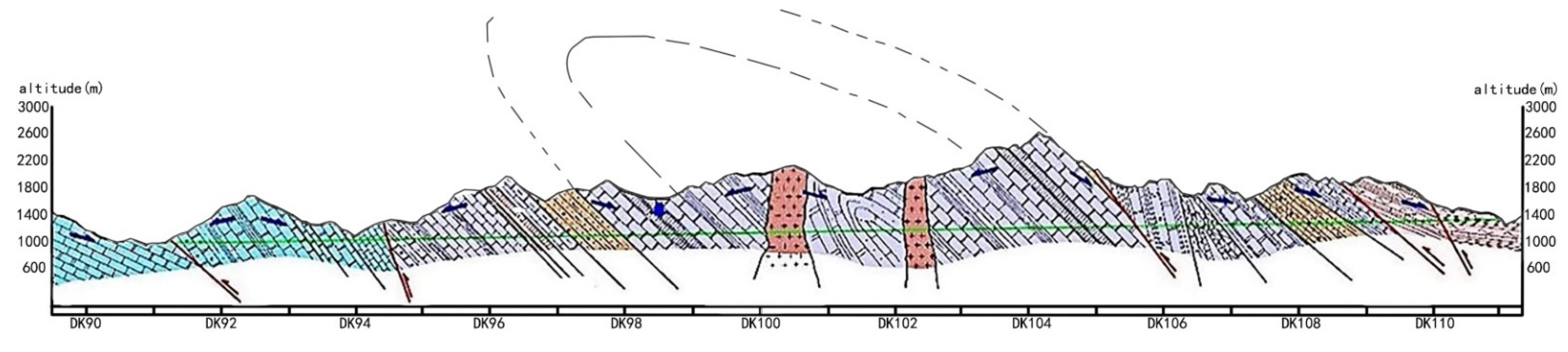
2. Project Overview
3. Numerical Model and Physical–Mechanical Parameters
3.1. Ubiquitous Joint Model
3.1.1. Elasticity
3.1.2. Yield Criterion for the Weak Plane
3.2. Mechanical Parameters of Numerical Simulation
4. Engineering Application
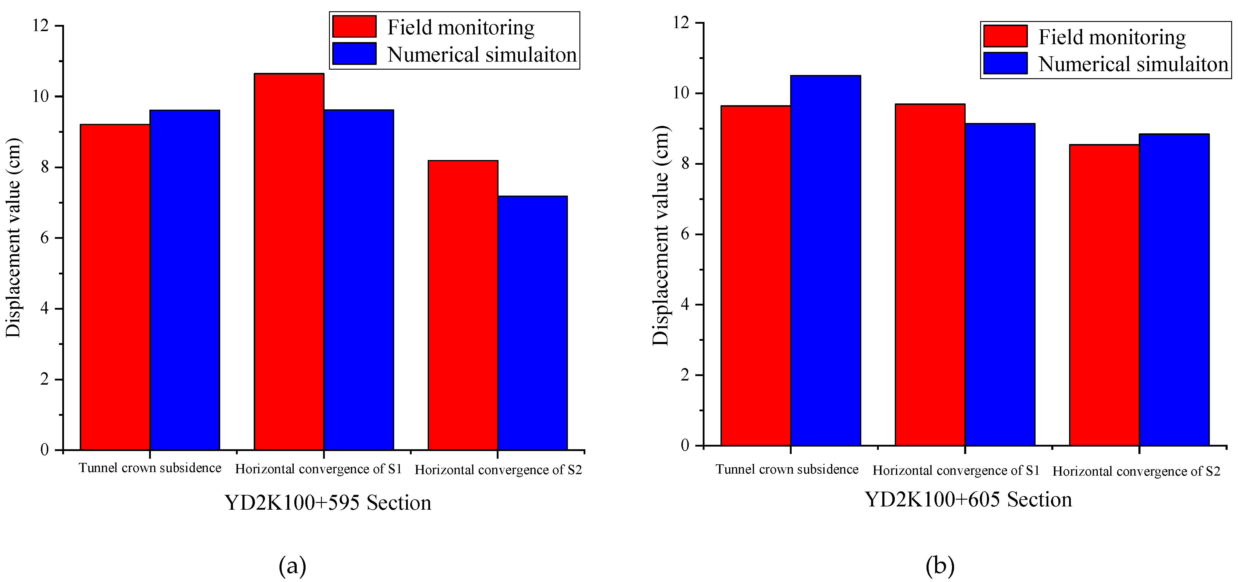
4.1. Comparison of Measurements and Simulation Results
4.2. Comparison of Measurements and Simulation Results
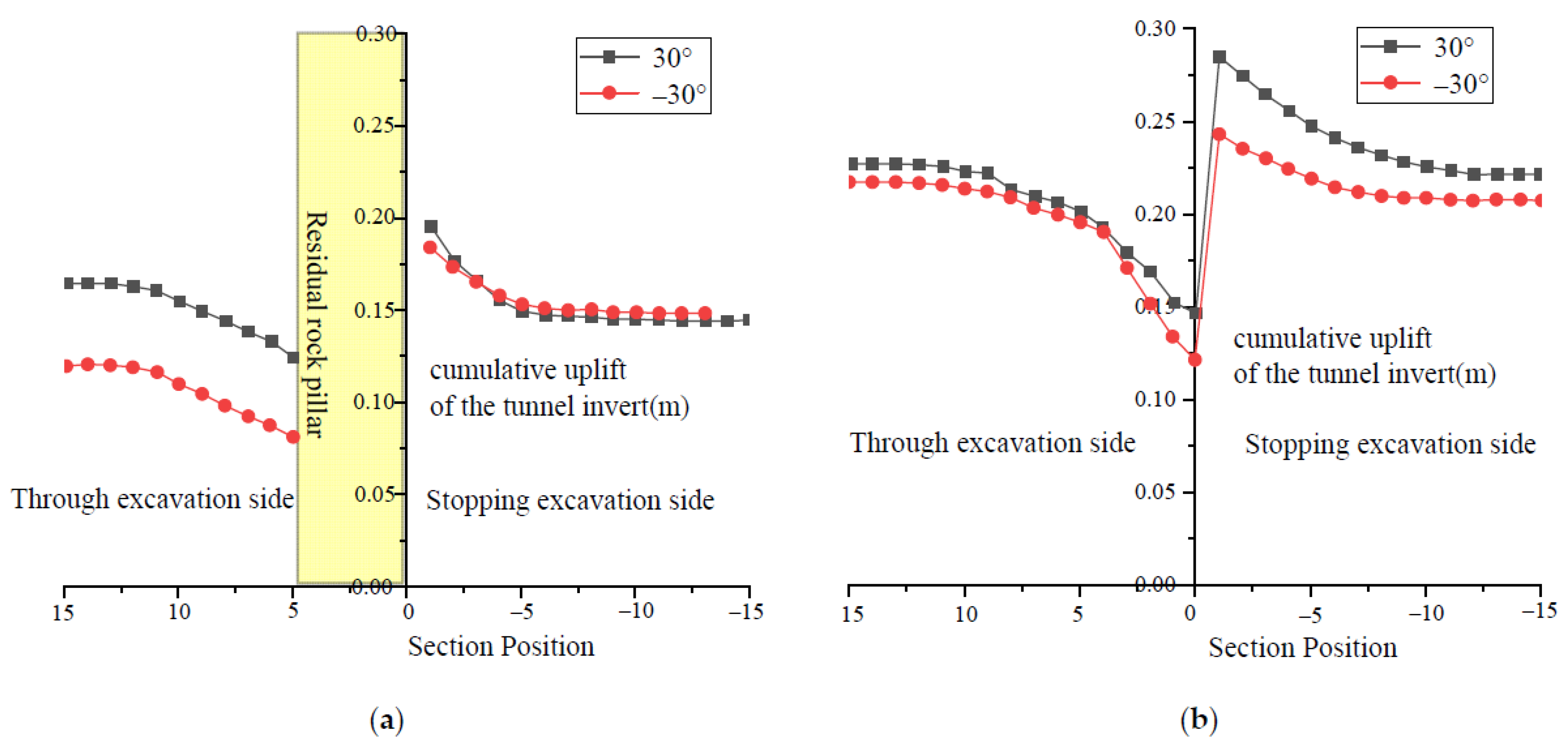
4.3. Comparative Analysis of the Tunnel Excavation of CIS and Inverse Layers in Gently Inclined Surrounding Rocks
5. Conclusions
Author Contributions
Funding
Institutional Review Board Statement
Informed Consent Statement
Data Availability Statement
Acknowledgments
Conflicts of Interest
References
- Luo, Y.; Chen, J.; Deng, X. Mechanical Model Calculations of Tunnel Roof with Horizontal Stratified Rock Mass Tunneling Considering the Interlayer Cohesion. China J. Highw. Transp. 2018, 31, 230–237. (In Chinese) [Google Scholar]
- Tao, Z.; Luo, S.; He, M. Analysis of Deformation Law and Creep Characteristics of Carbonaceous Slate in Highway Tunnel. J. China Univ. Min. Technol. 2020, 49, 898–906. (In Chinese) [Google Scholar]
- Wu, Y.; Tan, Z.; Li, S. Experimental Study on the Basic Characteristics of Tunnel in Squeezing Surrounding Rock with Large Deformation. China Civ. Eng. J. 2015, 48, 398–402. (In Chinese) [Google Scholar]
- Lekhnitskii, S.G. Theory of Elasticity of an Anisotropic Elastic Body. Phys. Today 1964, 17, 84. [Google Scholar] [CrossRef]
- Du, S.G.; Du, K.Q. Scale effect on the anisotropy characteristics of rock joint roughness. Q. J. Eng. Geol. Hydrogeol. 2021, 54, qjegh2020-066. [Google Scholar] [CrossRef]
- Ge, Z.; Pan, S.; Liu, J. Estimation of Brittleness and Anisotropy Parameters in Transversely Isotropic Media With Vertical Axis of Symmetry. IEEE Trans. Geosci. Remote Sens. 2021, 60, 1–9. [Google Scholar] [CrossRef]
- Huang, H.; Yu, Y.; Yang, C. Research on the Deformation Regularity and Treatment Measures of Tunnel Floor Heave in Gently Inclined Layered Surrounding Rock. J. Railw. Eng. Soc. 2021, 38, 72–78. [Google Scholar]
- Sui, J.; Ren, F.; Cao, J. Numerical Analysis for the Caving Characteristics of Rock Mass with Inclined Joints in Caving Mining. Adv. Civ. Eng. 2021, 2021, 9917744. [Google Scholar] [CrossRef]
- Tan, Z.; Li, S.; Yang, Y. Large Deformation Characteristics and Controlling Measures of Steeply Inclined and Layered Soft Rock of Tunnels in Plate Suture Zones. J. Eng. Fail. Analysis 2022, 131, 105831. [Google Scholar] [CrossRef]
- Wang, M.; Tan, Z. The construct technology of tunnel and underground engineering in China. Strateg. Study CAE 2010, 12, 4–10. (In Chinese) [Google Scholar]
- Wen, J. Study on Deformation Features and Control Measures of 3# Inclined Shaft in Yuelongmen Tunnel of Chenglan Railway; Chengdu University of Technology: Chengdu, China, 2017; pp. 9–11. [Google Scholar]
- Zhang, C. The Influence of Bedding Plane on Opposite Through Construction Safety of Long Tunnel; Beijing Jiaotong University: Beijing, China, 2021; pp. 20–21. [Google Scholar]
- Zhang, Q.; Jiang, A.; Wu, H. Research on Optimization of Tunnel Cyclic Advance Rate Based on Ubiquitous Joint Model. Mod. Tunn. Technol. 2020, 57, 70–77. (In Chinese) [Google Scholar]
- Luo, F.; Zhou, X. Analysis of Influence Factors on the Stability of Bedding Slope Based on Joint Model. Railw. Stand. Des. 2017, 61, 141–146. (In Chinese) [Google Scholar]
- Wang, Y.; Zhang, Y.; Feng, X. Model Test and Numerical Simulation of Surrounding Rock Stability of Chambers with Different Inclination Angles. Sci. Technol. Eng. 2019, 19, 281–287. (In Chinese) [Google Scholar]
- Zhao, Y.; Yang, T. Stability Analysis of Deep Buried Tunnel based on Ubiquitous-joint. Mine Met. Mine 2016, 45, 36–41. (In Chinese) [Google Scholar]
- China’s Railway Tunnel Design Code (TB10003-2016); China Railway Press: Beijing, China, 2017.
- Sainsbury, B.L.; Sainsbury, D.P. Practical Use of the Ubiquitous-Joint Constitutive Model for the Simulation of Anisotropic Rock Masses. Rock Mech. Rock Eng. 2017, 50, 1507–1528. [Google Scholar] [CrossRef]
- Song, D.; Huang, J.; Liu, X. Dynamic Response of Layered Rock Slopes under Earthquakes. J. Hunan Univ. Nat. Sci. 2021, 48, 113–120. [Google Scholar]
- Sainsbury, D.P.; Sainsbury, B.L.; Limited, C.G. Three-Dimensional Analysis of Pit Slope Stability in Anisotropic Rock Masses. In Proceedings of the Slope Stability 2013, Brisbane, Australia, 1 January 2013. [Google Scholar]
- Chang, L.S.; Chen, Y.N.; Tao, D.H. Numerical analysis of layered rock slop based on FLAC Ubiquitous-Joint model. China Min. Mag. 2013, 22, 77–80. [Google Scholar]


| μ | E (GPa) | Φ (°) | T (MPa) | C (MPa) | Jϕ (°) | Jc (MPa) | Jt (MPa) |
|---|---|---|---|---|---|---|---|
| 0.3 | 1.08 | 30° | 0.1 | 1.56 | 27 | 0.1 | 0.05 |
| μ | E (GPa) | Φ (°) | C |
|---|---|---|---|
| 0.2 | 21 | 35 | 9.37 |
| Dip Angle | Ways of Penetration |
|---|---|
| 0° |  |
| 30° |  |
| 60° |  |
| 90° |  |
| Dip Angle | Settlement of Vault (cm) | |||
|---|---|---|---|---|
| Through Construction Side (y = 3 m) | Stopping Construction Side (y = −3 m) | Difference | Relative Difference | |
| 0° | 16.5 | 26.7 | 10.2 | 61.82% |
| 30° | 9.82 | 19.5 | 9.68 | 98.57% |
| 60° | 7.54 | 13.3 | 5.76 | 76.39% |
| 90° | 7.92 | 13.6 | 5.68 | 71.72% |
| Dip Angle | Ways of Penetration |
|---|---|
| 30° (inverse layer) |  |
| −30° (CIS layer) |  |
Publisher’s Note: MDPI stays neutral with regard to jurisdictional claims in published maps and institutional affiliations. |
© 2022 by the authors. Licensee MDPI, Basel, Switzerland. This article is an open access article distributed under the terms and conditions of the Creative Commons Attribution (CC BY) license (https://creativecommons.org/licenses/by/4.0/).
Share and Cite
Gao, Z.; Luo, J.; Wu, X.; Li, K. Deformation Analysis of the Rock Surrounding a Tunnel Excavated through a Gently Dipping Bed. Appl. Sci. 2022, 12, 1960. https://doi.org/10.3390/app12041960
Gao Z, Luo J, Wu X, Li K. Deformation Analysis of the Rock Surrounding a Tunnel Excavated through a Gently Dipping Bed. Applied Sciences. 2022; 12(4):1960. https://doi.org/10.3390/app12041960
Chicago/Turabian StyleGao, Zhen, Jianjun Luo, Xu Wu, and Ke Li. 2022. "Deformation Analysis of the Rock Surrounding a Tunnel Excavated through a Gently Dipping Bed" Applied Sciences 12, no. 4: 1960. https://doi.org/10.3390/app12041960