1. Introduction
The necessity for increasing the efficiency of deployment of autonomous or hybrid unmanned underwater vehicles (UUV) with multilink manipulators (MM) for surveying large areas, detecting marine objects and performing manipulative operations with them has spurred the development of a multilevel system that would provide control over complex dynamic objects. The operation of robotic vehicles with such a system does not require a special support vessel or numerous maintenance personnel; additionally, their movements are not limited to the length of the umbilical cable, and they can travel dozens of kilometers in search of target objects [
1,
2,
3]. A MM mounted on an UUV significantly extends the range of its functional capabilities to also include sediment sampling from specified areas, collection of marine organisms, installation of beacons and various equipment and their cleaning and maintenance [
3,
4,
5,
6].
Researchers have designed a number of methods and algorithms for automating various manipulative operations of UUV. As shown in
Figure 1, these methods can be divided into a few major groups.
The methods explained in the studies [
7,
8] provide an evaluation of the roughness of the bottom topography in the working area and make a decision as to whether the bottom is suitable for safe manipulation by the time the UUV approaches the object. Their efficiency has been confirmed experimentally. Prior to the operations, the object is identified on the basis of data received from the onboard sonars [
9,
10], and then the UUV is sent to the object. Simultaneously, a site for stabilized hovering of the UUV is selected in such a way that the working zone of the manipulator allows correct execution of the required operations and avoidance of collisions of the vehicle with the bottom or object [
8].
Efficient methods have been developed to keep the UUV in the hovering (or dynamic positioning) mode near the object [
11,
12,
13,
14] using the vehicle’s thrusters, these methods provide compensation for the negative dynamic effects from unknown underwater currents and from the working manipulator. In this case, the force and torque effects from the MM are calculated in real time mode by the algorithm for solving the inverse dynamics problem (IDP) for underwater MM [
13]. The parameters of manipulator links’ interaction with the aquatic environment included in this algorithm are determined experimentally by the method [
15].
The shape and location of the target object relative to the UUV are determined with high accuracy using the data received from the multibeam echosounder sonars and stereo cameras, which constitute an onboard machine vision system (MVS) [
16,
17,
18]. Various MVS that produce output data in the form of point clouds have long and widely been used in both industrial and mobile robotics [
19]. The major advantages of such systems are the high-speed response, high accuracy and high scanning density, which allow reconstructing a 3D model of the workspace on the vehicles’ onboard computer. However, the underwater environment somewhat restricts the use of laser scanners or stereo cameras as MVS, due to optical distortions and possible high turbidity of the water. Nevertheless, with special algorithms for filtering and processing distorted information applied, optical MVS can also be used underwater [
20]. Before processing the obtained point clouds, the photo and video images pass through an image processing system [
21,
22]. The latter makes it possible to recognize the object with approximately known dimensions and color in an obtained image using special color filters. This significantly accelerates the process of search and identification of a previously known object by devices with lower computing capacities.
To build trajectories of movements of the MM working tool, special methods are required for various manipulative operations over the bottom surface and certain objects with already known shapes [
8,
18,
23,
24,
25]. These methods take into account the positions of the object’s surface, the MM’s working zone and the angle of approach to the object relative to each other. In particular, the method [
25] allows building complex spatial trajectories of the MM working tool on the object surface using point clouds obtained from MVS. However, it is unsuitable for automated manipulations, since the type of trajectory and its location on the object are determined by the operator and set by pointing the UUV camera optical axis.
The MM working tool should execute the programmed trajectories with specified accuracy. This necessitates using the method [
26] that, thanks to the introduction of self-adjusting correction devices (SCD) of the manipulator’s electric drives, compensates for the negative interactions between all its degrees of freedom that occur during movement at a high speed in the aquatic environment, and also for the coulomb and viscous friction torques in the drives. These interactions are calculated by the recurrent algorithm for solving IDP [
13]. The introduction of additional observers provides identification of unknown external torques on the shafts of the respective electric drives.
During a manipulative operation, the UUV inevitably, although slightly, shifts from its initial position, even if a system of stabilization in the hovering mode is used [
11,
12,
13,
14]. As a result, the MM working tool deviates from the programmed trajectories, thus, reducing the operation accuracy. To maintain the specified accuracy in the work [
27], a method for continuous automatic correction of programmed trajectories of MM’s movements is proposed, which takes into account actual displacements of UUV relative to its initial position.
When the MM grips a massive object, the UUV acquires undesirable list and trim angles under the effect of its weight. A lot of studies have addressed the issue of controlling movements of UUV exposed to external disturbances ([
11,
28], etc.). In particular, a method has been proposed in the work [
28], which allows adjustment of thrusters’ propulsions depending on the information about the difference between the programmed and current UUV movement vectors that come from a gyroscope and a Doppler velocity log.
An analysis of the above-mentioned methods and algorithms shows that a substantial basis has already been created for synthesizing an efficient multilevel control system of UUV to perform automatic manipulative operations. However, the known methods for determining the shape and location of an object relative to UUV have a number of disadvantages that restrict the range of their applications. In particular, the method [
18] suggests alignment of the point clouds received from MVS with the clouds formed on the basis of previously constructed 3D models of the object. However, the point clouds of the scanned object obtained in the model were evenly distributed over the object’s surface, which is impossible in actual conditions due to unidirectional scanning. Furthermore, the alignment of the point cloud of the constructed model with that of the actual object scanned needs to be tested for accuracy. A decision about the further execution of the trajectory built on the object’s surface should be made on the basis of the test results. However, when forming desired trajectories of the MM working tool, this method does not take into account the probability of silting, fouling and deformation of the object, which can negatively affect the accuracy of manipulative operations.
In this article, we propose an upgrade of the method [
18] to eliminate these weaknesses. Based on this method for manipulations over an object (
Figure 1), as well as on the previously considered ones [
13,
15,
18,
26,
27], a goal is set to synthesize, implement and study, through numerical modeling, a control system of UUV that would provide accurate automatic manipulative operations.
2. Improving the Accuracy of Determination of Work Object’s Shape and Location
As noted in the Introduction, the high-accuracy determination of the shape and location of an object relative to UUV is carried out in the stabilized hovering mode [
11,
12,
13,
14]. The undersea surroundings are scanned by the MVS units [
16,
17] to form clouds of points distributed over the bottom and object surfaces. The point clouds are set in a rectangular coordinate system (CS)
Oxyz rigidly fixed to the UUV hull, with the origin located at the center of buoyancy of the vehicle, the
Ox axis coincides with the horizontal, longitudinal axis of the UUV, the
Oz axis coincides with its vertical axis and is directed downward, and the
Oy axis complements the other two axes to form the right-hand CS.
To identify a certain known object in the point cloud obtained from MVS, the work [
18] suggests using a 3D model of this object, preprocessed and transformed into a point cloud set in the CS
Oxyz. This cloud, consisting of
m points
(
), first, is virtually approximated to the cloud of points belonging to the actual object through the linear transfer in the direction of the vector
, whose magnitude and direction are determined by the systems of detection of underwater objects that stand out from the surrounding [
9,
10]. Then the displaced cloud, defined by the points
, is aligned with the point cloud of the object using the iterative closest point (ICP) algorithm [
29] implemented in the open-access Point Cloud Library (PCL) [
30].
In the case the point clouds are aligned by the standard PCL tools (see
Figure 2), the vector
and the matrix
are calculated. These are required for the cloud alignment as they describe, respectively, the linear displacement and rotation of the model point cloud relative to the axes of the CS
. Consequently, for any point
belonging to the point cloud of the object model, a point
can be obtained that defines the position of the point
after the two clouds are aligned [
18]:
where
is the midpoint (center of mass) of the point cloud of the object model, and
is the vector that defines the position of any point
relative to the point
of this cloud.
Accuracy of cloud alignment is evaluated by the method of least squares for the nearest points of these clouds at each iteration of the ICP algorithm. Therefore, the presence of “excess” points in the displaced object model (which are absent from the scan of the actual object due to the unidirectional scanning by MVS) often causes errors in alignment of the centers of mass of the two clouds. Nevertheless, studies have shown that correct spatial orientation of the object model’s cloud is usually achieved even in such cases (
Figure 2).
To increase accuracy of the point clouds alignment, some of the points
of the object model lying on the surface of this model and invisible to MVS should be discarded. Thus, we assume that a preliminary alignment of clouds allows setting a spatial orientation of the object model that would match quite precisely the orientation of the actual object. To do this, for each point
, calculate the angle
lying between the normal vector
, connecting the center of mass of the cloud
with the point
, and the vector
, where
S are the coordinates of the CS origin of MVS in the CS
Oxyz. Discard the points
for which the inequality
is true (
Figure 3).
After discarding the excess points, the clouds are aligned again by the ICP algorithm, and the vector
and matrix
are calculated that describe the subsequent linear displacement and rotation of the model’s point cloud relative to the SC
. As a result, similarly to Equation (1), the coordinates of the points
of the aligned point cloud of the object model are found by the following expression:
3. Testing the Accuracy of Point Clouds’ Alignment and Building the Trajectories of Movement of MM Working Tool over Object Surfaces
To test the accuracy of the point clouds’ alignment performed, it is suggested to compare two projections of the same test trajectory: a projection onto the triangulation surface of the scanned object and a projection of this trajectory onto the triangulation surface of the object model aligned. To do this, the point cloud
and the point cloud of the object obtained from MVS should be represented as triangulation surfaces [
17,
31] consisting of a multitude of triangular polygons, where adjacent ones have common edges and vertices. In the CS
, each triangle of the object model surface is defined by a set of three vertices
, where
,
g is the number of triangles, and each of the
w triangles of the scanned object surface is defined by vertices
.
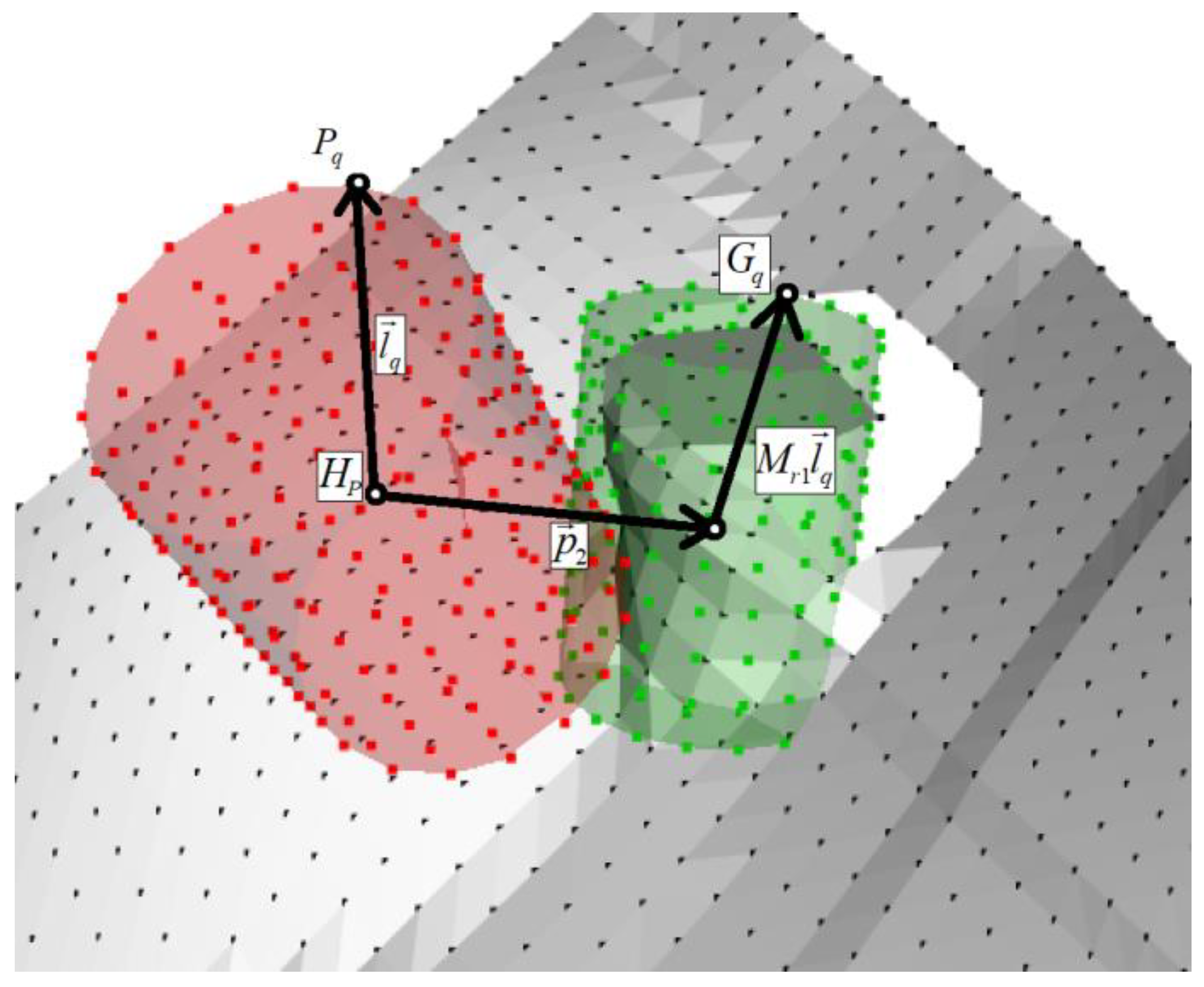
To project the test trajectory built in the CS
onto both triangulation surfaces, it is necessary, first, to define the direction of the projecting rays by a single vector
from the point
S of the CS origin of MVS to the center of mass
of the object model’s point cloud (
Figure 4). The test trajectory should run on a plane perpendicular to the vector
, and its configuration can be selected depending on the known dimensions and shape of the object. As an example, define the trajectory as a sequence of
n points lying on the same straight line
,
and find intersections of the rays extending from these points in the direction of the vector
with both triangulation surfaces (
Figure 4).
As a result of the intersections, sets of points and are formed, which are the projections of the test trajectory onto the surfaces of the actual and simulated objects, respectively.
The coordinates of the points
and
can be calculated using the modified Möller–Trumbore algorithm [
25] in the following form:
where (·) is the scalar product of vectors; (×) is the vector product of vectors.
The trajectory projections consist only of the coordinates of the points and and, therefore, they can be transmitted to the operator’s control console even via a hydroacoustic communication channel with a low bandwidth. The operator can visually evaluate the locations of these trajectories relative to each other, and then either confirm execution of the manipulative operation or give a command to re-scan and re-align the clouds.
For a UUV having no communication channel with its operator, criteria should be set out to evaluate adequacy of the previously performed alignment. Standard deviation of the coordinates of the projected trajectories’ points can be used as such a criterion:
,
(
Figure 5).
The threshold value of the criterion Q depends on the dimensions of the object and the resolving power of MVS. Studies have shown that the threshold value for the simulated MVS and object is ; if it is exceeded, the alignment can be considered erroneous. In this example of successful alignment of point clouds, the value amounts to .
When the performed test shows that the object model’s point cloud is precisely aligned with the object’s cloud, the trajectory of the MM working tool built on the original object model can be transferred to the actual object. This trajectory can be initially defined both in an analytical form and as a sequence of points
(
where
s is the number of points) with the respective single vectors
and
defining the desired orientation of the working tool at the
jth point. With Equation (2) taken into account, the trajectory transferred to an actual object can be expressed as follows:
where
Xj are the points with the respective orientation vectors
and
that define the desired positions of the MM working tool on the object surface, and
is the center of mass of the object model’s cloud of initial points
.
In cases where the exact shape of an object cannot be known in advance, or there is a high probability of its deformation, fouling or silting, the desired trajectory of the MM working tool (4) can additionally be projected onto the triangulation surface of this object constructed using MVS. To do this, similarly to Equation (3), points
Xj are projected in the positive and negative directions of the vector
, because these points can be located both outside and inside the triangulation surface of the object. As a result, a sequence of
Tj points is formed to be located on the surface of the actual object:
To provide smooth movements of the MM working tool along the trajectory, the sequences of points
Xj or
Tj can be smoothed by parametric 3rd-order B-splines using the algorithm [
32].
4. Software-Based Implementation of the System and the Mathematical Models of UUV and MM
The above-considered upgraded methods for processing sensor-derived information and building trajectories of a MM working tool were implemented in the C++ programming language. The created program makes it possible to build triangulation models of surfaces of seafloor objects by the algorithm [
31]. The input data for the program are a multitude of points lying on the bottom and object surfaces obtained using MVS, and also the point cloud of the object model. Based on the input data, the program starts a cycle (iterations) of object identification and, as a result, values of
are determined. Then the alignment of point clouds is tested, and, in case of successful identification of the object, the program transfers the sequence of points
pre-set in the CS
and their respective vectors
and
onto the surface of the actual object.
A graphical interface using PCL has been created to display and test alignment of point clouds and build MM working tool trajectories (
Figure 6). Using visual information, the operator can additionally evaluate the results of the system operation.
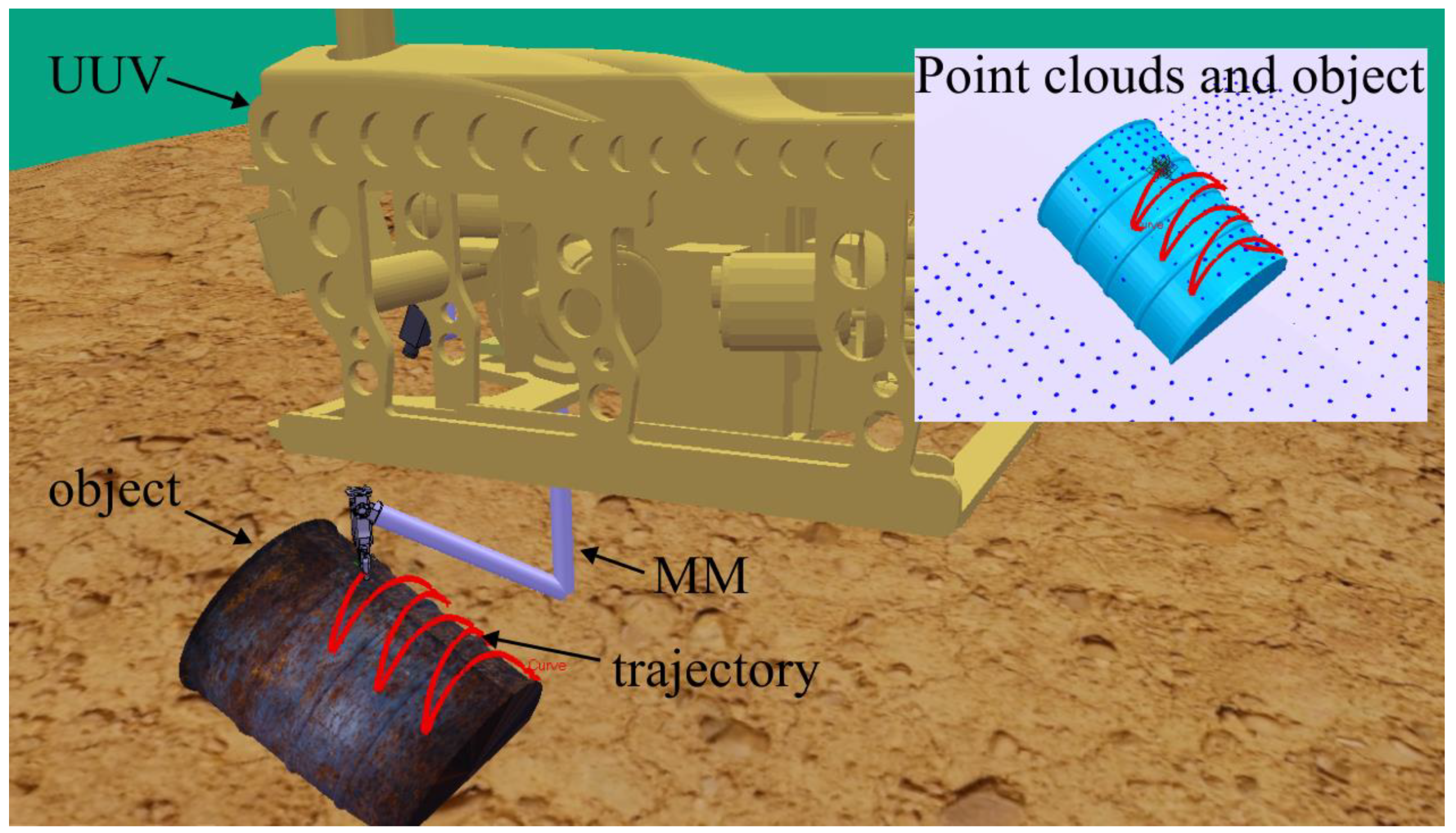
A system operability test was performed through numerical simulation in the virtual environment of the V-Rep robot simulation software. A scene of one manipulative operation to clean an object from fouling is shown in
Figure 7. As MVS, we used a model of multibeam echosounder sonar with a resolution of 32 × 32 dots and unidirectional scanning. This resolution is sufficient to perform operations with the target object. The sequence of points
(or
) and their respective vectors
and
of the MM working tool, formed by the software, were smoothed by parametric 3rd-order B-splines [
32] and sent to the Matlab/Simulink software package via the TCP protocol. The programmed signals to control the MM electric drives of the respective degrees of freedom were formed on the basis of these sequences.
In the simulation, we used the well-tested mathematical model of UUV [
33] and MM with the PUMA kinematic scheme having the first five degrees of freedom (three in translation and two in orientation). The basic parameters of the UUV and the manipulator are shown in
Table 1. A complete list of parameters of the UUV model is provided in the works [
34,
35]. The MM model used and its parameters are described in detail in [
26]. This model includes a recurrent algorithm for solving IDP [
13], which takes into account not only mutual influences in the MM degrees of freedom, but also specifics of the effect of a viscous fluid on the moving links of MM and the experimentally determined parameters of this effect [
15]. The MM attachment point in the SC
had coordinates
M = (0.6, 0.6, 0.45)
T (
Figure 7).
In our work, we used the dynamic models of UUV and MM implemented in Matlab/Simulink. Therefore, in order to simplify interactions of the subsystems included in the created multilevel control system of UUV (
Figure 1), the methods for stabilizing the UUV in the hovering mode near the object, controlling its movements and correcting the MM working tool trajectory, with undesirable displacements of the UUV taken into account, were also implemented in Matlab/Simulink.
To stabilize the UUV in the hovering mode, we used a combined system [
13,
14] that provides compensation for the effect of sea currents and the dynamic effects of the moving manipulator, calculated in real time, using the propulsion thrusters of the vehicle. To maintain the specified accuracy of MM working tool’s movement along the trajectory in conditions of small but unavoidable displacements of the UUV in the stabilization mode, the method [
27] was implemented in the system. On the basis of information about linear and angular displacements of the UUV from the initial position, this method allows finding coordinates of the vector
that defines the current desired position of the MM working tool on the object surface in the CS
Oxyz as follows:
is the matrix of rotations of the CS
Oxyz relative to the absolute CS, calculated taking into account the directions of its axes;
S() =
sin();
C() =
cos();
are the roll, yaw and pitch angles of the UUV, respectively;
is the vector defining linear displacements of the UUV in the absolute CS;
is the vector defining the current desired position of the working tool’s characteristic point in the CS
Oxyz.
To provide accurate movements of the working tool along programmed trajectories, SCD [
26] have been synthesized. These SCD generate control signals of the MM electric drives taking into account the estimated external torques in the respective drives, and also the variations in the viscous and coulomb friction torques in the drives that are identified by the additional observers.
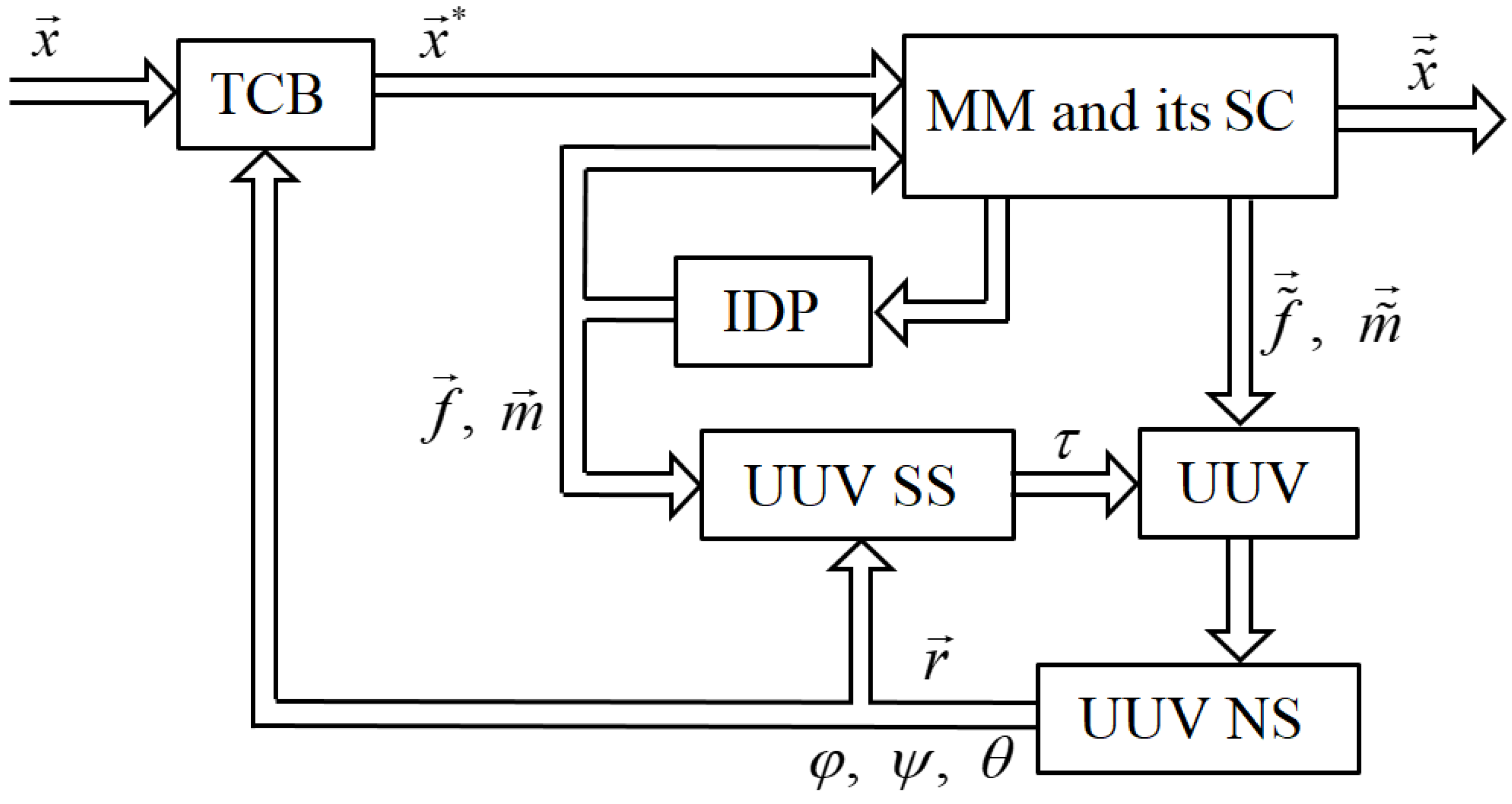
Figure 8 shows a block diagram of the subsystem for the dynamic control of movements of an UUV and its manipulator implemented in Matlab/Simulink. The acronyms used in the figure are as follows: TCB is the block for correcting the trajectory of the MM working tool [
27]; MM and its SC are the model for the manipulator and the system of its control [
26];
,
are the vectors of, respectively, force and torque effects of the manipulator on the UUV calculated by the IDP solving block [
13]; UUV SS is the stabilization system [
13] that forms the resulting vector of thrusts and torques
created by the UUV thrusters to compensate for the vectors of the force
and torque
effects from the manipulator; UUV NS is the navigation system of the UUV;
is the vector of the actual position of the MM working tool in the CS
Oxyz.
5. Results of Numerical Modeling
When determining the work object’s shape and location, we compared the results of using the standard ICP algorithm with those of the proposed method based on discarding points invisible to the sonar. The quality of alignment of the point clouds for these two cases was tested by projecting the test trajectory onto the triangulation surfaces of the object and its model (
Figure 9). This trajectory consisted of a set of points
,
spaced at 0.01 m intervals along two perpendicular straight lines lying in a plane perpendicular to the vector
. The directions of these straight lines were defined by the vectors
:
Then we found the intersections of the rays extending from the points
in the direction of the vector
with both triangulation surfaces (
Figure 9) using Equation (3). An assessment of the accuracy of point clouds alignment showed values
and
, respectively, for the standard ICP algorithm and the proposed method. According to this assessment criterion, the accuracy increased 7-fold.
A sinusoidal trajectory with an amplitude of 0.2 m was preliminarily overlaid on the object model (
Figure 7). After accurate identification of the object (
Figure 9), the trajectory was transferred to its surface and smoothed by 3rd-order B-splines (
Figure 10). The origins of the absolute CS and the CS
Oxyz were assumed to coincide with the initial moment of time (
). The MM working tool was moving at a constant speed of 0.3 m/s along the resulting trajectory; the total movement time was 8.4 s.
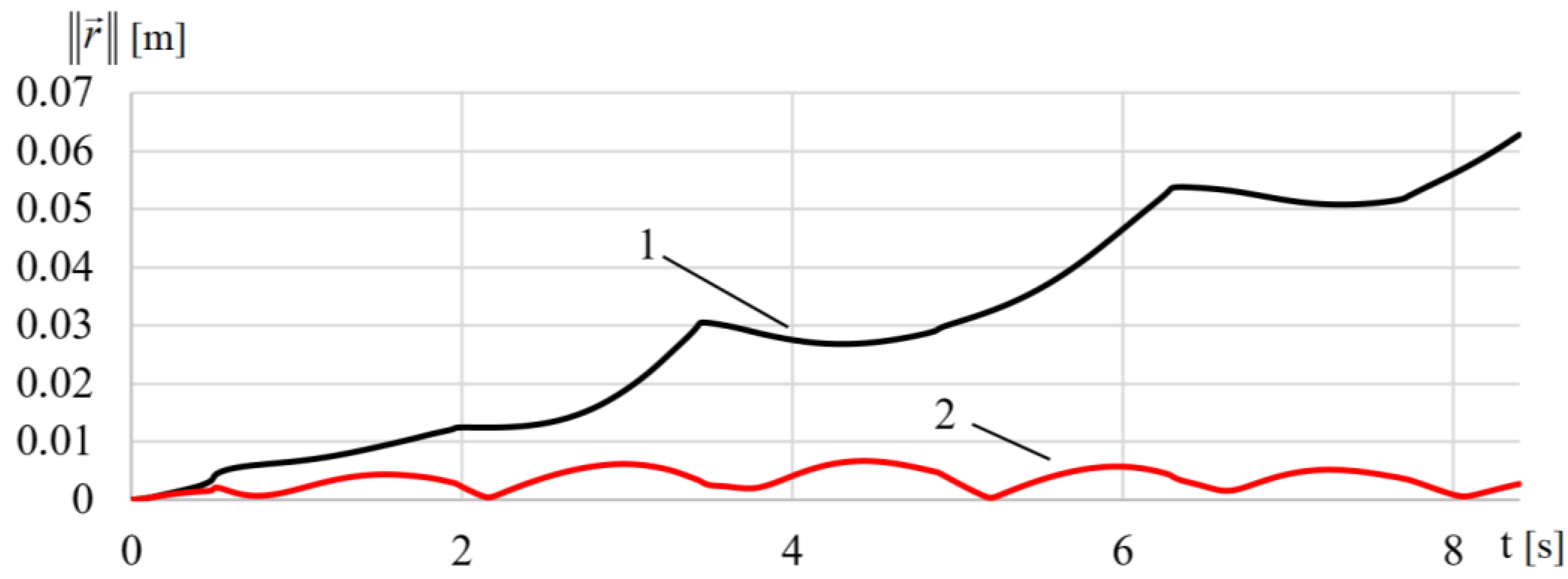
Figure 11 (curve 1) shows the Euclidean norm
of the vector
of the UUV’s linear displacement from the initial point when the working tool is moving along the programmed trajectory without the combined stabilization system; curve 2 represents values of the same parameter with this system employed. As can be seen from the figure, the introduction of a stabilization system allows accurately holding the UUV in a desired position near the object, which reduces unwanted UUV’s displacements from 65 mm to 7 mm. Thus, the deviation of the angular coordinates of the UUV without a dynamic positioning system reaches 0.05 rad; with this system used, the value is no greater than 0.015 rad.
Figure 12 shows graphs of variations in the Euclidean norm
of the vectors
of MM working tool’s deviations from a programmed trajectory in the absolute CS for three cases of simulation: without the UUV stabilization system (curve 1), with the UUV stabilization system employed (curve 2), and with the systems of UUV stabilization and correction of programmed working tool’s trajectories (curve 3). In the first case (
Figure 12, curve 1), the ε value reached 7 cm. After the introduction of the UUV stabilization system, the ε values were no greater than 2 cm (
Figure 12, curve 2). The use of an additional correction of programmed working tool’s trajectories (
Figure 12, curve 3) reduced deviations almost 10-fold in most segments of the trajectory. However, in curved segments, where the pattern of manipulator links’ movements changed, the ε value reached 1 cm for a short time due to an increase in the dynamic error of tracking the working tool along the trajectory. With the synthesized SCD of the MM drives employed, the error was no greater than 9 mm in the CS of the MM.
Thus, the results of numerical simulation have confirmed the operability of the synthesized system that provides high accuracy of operations executed by the MM working tool of a UUV in the automatic mode. Stable functioning of the dynamic control subsystem (
Figure 9) is provided by known and well-tested methods and algorithms [
13,
26,
27]. These systems allow quite efficient compensation of external disturbing effects on the accuracy of UUV stabilization and MM operation.
It should be noted that the synthesized system needs geometric shapes of target objects to be known prior to the operation. However, for many manipulative operations, this is much easier than setting special markers on an object in advance, as suggested in [
22]. Unlike the known methods based on image processing [
4,
21], the proposed system allows accurate identification of objects that are subject to silting, fouling and deformation. Furthermore, MM trajectories can be built even on the surfaces of objects invisible to the sonar.
As compared to the method [
25], which uses point clouds to identify objects in a similar way, the synthesized system makes it possible to perform operations that do not require an operator’s intervention. A significant advantage of the system is also the opportunity to use the underwater acoustic channel of communication with the UUV to transmit to the operator the information necessary for assessing the accuracy of object identification and building the MM trajectories to the operator.


