1. Introduction
Within the framework of EUROfusion project, the Water-Cooled Lithium-Lead (WCLL) is one of the two Breeding Blanket (BB) concepts selected for the EU DEMO reactor and one of the Test Blanket Module concepts to be qualified in ITER reactor. In order to reduce the tritium permeation from the breeder, i.e., the eutectic alloy LiPb (15.7 at.% Li), into the water coolant, a dedicated R&D activity on antipermeation coatings was carried out to select the most promising technologies to be applied in the BB [
1]. The development of antipermeation and corrosion barriers may have an impact on the WCLL BB design, in particular in the capture of the system requirements as well as in the assessment and definition of its interface with the primary heat transfer system, water detritiation system and/or LiPb loop. In fact, thermal-hydraulic, safety and manufacturing aspects have to be taken into account, among the others, when introducing coatings [
2,
3]. In 2014–2020, three Al
2O
3-coatings against tritium permeation, corrosion and as electrical insulation were developed at a laboratory scale, and a preliminary scaling-up of the technologies was performed. The currently investigated fabrication technologies are PLD (Pulsed Laser Deposition), ECX (electro-chemical deposition) and ALD (Atomic Layer Deposition) [
4]. The coating technologies were characterized from the point of view of the chemical compatibility in stagnant and flowing LiPb at 500 °C and of the capability to reduce the permeation flux and the electrical conductivity. The latter is necessary in order to reduce the pressure drops generated by the Magneto-Hydro-Dynamic (MHD) effect across the BB. These analyses were necessary to assess their applicability to DEMO and ITER reactors. The three selected Al
2O
3-barriers developed at a laboratory scale have shown good performances in the experimental characterization (permeation tests with and without gamma rays and electron irradiation, corrosion tests and thermal cycle characterization), but further upgrades are needed to coat real geometries and components. In order to demonstrate the applicability to WCLL BB, where it is requested to coat about 40,000 m
2 of water pipes and BB internals and 3700 m of LiPb pipes with 10” diameter [
1,
4,
5], a mock-up of WCLL water pipes will be manufactured and characterised in flowing LiPb with the support of the experimental facility TRItium EXtraction-II (TRIEX-II) installed at ENEA Brasimone Research Center. The coating processes investigated will be PLD and ALD techniques. The mock-up is designed with the feature to substitute coated tubes, allowing to test different geometries and/or coating manufacturing techniques at relevant WCLL operative conditions.
The cost related to the PLD and ALD coatings manufacturing has been estimated taking into account 70% uptime and 80% productivity. The total cost of the layer deposition on the entire surface of a BB has been estimated to be about 300 k€. To this, it has to be added the capital investment (estimated to be about 1 M€ for PLD and 0.8 M€ for ALD) and the cost of manpower, considering about 3 years of work. In conclusion, the total cost due to the Al2O3 coating proved for the full reactor to be about 2.0 M€ for PLD and 1.8 M€ for ALD coating manufacturing.
2. Coating Technologies and Manufacturing Strategies
PLD [
3] is a thin film deposition technique in which the material to be deposited is evaporated from the source target through an intense laser pulse. A dense vapour of “ablated” material is deposited on the substrate placed in front of the target and, then, it is adsorbed until it forms the thin film. PLD characterization demonstrated the feasibility of the scaling-up of the PLD technique to coat WCLL water pipes and BB internals before the assembly, but it is not possible to coat complex geometry or welds. Therefore, it is planned to combine PLD technique with ALD, a Chemical Vapor Deposition (CVD) process that allows to coat all internals [
6]. The ALD is a technology for the growth of thin and ultra-thin films with a very accurate thickness control (of the order of 0.5 Å) and with high uniformity and conformity. These characteristics are obtained thanks to a deposition of individual atomic layers in succession. Moreover, one of the main advantage of PLD and ALD coating process is the deposition temperature lower than 200 °C that doesn’t affect the mechanical or microstructural properties of EUROFER welds.
Corrosion compatibility tests carried out with PLD and ALD techniques have not shown corrosion attack of EUROFER or coating degradation in static LiPb at 550 °C after 2000 h, 4000 h and 8000 h and in flowing LiPb at 0.5 m s
−1, 500 °C at 1000 h, 2000 h and 4000 h [
4]. In the frame of EUROfusion FP9 project, the coatings will be characterized up to 16,000 h in LiPb. Moreover, PLD coating has demonstrated to be able to reduce the tritium permeation flux on the EUROFER martensitic/ferritic steel substrate, the BB structural material, at least of a factor 10,000 under electron irradiation combined with thermal cycling and of more than 200 under neutron irradiation [
7,
8]. PLD coating, characterized in the temperature range between 20 °C and 450 °C, works also as electrical insulator, reducing the MHD effect. The main limitation of the PLD process is intrinsic to the technique, since it can only coat external surfaces. ALD technology is very promising in terms of capability to reduce tritium permeation flux and the possibility to be applied on complex geometries even at low temperature. Therefore, it is planned first to coat the pipes of the mock-up with PLD process, then to bend the tubes and to weld them with the support structure and finally to perform ALD coating inside the mock-up to cover all the welds.
In order to validate the quality of the coating manufactured in the TBM/BB a dedicated procedure was developed by IIT, the so called Electrochemical Quality Test (EQT): the EQT exploits the conductivity of the EUROFER and the high resistivity of the oxide coatings. The part is submerged in an electrolyte and by Electrical Impedance Spectroscopy (EIS) is possible to measure the resistance and capacitance of the system. By modelling the data, it is possible to extract an average defect density and coating resistivity on the whole coated component, even of complex shape, like a breeding blanket module.
3. WCLL BB Mock-Up Design
The designed mock-up reproduces a portion of the breeding zone of the WCLL BB [
9], where the water pipes will be externally coated to reduce both the tritium permeation from the breeder into the coolant and the corrosion rate of EUROFER. A summary of the main design parameters of the mock-up is reported in
Table 1.
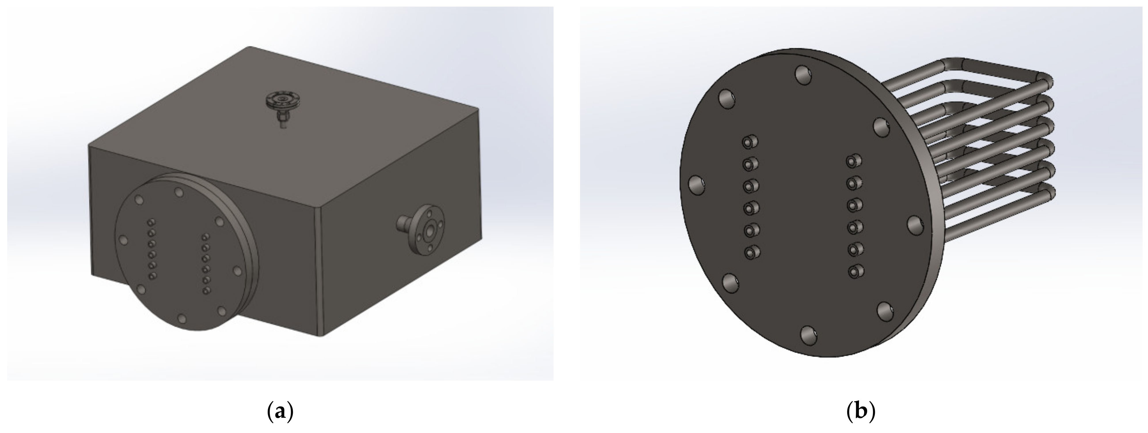
The mock-up (
Figure 1) will be installed in TRIEX-II facility, whose main characteristics are reported in
Section 4, and consists of 6 U-shaped EUROFER pipes installed in a dedicated stainless steel box, with a size of 600 × 600 × 300 mm
3. Each tube has an outer diameter of 13.5 mm, an inner diameter of 8 mm and a total length of 900 mm. The diameter and thickness of the tubes are the same as those used for the double-walled tubes (DWT) of the WCLL BB. One pipe is made of bare EUROFER to obtain the reference value of permeation flux to be used for the calculation of the permeation reduction factor (PRF), see Equation (1). The other 5 tubes will be PLD or ALD coated. The length of the tubes is limited by the maximum length to which the PLD process can be applied. The maximum possible length of the tubes was chosen to increase the permeation area as much as possible, so that it is possible to detect a hydrogen or deuterium flux (Q
2, Q=H, D). In fact, even if the PRF is independent on the permeation area, the measurement of the flux is carried out by a quadrupole mass spectrometer, which can provide the amount of permeated moles of hydrogen isotopes in the unit time (e.g., mol s
−1); in order to have a signal which can be measured by the mass spectrometer, a sufficient permeation area has to be guaranteed. The tubes are welded to a plate flanged to one side of the box for easy maintenance/replacement. This solution allows direct connection to the mass spectrometer and avoids bends that interfere with vacuum pumping. All the internal parts of the box will be coated by ALD. The coating characterization will be performed in gas phase, in the first part of the experimental campaign, and LiPb in the second part of the characterization. Hydrogen or deuterium are used instead of tritium and will be dissolved in the liquid metal at the appropriate partial pressure (10–1000 Pa) through the saturator column S200 of TRIEX-II, as detailed in
Section 4. The tubes are connected to a mass spectrometer to measure the amount of hydrogen permeated from the box.
In
Figure 2, the Process Flow Diagram (PFD) of the mock-up is displayed. It is constituted by the following main subsystems:
Subsystem 100 (test section);
Subsystem 200 (LiPb interface system);
Subsystem 300 (vacuum system);
Subsystem 400 (gas supply system).
The mock-up is constituted by the stainless steel flanged box, the HV gate valves (FV-09 to FV-20) and the capacitive vacuum meters (PT-03 to PT-08). The choice of capacitive pressure transducers relies on the need to guarantee high-accuracy measurements (0.15% of the measured values). The test section is heated by means of a dedicated heating system. A set of K-type thermocouples will be used to map the temperature in different points of the box and in the pipings (TT-01 to TT-10).
The LiPb system interfaces with TRIEX-II facility by means of two 1” pipes in P22 steel. The LiPb line (1” nominal diameter) can be intercepted by two ball valves, FV-07 and FV-08. The vacuum system consists of an integrated pumping station (diaphragm and turbomolecular) and its connections.
The VP-01 pumping station is needed to evacuate the test section only, whereas the U-shaped pipes can be backed out by means of the leak detector/mass spectrometer, which is equipped with a diaphragm and a turbomolecular pump. The vacuum expected in the test section is around 10−5–10−6 mbar. The vacuum system can be intercepted by the electropneumatic high-vacuum (HV) gate valve FV-05. The pressure of the system is read by two full range Pirani/Hot cathode pressure transducers, whereas the pressure reading in the selected mass spectrometer is a built-in feature.
Finally, the gas supply system is needed to provide inert gas to the test section. Hydrogen, deuterium and helium are the gases to be supplied in the correct mix during the experiments in gas phase. The gas line will be equipped with pressure reducers and a filter and it will be connected to the stainless steel box from the top. The filter will prevent LiPb dust contamination during the second experimental phase.
4. Integration in TRIEX-II Facility and Experimental Investigation
The mock-up will be installed in TRIEX-II facility, a LiPb loop for the characterization of tritium extraction technologies and technological solutions for the management of tritium balance in liquid metal for ITER and DEMO reactors.
The facility consists of an isothermal LiPb loop with a permanent magnet pump, a saturator, a Q extraction system from LiPb and instrumentation devoted to measure the Q concentration in LiPb and to measure the LiPb mass flow rate and pressure drops for each component. The new mock-up will be installed in the test section S300 replacing the current extractor based on the Gas-Liquid Contactor technology [
10].
The mock-up will be connected with TRIEX-II LiPb loop (
Figure 3) by means of two 1” pipes equipped with two ball valves to isolate the mock-up. The inlet of LiPb will be on one side of the box, while the outlet will be positioned on the bottom of the box to allow the gravity draining. The box will be equipped with a level meter, to control the filling with LiPb, and a pressure transducer to monitor the pressure when it is filled with gas. The saturator uses the Gas-Liquid Contactor technology, where a stream of helium with a variable Q
2 concentration is brought into contact with a counter-current stream of LiPb. By doing this, Q
2 diffuses from the gas to the liquid by concentration gradient. A Mellapak 452Y structured packing supplied by Sulzer is used in the saturator to increase the interface between the two phases, thus enhancing the hydrogen isotopes solubilization in the liquid lithium-lead. The mock-up will be tested at WCLL BB relevant conditions: LiPb temperature in the range between 330–500 °C and LiPb mass flow rate in the range between 0.5–4 kg/s.
The experimental campaign will be divided in two steps:
During the first phase, the ball valves in the LiPb lines (FV07 and FV08) are intercepted and only helium with a certain percentage of hydrogen or deuterium is injected. The hydrogen that permeates inside each pipe is measured through the mass spectrometer and the PRF can be calculated as:
where
is the flux permeated through the pristine EUROFER pipe and
is the flux permeated through one of the coated pipes. This definition of PRF corresponds to the so-called intrinsic PRF, i.e., the PRF evaluated for the coating applied on the whole surface of a given sample.
During the second phase, a known concentration of hydrogen or deuterium is solubilized in the LiPb by means of the TRIEX-II saturator (S200). The concentration of hydrogen in LiPb can be measured by three permeation sensors, installed upstream of the saturator, upstream and downstream of the test section [
11,
12]. Also in this case, the mass spectrometer will be used to detect the amount of hydrogen that will permeate into the different pipes of the mock-up.
5. Transport Analysis in Support of the Design
A hydrogen isotopes transport analysis was conducted with the aim of determining the permeation flux which is foreseen at a temperature of 330 °C and for a partial pressure varying from 10 to 1000 Pa. The simulations were performed taking into account tests in gas phase and tests in liquid phase, according to the two steps foreseen in the experimental campaign (see
Section 4). In order to have a first estimation of the permeation fluxes, a 1D approximation was considered. The main input data are reported in
Table 2. It has to be observed that the transport properties for LiPb come from in-house measurements carried out in HyPer-QuarCh II experimental device [
13]. The transport parameters of the martensitic steel OPTIFER-IVb (OIVb) [
14] were used, because of a lack of data for surface parameters of EUROFER in the literature.
5.1. Gas Phase Operation
The permeation of hydrogen through a membrane is called gas-driven permeation because the permeation is induced by the pressure gradient of the hydrogen gas between upstream (high-pressure side) and downstream (low-pressure side). This permeation is influenced by at least four factors: diffusivity, solubility, surface adsorption and desorption, and hydrogen-defect interaction. For the purposes of this study, the presence of structural defects or trapping sites is neglected, so it is possible to identify two limiting regimes: the Diffusion-Limited Regime (DLR) and the Surface-Limited Regime (SLR). The term
limited refers to the slowest process that dominates the process. The key parameter for identifying the regime condition is the permeation parameter
[
15]. It can be shown that in the case of permeation of a single isotope, for example hydrogen, the permeation parameter can be written as follows:
where
is the hydrogen partial pressure at the high-pressure side of the pipe. The permeation parameter is a property of the material through which permeation occurs. According to [
10], the intermediate regime can be adopted for
. In general, a mass balance at both pipe interfaces can be written in terms of the following set of algebraic equations:
Here,
and
are the dimensionless concentrations, whereas
and
are the hydrogen concentrations; these terms are evaluated at the high-pressure side and at the low-pressure side of the pipe. It should be observed that analytical solutions for the two limiting cases exist. However, considering a pressure range
Pa, the permeation parameter evaluated with Equation (2) gives
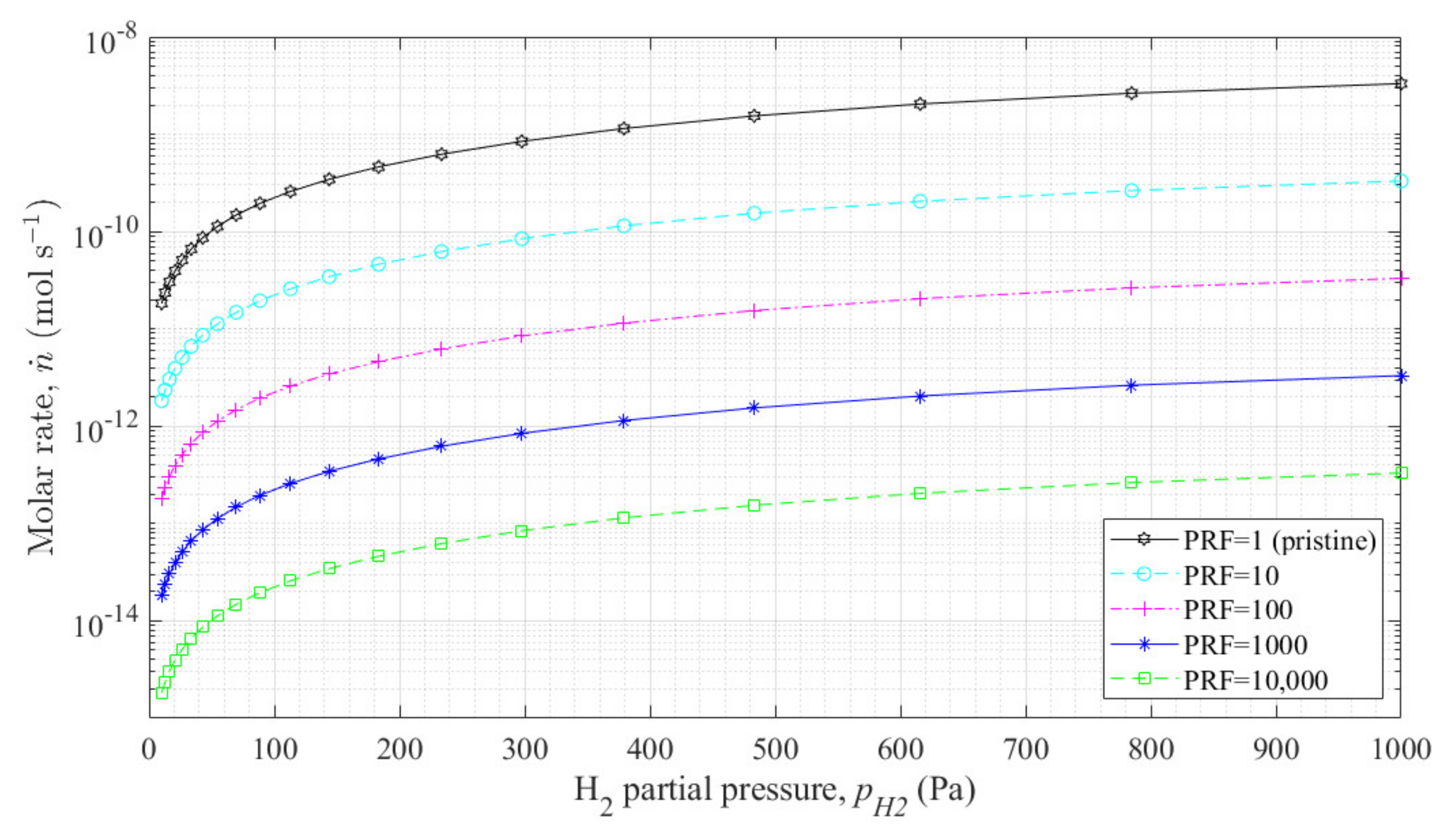
, hence a typical mixed regime characterises the permeation phenomenon. In this case, only numerical solutions for Equation (3) can be obtained. The permeation flux for the gas phase case,
, can be written as:
The calculations were carried out considering different values of the
in the range 1–10,000. The case
represents the case of bare pipe. The results are reported in
Figure 4 in terms of the molar flux
, i.e., the product of permeation flux and external pipe permeation area.
5.2. Liquid Phase Operation
In presence of LiPb, where hydrogen atoms are solubilized in atomic form, a different permeation kinetics establishes. According to [
16], it is possible to describe the permeation regime introducing the so-called partition parameter
which in case of 1D geometry can be expressed as follows:
where
is the partition coefficient, and
is the Sieverts’ constant of the pipe. This dimensionless number depends both on the properties of the pipe and on the properties of the liquid LiPb. Along with the permeation parameter, it is possible to define different limited regimes: the Liquid-Limited Regime (LLR), occurring for
, where the rate limiting phenomenon is the mass transport in the liquid and the Membrane-Limited Regime (MLR), occurring for
, where, at the contrary, the membrane effects are slower with respect to the mass transport in the liquid. For this application,
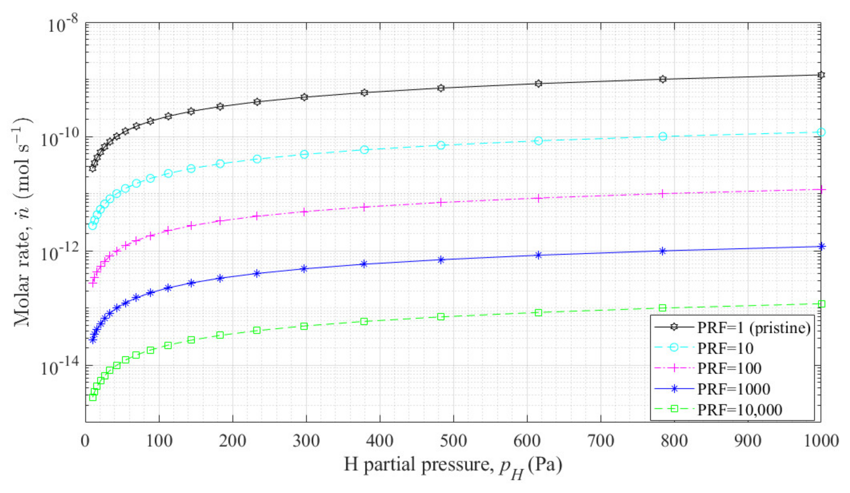
, hence a MLR regime establishes. In this case, the solution is given by the following equation:
As for the gas phase case, the results are reported in terms of the molar flux for different values of the permeation reduction factor,
Figure 5.
6. Conclusions and Future Work
Within this paper, the design of a mock-up for the characterization of antipermeation and corrosion barriers for the WCLL Blanket of ITER and DEMO reactors was presented. It will be used for the characterization of the coating deposition process on EUROFER pipes from the point of view of hydrogen isotopes permeation and it will be installed in TRIEX-II facility at ENEA Brasimone research center, Italy. The mock-up will be internally coated by ALD technique to reduce as much as possible parasitic solubilization of hydrogen or deuterium either solubilized in the liquid lithium-lead or present in gas phase, according to the different steps foreseen in the experimental campaign. The design was carried out in order to guarantee an accurate determination of the PRF associated to the different coatings.
From the results reported in
Section 5, it can be observed that the permeation flux in liquid phase is higher than the one in gas phase only for hydrogen partial pressures lower than 70 Pa; for instance, for p = 10 Pa, the ratio between the two fluxes is 1.5. This is due to the fact that the permeation regime becomes closer to a SLR, in which, at the limit, the permeation flux in liquid phase is twice the one in gas phase. In general, for pressures higher than 70 Pa, the permeation flux in gas phase is the highest (at 1000 Pa is 2.8 times higher than the flux in liquid phase).
Future work will regard two main aspects. Firstly, the finalization of the design and the construction of the test section, along with the installation in TRIEX-II. Secondly, concerning numerical simulations, a 3D numerical transport code which takes into account also the LiPb velocity field in the mock-up will be developed and benchmarked against the obtained experimental results. Additional sensitivity analyses on the surface parameters of EUROFER can be carried out in order to take into account possible oxidation of the steel.
Author Contributions
Conceptualization, M.U., C.A., L.C., F.P. and A.V.; methodology, M.U., C.A. and L.C.; software, L.C.; validation, C.A. and L.C.; formal analysis, M.U., C.A., L.C., F.P. and A.V.; resources, M.U.; data curation, M.U., C.A., L.C., F.P. and A.V.; writing—original draft preparation, M.U., C.A., L.C., F.P. and A.V.; writing—review and editing, M.U., C.A., L.C., F.P., F.D.F. and A.V.; visualization, M.U., C.A., L.C., F.P. and A.V.; supervision, M.U.; project administration, M.U.; funding acquisition, M.U. All authors have read and agreed to the published version of the manuscript.
Funding
This work has been carried out within the framework of the EUROfusion Consortium and has received funding from the Euratom research and training programme 2014–2018 and 2019–2020 under grant agreement No. 633053. The views and opinions expressed herein do not necessarily reflect those of the European Commission.
Institutional Review Board Statement
Not applicable.
Informed Consent Statement
Not applicable.
Data Availability Statement
Not applicable.
Conflicts of Interest
The authors declare no conflict of interest.
References
- Spagnuolo, G.A.; Arredondo, R.; Boccaccini, L.V.; Coleman, M.; Cristescu, I.; Federici, G.; Franza, F.; Garcinuño, B.; Moreno, C.; Rapisarda, D.; et al. Integration issues on tritium management of the European DEMO Breeding Blanket and ancillary systems. Fusion Eng. Des. 2021, 171, 112573. [Google Scholar] [CrossRef]
- Spagnuolo, G.A.; Boccaccini, L.V.; Bongiovì, G.; Cismondi, F.; Maione, I.A. Development of load specifications for the design of the breeding blanket system. Fusion Eng. Des. 2020, 157, 111657. [Google Scholar] [CrossRef] [Green Version]
- Spagnuolo, G.A.; Bongiovì, G.; Franza, F.; Maione, I.A. Systems Engineering approach in support to the breeding blanket design. Fusion Eng. Des. 2019, 146, 31–35. [Google Scholar] [CrossRef] [Green Version]
- Utili, M.; Bassini, S.; Cataldo, S.; Di Fonzo, F.; Kordac, M.; Hernandez, T.; Kunzova, K.; Lorenz, J.; Martelli, D.; Padino, B.; et al. Development of anti-permeation and corrosion barrier coatings for the WCLL breeding blanket of the European DEMO. Fusion Eng. Des. 2021, 170, 112453. [Google Scholar] [CrossRef]
- Iadicicco, D.; Vanazzi, M.; Ferré, F.G.; Paladino, B.; Bassini, S.; Utili, M.; Di Fonzo, F. Multifunctional nanoceramic coatings for future generation nuclear systems. Fusion Eng. Des. 2019, 146, 1628–1632. [Google Scholar] [CrossRef]
- Utili, M.; Bassini, S.; Boccaccini, L.; Bühler, L.; Cismondi, F.; Del Nevo, A.; Eboli, M.; DiFonzo, F.; Hernandez, T.; Wulf, S.; et al. Status of Pb-16Li technologies for European DEMO fusion reactor. Fusion Eng. Des. 2019, 146, 2676–2681. [Google Scholar] [CrossRef]
- Muñoz, P.; Hernández, T.; García-Cortés, I.; Sanchez, F.J.; Maira, A.; Iadicicco, D.; Vanazzi, M.; Utili, M.; Di Fonzo, F.; Moroño, A. Radiation effects on deuterium permeation for PLD alumina coated Eurofer steel measured during 1.8 MeV electron irradiation. Fusion Eng. Des. 2018, 512, 118–125. [Google Scholar] [CrossRef]
- Petráš, R.; Kunzová, K.; Fedoriková, A.; Kekrt, J.; Kordač, M.; Di Fonzo, F.; Paladino, B.; Schroer, C.; Lorenz, J.; Utili, M.; et al. Characterization of aluminum-based coatings after short term exposure during irradiation campaign in the LVR-15 fission reactor. Fusion Eng. Des. 2021, 170, 112521. [Google Scholar]
- Del Nevo, A.; Arena, P.; Caruso, G.; Chiovaro, P.; Di Maio, P.; Eboli, M.; Edemetti, F.; Forgione, N.; Forte, R.; Froio, A.; et al. Recent progress in developing a feasible and integrated conceptual design of the WCLL BB in EUROfusion project. Fusion Eng. Des. 2019, 146, 1805–1809. [Google Scholar] [CrossRef] [Green Version]
- Green, D.W.; Perry, R.H. Equipment for Distillation, Gas Absorption, Phase Dispersion and Phase Separation. In Perry’s Chemical Engineers Handbook, VIII ed.; McGraw-Hill: New York, NY, USA, 2008. [Google Scholar]
- Candido, L.; Nicolotti, I.; Utili, M.; Zucchetti, M. Design Optimization of a Hydrogen Sensor for ITER Pb16Li Blankets. IEEE Trans. Plasma Sci. 2017, 45, 1831–1836. [Google Scholar] [CrossRef]
- Candido, L.; Cantore, M.; Galli, E.; Testoni, R.; Zucchetti, M.; Utili, M.; Ciampichetti, A. Characterization of Pb-15.7Li Hydrogen Isotopes Permeation Sensors and Upgrade of Hyper-Quarch Experimental Device. IEEE Trans. Plasma Sci. 2020, 48, 1505–1511. [Google Scholar] [CrossRef]
- Candido, L.; Alberghi, C.; Antonelli, A.; Bassini, S.; Piccioni, M.; Storai, S.; Testoni, R.; Utili, M.; Zucchetti, M. HyPer-QuarCh II: A Laboratory-scale Device for Hydrogen Isotopes Permeation Experiments. Fusion Eng. Des. 2021, 172, 112920. [Google Scholar] [CrossRef]
- Esteban, G.A.; Perujo, A.; Sedano, L.A.; Mancinelli, B. The surface rate constants of deuterium in the reduced activating martensitic steel OPTIFER-IVb. J. Nucl. Mater. 2000, 282, 89–96. [Google Scholar] [CrossRef]
- Ali-Khan, I.; Dietz, K.J.; Waelbroeck, F.G.; Wienhold, P. The rate of hydrogen release out of clean metallic surfaces. J. Nucl. Mater. 1978, 76–77, 337–343. [Google Scholar] [CrossRef]
- Humrickhouse, P.W.; Merrill, B.J. Vacuum permeator analysis for extraction of tritium from DCLL blankets. Fusion. Sci. Technol. 2015, 68, 295–302. [Google Scholar] [CrossRef]
| Publisher’s Note: MDPI stays neutral with regard to jurisdictional claims in published maps and institutional affiliations. |
© 2022 by the authors. Licensee MDPI, Basel, Switzerland. This article is an open access article distributed under the terms and conditions of the Creative Commons Attribution (CC BY) license (https://creativecommons.org/licenses/by/4.0/).


 ,
, 


