1. Introduction
In the event of an acute ischemic stroke, the blood supply is occluded in the cerebral blood vessels, thus causing cerebral infarction which may lead to severe neurological impairment and even death [
1]. Studies have shown that thrombolytic treatment is feasible and effective in treating patients with acute ischemic stroke using tissue plasminogen activator (tPA), which is the only thrombolytic drug approved by the Food and Drug Administration (FDA) and, correspondingly, therapeutic goods administration (TGA) [
2]. However, the administration of tPA requires a prior brain scan via a CT scanner to determine the suitability of such medication, and its usage is generally constrained to a time window of up to 4.5 h (or up to 9 h with CT-perfusion selection to detect potentially reversible ischemia) after the onset of stroke, where its effectiveness decreases as time progresses [
3]. Due to its highly time-sensitive nature, earlier stroke treatments should be enforced to improve the likely patient outcome, where ideally treatment should be administered within the first hour after the onset of stroke symptoms—the ‘golden hour’ for the best recovery result [
4,
5]. In order to treat such disorders in large countries where the community is sparsely located away from hospital services, alternative avenues are being assessed. One such avenue is a mobile stroke unit.
2. Mobile Stroke Unit
To approach the time-sensitive stroke treatment procedure, the concept of MSU was first realized in 2003, with the idea of bringing the ‘hospital’ to the patient [
6], and was integrated in clinical reality in Homburg, Germany in 2008 [
7]. However, in 2016, the PRE-hospital Stroke Treatment Organization (PRESTO) was formed, which consisted of an international consortium of medical practitioners from Europe, the U.S.A., Canada, and Australia to support research and advocacy for pre-hospital stroke treatment in MSUs. The pre-hospital treatment and diagnosis provided by the MSU must adhere to current stroke guidelines and emergency medical services (EMS) legislations [
8]. The MSU essentially works by delivering prehospital diagnosis and treatment to stroke patients for immediate medical evaluation and triage, and the administration of appropriate treatment (e.g., tPA) while on site. The BEST-MSU randomized trial recently provided proof of concept for significant disability reduction for tPA-eligible patients treated using an MSU care delivery paradigm [
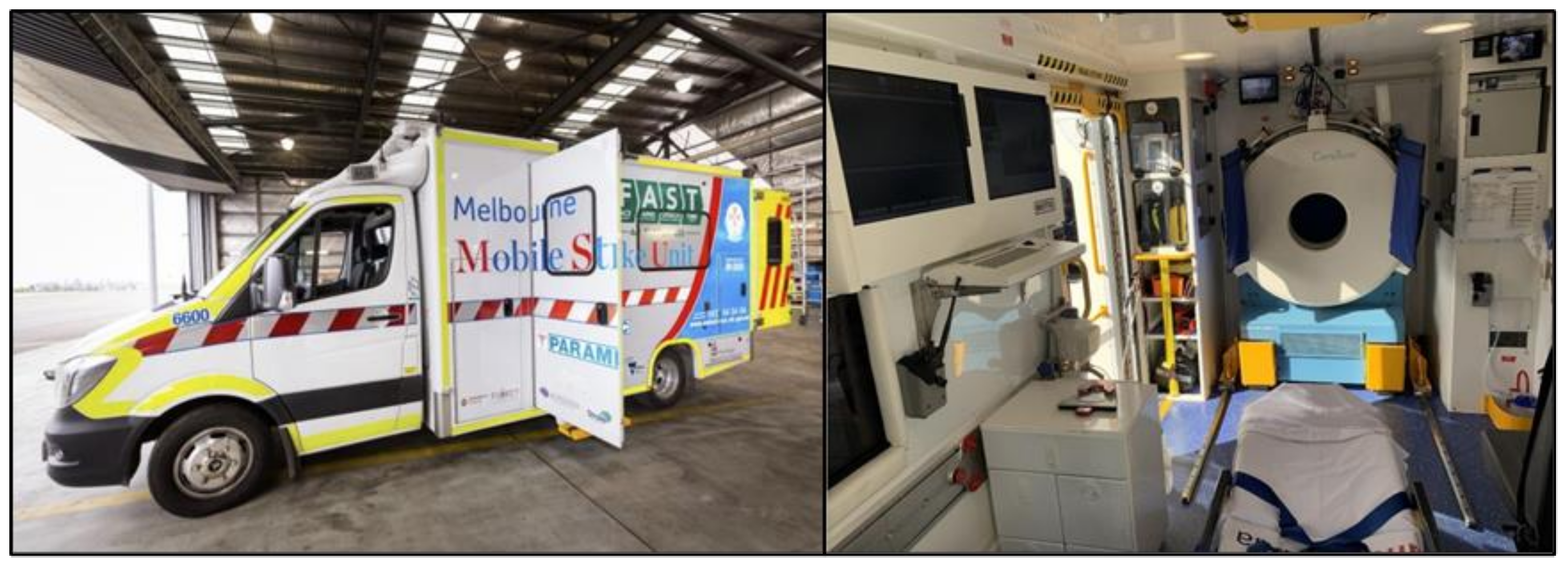
9]. A customized ‘stroke ambulance’ used for MSU (
Figure 1), which is integrated with multiple working systems, typically includes: (i) a modified mobile CT scanner and an operation console for screening procedures, (ii) a telemedicine system for transferring digital images and clinical data of the patient to the hospital’s database to be evaluated by a vascular neurologist and a neuroradiologist, (iii) a point-of-care laboratory for determining the suitability of administering tPA, and (iv) a lightweight stretcher for the patient to lie on and align their head to the CT scanner. There are usually three to four seats installed for the on-board medical staff, which typically consists of but is not limited to a paramedic, a CT technologist, and a nurse with specialized stroke training [
10,
11,
12,
13].
However, most customized MSUs are commonly set up in the heart of metropolitan areas where the majority of patients are situated. As such, rural and remote communities do not have access to the same diagnostic tools [
15]. A study shows promising results in expanding the catchment area of MSU by implementing a rendezvous system, where an MSU dispatched from the metropolitan area will coordinate and meet with an EMS outside of the MSU’s catchment area, and the EMS unit will evaluate the patient in parallel with the MSU team before sending to the nearest stroke center [
16]. However, such a system requires extensive planning and coordination between the MSU and all the EMS units involved within the catchment area and would require a robust and unified communication system to ensure an efficient collaboration.
3. Helicopter Emergency Medical Services and Air-MSU
3.1. HEMS Applications and Potential
Helicopter emergency medical services (HEMS) were traditionally used for trauma transfers and have increased popularity for use in providing triage and transportation for stroke patients to the nearest medical facilities or interfacility transportations since the approval of perfusion treatment for stroke by the FDA [
17,
18].
HEMS have been proven to improve the accessibility of stroke care for a wide range of communities from highly rural to urban areas by providing timely transportations within the treatment window. A study aggregated the data of HEMS dispatch between 2004 to 2011 in the United States of America and reported that the majority of the transported patients arrived at a primary stroke center in less than 2 h after dispatch [
19]. However, a recent study on aeromedical retrievals for stroke patients residing in rural Australia revealed that the transfer times are still largely outside of the recommended time window for reperfusion treatments; this is due to the scarcity of relevant stroke centers in rural and remote areas, where the establishment of additional stroke centers remains unfeasible due to the sparsely distributed population across vast areas [
20].
Thus, the invention of MSU has opened opportunities to evolve the technology into an air version of the MSU (hereafter named the Air-MSU). Air-MSU can potentially deliver diagnosis and administer tPA where applicable to stabilize the stroke patient’s condition on site before transporting to a specialized stroke center for more sophisticated medical evaluation and treatment. It is worth noting that the CT scanning procedure for diagnosing is only carried out once the helicopter has landed onto a suitable terrain with a minimal slope.
3.2. Air-MSU Concept
To date, most MSUs have been developed for urban and metropolitan areas. Stroke physicians have seen the limitations and potential applications for patients living in rural and remote areas. The concept of Air-MSU for delivering acute stoke treatment to rural patients has been proposed [
21]. Although the concepts of both road and Air-MSU are fundamentally the same, they have different technical challenges and limitations [
22]. For example, to align with the rotorcraft flight manual (RFM) as approved by the European Union Aviation Safety Agency (EASA) under the Airworthiness Directive (AD), the optimal weight limit and balance must be achieved within a defined center-of-gravity range, as they affect the flight performance of the corresponding aircraft [
23], and the materials used for the interior of an aircraft must comply with the applicable flammability requirements for that aircraft type [
24]. In order to maintain the performance of the medical devices (and in this specific case, the CT scanner) installed in an aircraft, they must show resilience to mechanical vibrations, sudden pressure changes, and any electromagnetic interferences. Depending on the catchment of rural and remote areas, the Air-MSU needs to demonstrate resilience to extreme temperature changes as well as dust that might affect the performance of the CT scanner. Current commercially available CT scanners are traditionally designed for hospitals; thus, to be operated in an aircraft or rotorcraft that may be subjected to vibration, dust, and temperature variations, modification is required. Therefore, fixations between the CT scanner and the interior of the aircraft must be designed with a much higher safety factor than its road MSU counterpart to account for the events of an emergency landing [
21]; this will undoubtedly influence the structural design and material selection process of the CT scanner. The current literature and application regarding Air-MSU is still very limited, where the Norwegian Air Ambulance Foundation has announced their collaboration with Semcon to work on developing a lightweight and small pre-hospital CT scanner which can be fitted into a helicopter, and similar work was proposed from the collaboration between Micro-X and Royal Flying Doctor Service.
3.3. Aircraft Selection
When selecting an appropriate aircraft for Air-MSU, the choices are between a fixed wing and a rotor wing. The former is capable of covering a larger distance with greater speed, although it requires a runway; the latter generally has a smaller coverage distance and a lower speed but does not require a runway, allowing for more flexible landing options. Walter et al. [
22] presented a table of existing helicopters for technical comparison, where it can be seen that the cabin size for helicopters used for HEMS tend to be smaller than those for search-and-rescue missions and military operations. Aeromedical rotorcrafts come in different sizes, each designed for different purposes and operating in different locations. When designing for Air-MSU, selecting a larger rotorcraft not only allows for a higher payload carriage but also a larger cabin room, easing the process of integrating a CT scanner and any additional equipment required into the nominated aircraft. Furthermore, having a larger cabin room also means more working space for both the medical staff during operation and personnel performing maintenance work for the CT scanner.
In collaboration with the Australian Stroke Alliance, Agusta Westland 189 (
Figure 2) was selected as the rotorcraft model for retrofitting a proposed CT scanner as it has a relatively large cabin size.
4. Mobile Head CT Scanner and Rotorcraft Retrofitting
4.1. Types of Portable Head CT Scanners
There are several types of commercially available CT scanners depending on the diagnostic purposes, body organs to be examined, and sensitivity and specificity. As the MSU and Air-MSU are designed to diagnose and distinguish between ischemic stroke (stroke where blood flow to the brain is blocked by a clot) and hemorrhagic stroke (stroke where a blood vessel bursts) from a suspected stroke patient, a CT scanner that can perform brain scans via non-contrast CT is sufficient. Therefore, full-body scanners are neglected since they generally have a larger build than head CT scanners and are unnecessary for head scans. Portable head CT scanners are designed to deliver head CT scans to stroke patients by the bedside; thus, they are designed to be as lightweight and compact as possible to maximize portability. While the image quality is lower than that of a conventional hospital floor-fixed CT scanners, portable CT scanners are shown to have sufficient diagnostic quality [
26].
Table 1 shows four commercial mobile head CT scanners with their respective technical specifications (
Table 1).
Although the technology of each machine varies between one and another, they are all capable of performing head CT scans with sufficient diagnostic quality; hence, the imaging-quality aspect will not be compared and analyzed between each model. All four mobile head CT scanner models share the similarity of having a built-in trolley system which allows the scanner to be easily maneuvered. They also have a computer unit built-in which is used for controlling various functions of the mobile head CT scanners. As each mobile head CT scanner has a unique mechanical and structural design, the retrofitting process will vary between each model. Therefore, it is important to generalize and identify the key design constraints and criteria. An example of the CereTom and xCAT models are shown in
Figure 3.
4.2. Design Considerations for Retrofitting Head CT Scanners into Rotorcraft
When retrofitting a mobile head CT scanner into a rotorcraft, several technical properties must be taken into account before modifying for retrofitting, which include:
Major components of the mobile head CT scanner;
Weight and size of the mobile head CT scanner;
Actuation mechanism of the mobile head CT scanner.
4.2.1. Major Components of the Mobile Head CT Scanner
The total weight of a CT scanner is from the accumulation of different components assembled within the structure. It is therefore important to identify the components and determine if they can be, replaced, removed, or modified to reduce the size and/or weight where possible. Unlike the conventional hospital floor-fixed CT scanners, the portable CT scanners are the smaller counterparts, and they are designed to allow hospital staff to transport the scanner to the patient. Therefore, they have lesser components and are drastically lighter in exchange for lower imaging quality and are more suitable for fitting into an aircraft. The typical parts that can be found in a portable head CT scanner are labeled in
Figure 4.
Table 2 describes the role of each component, determining whether to keep, remove, or modify, and justification for each decision. When modifying the CT scanner to be retrofitted, it is important to first identify the major functioning components and their roles, and, correspondingly, determine whether modification will interfere with the primary function of the CT scanner. In order to simplify the design process, certain components will be kept at default to avoid disrupting the primary function of the CT scanner to avoid complicating the modification process.
4.2.2. Weight and Size of the Mobile Head CT Scanner
With the major components identified and determined for modification, removal, or keeping (
Table 2), the CT scanner can then proceed to be modified accordingly. As CereTom is 13 cm taller than the cabin height of an AW189, lower compartment, fender, and caster wheels were proposed to be removed from the main structure of the CT scanner. Therefore, a new support structure is needed to attach the gantry of the CT scanner to the helicopter floor.
The weight and geometry of the CT scanner are the two most important factors to consider when designing a suitable support structure to attach the CT scanner onto the helicopter floor. Firstly, the support structure should demonstrate sufficient strength to resist both the static weight of the CT scanner gantry and the components concealed within and the vibrations induced from both the rotation of the CT scanner during operation and the helicopter floorboard during flight and landing. Therefore, it is ideal to select the lightest mobile head CT scanner model where possible as it simplifies the design process by lowering the amount of weight reduction required, and the proposed support structure will have a lighter weight and smaller size as it has a lower load-bearing requirement. For the geometry of the CT scanner gantry, it is ideal to design a support structure that can attach to it while keeping the overall dimensions of the CT scanner as small as possible to allow for more working space for the onboard staff within the small enclosure of the aircraft interior.
4.2.3. Actuation Mechanism of the Mobile Head CT Scanner
Different CT scanners utilize different mechanical actuations for translation during the scanning process; therefore, it is important to first identify the mechanism as it directly influences the complexity and design of the support structure. For example, the translation of the entire body of CereTom is accumulator-driven. For SOMATOM Onsite, the CT scanner consists of a telescopic gantry, where the inner section elongates while the rest of the structure remains stationary during the scanning process [
28]. For xCAT, there is no translation involved since it uses cone beam technology which performs a volumetric scan through a single gantry rotation [
30]. To ensure the CT scanner’s travel is unidirectional and precise, multiple MSU programs were seen installing linear guides to assist the CT scanner during translation [
14,
31]. Therefore, for CT scanners where the entire structure is designed to travel during scanning, additional mechanical guides must be designed in addition to the support structure, while for CT scanners where only part of the gantry translates, a simple fixed support structure is adequate.
4.2.4. CereTom and AgustaWestland AW189
Currently, CereTom by Neurologica is one of the most popular commercial off-the-shelf portable CT scanners and is reported to be used in multiple road MSU programs across the world [
11,
15,
31,
32]. This has been attributed to its small and lightweight nature. However, the CereTom still poses a relatively heavy (438 kg) single piece of equipment for an air ambulance, and its weight needs to be further reduced for improved aircraft weight distribution and flight performance. Bil et al. illustrated the cabin layout of a fixed-wing (Pilatus PC-24) and rotor-wing (NH90) aircraft attached with a CT scanner; however, the illustrations served as a preliminary concept and lacked details on how the CT scanner is attached to the aircraft’s interior [
22].
In this case study, CereTom by NeuroLogica along with the search and rescue helicopter AgustaWestland 189 are selected according to the project requirements provided by our collaborating partners and manufacturers for the retrofitting and design process. In collaboration with Australian Stroke Alliance and Melbourne Brain Centre, the current CereTom model used in Australia’s first-ever road MSU will be acquired and will form the basis to initiate the design process, subsequently extending the applicable principles onto the Air-MSU concept. The aim of this research is to explore a methodology in designing a lightweight CT scanner structure that can be retrofitted into the proposed search-and-rescue helicopter model—the AW189 model.
5. So, How Can We Take It to the Skies?
A central challenge in the long-term expansion of MSU to the skies is a systematic design and development approach for a lightweight CT scanner and the integration into a selected helicopter.
5.1. A Model-Based System Engineering Design (MBSE) Approach
The design and development process for medical devices has traditionally followed a linear waterfall approach (
Figure 5) [
32]. It is a basic logical sequential design process, usually starting with capturing the requirements (users, products, regulatory, etc.), and each phase must be reviewed, verified, and completed before the next phase can begin. The waterfall linear approach has limitations such as the fact that each phase of development proceeds in a strict order, which makes it hard to accommodate change requirements throughout the product lifecycle management (PLM) phases, and it is not suitable for complex designs.
In recent years, collaborative and concurrent design together with realistic engineering and manufacturability considerations have attracted the interest of many researchers. To ensure that the medical devices can be tested faster and more reliably, and to accelerate their time from concept to market, efforts must be directed towards fulfilling regulatory requirements and pushing innovation in a sustainable way.
Furthermore, the design, development, and dissemination of medical devices are regulated by regulatory bodies around the world such as the FDA in the USA, the Therapeutic Goods Administration (TGA) in Australia, and the European Medicines Agency in the European Union to ensure the safety and efficacy of the products. Through a complex system of legislation, the time from concept to market for medical devices, which includes the review and approval processes that meet requirements for conformity, can be lengthy and costly [
33].
Hence, to realize such a vision to transform ideas from industry–academia collaboration, we proposed a new approach that complements the ‘V’ model (
Figure 6). It is a direct approach of integrating collaborative and concurrent product design on a single virtual design platform with model-based system engineering (MBSE).
In reducing the weight and size of a complex CT scanner to retrofit into a search and rescue helicopter, an appropriate framework is required to assist in designing and testing medical devices virtually before introducing them into the physical world. As the project involved multiple stakeholders, the effectiveness and efficiency of the proposed design required input and effort from people of multiple disciplines including engineering, medicine, legal, technical, etc.
Through the proposed MBSE diamond approach, we would develop a digital twin of CT scanner and aircraft. Digital twin is commonly known as a digital or virtual representation of a physical entity, and a bidirectional connection of data between them for the purpose of improving the performance of the physical part using computational modelling and simulations [
34]. The key feature of the MBSE diamond approach is the creation of digital models to design and optimize systems before the first physical item is built. It also allowed continuous improvement and enabled scope flexibility, team input, and the delivery of a quality product that emphasized verification and validation with the use of test cases to ensure adherence to which the product should be built as-designed data and vice versa [
33].
The design process for modifying and retrofitting a CT scanner can be classified into three steps: (1) default structure reduction, (2) support structure design, and (3) integration onto mobile interior (Agusta Westland AW189). CATIA (Dassault Systèmes, Vélizy-Villacoublay, France), three-dimensional computer-aided design software, was used to model both the CT scanner model and the cabin interior of AW189.
5.2. Reducing a Default CereTom Structure and Geometry
The first step to decrease the weight of the CT scanner is to look at structural modification. Referring to the common CT scanner found in MSUs, the CereTom, it is possible to remove the entire lower compartment, fender, trackwheels, and caster wheels to reduce a CereTom to just the gantry. As such, structural modification can occur to decrease the default geometry of a CereTom without impeding its main functions. Furthermore, the outer frame was proposed to be removed, where the LCD control panel and lead curtains which were previously attached were modified and/or repositioned away from the CT scanner structure. Furthermore, battery units and processors which are concealed in the lower compartment were repositioned away from the main structure of the CT scanner so that the entire lower compartment is removed. Along with the removal of the fender and caster wheels, the default height and width of CereTom were effectively reduced from 153 cm and 134 cm down to just the diameter of the gantry at approximately 49 cm, and the depth of the gantry at approximately 44 cm (
Figure 7).
5.3. Designing a Support Structure for Reduced CereTom Gantry
In order to house the modified gantry of CereTom within the AW189, the default caterpillar tracks along with an individual stepper motor attached on each side may be replaced with a ball screw mechanism to reduce the bulkiness of the structure while maintaining a high-precision translation, where a support structure was implemented with its geometrical features designed according to a ball-screw-driven linear guide system. To size the support structure for the modified gantry of CereTom, the maximum allowable design space was confined to the default width and depth of CereTom, which are 134 cm and 73 cm, respectively, and the cabin height of the AW189, which is 140 cm. A conceptual CAD model of the support structure has been suggested in
Figure 8 for the modified gantry, where it has adopted a shell-like geometry to minimize material use and weight.
5.4. Designing a Base Plate for Proposed Support Structure and Full Assembly
A base plate is designed for two linear guides to be attached, where the plate will be bolted to the helicopter floor accordingly for different helicopter models. A support block will be bolted onto the base plate for mounting the ball screw shaft, and two locking brackets are installed to the sides of the base plate for locking the entire CT scanner in a stowed position (
Figure 9).
The ball nut is fixed to the support block, then the ball screw shaft is inserted into the support structure, through the ball nut and support block. A motor is then attached to a gearbox, where the gearbox is mounted onto the support structure and attached to the ball screw shaft. The other end of the ball screw shaft will be supported with a ball bearing which is inserted into a hole located inside the support structure. A gearbox with a worm gear and worm wheel is selected to increase the output torque and redirect the transmitted torque perpendicularly; this is to reduce the overall length of the entire CT scanner model. Finally, the modified gantry is mounted onto the support structure via a dovetail joint, where the support structure is secured onto the sliders, which are mounted onto the linear guides (
Figure 10).
By comparing with the original CereTom model (
Figure 4) and the newly modified CT scanner model (
Figure 11), it can be seen that the lower compartment was removed in the CAD model, where the default caster wheel and caterpillar track mechanism were removed altogether. The battery units as well as the computers which were concealed within the lower compartment are repositioned away from the main structure. Furthermore, the circular outer frame along with the LCD control unit were removed and repositioned, respectively, while the lead curtains were modified to attach directly to the gantry.
As the interior of air MSU will be exposed to dusty and harsh environments of regional Australia during operation, dust build-up from use over time may cause the default caterpillar tracks to slip during actuation and impede the performance of the CT scanner. Therefore, it was replaced with a highly dust-resistant ball screw design to tackle on this issue. Additionally, the support structure was designed to conceal the entire ball screw mechanism for additional dust protection. By comparing with the original CereTom model with the newly modified CT scanner model, the total height, width, and depth have been decreased by approximately 33 cm, 34 cm, and 29.4 cm, respectively. The current design allows the CT scanner to travel for up to 40 cm in the longitudinal direction (
Figure 12).
5.5. How Do We Integrate into a AW189 Helicopter?
In order to integrate the modified CT scanner structure into the AW189, it is important to first identify the overall dimensions of the interior of AW189, which can be seen in
Figure 10. The entire CT scanner geometry was designed such that it does not impede the cabin entrance and exit any point.
The shape of the AW189 interior consists of two sections—the main cabin and rear storage—and a proposed layout of the racks and CT scanner is as illustrated in
Figure 13. The battery units and computers are repositioned from the default CereTom structure to the vacant spaces on the adjacent racks, where the LCD control panel is repositioned to the racks as well since the device is connected wirelessly. The default battery used in CereTom operates between 90 to 264 volts in an alternating current and at 1300 watts during the peak, where typical operations range between 110 to 120 volts. It can operate for up to 2 h when fully charged for typical operations [
35]. For the application of Air-MSU, the battery’s reserve power serves as a backup and is strictly for use during emergency events only and can be charged via the helicopter’s auxiliary power unit (APU) during flight. Therefore, during normal operations, the CT scanner draws power directly from the APU.
With the current design and layout, there is a head space of up to 23 cm between the CT scanner and the interior roof of AW189, providing additional room for further modifications where required, and the CT scanner is clear from the doorway of AW189. Furthermore, the central axis of the CT scanner bore is spaced at 67.5 cm above the rotorcraft floor, where this dimension will be crucial in selecting a stretcher that provides sufficient elevation. The stretcher will be attached to the helicopter floorboard via a fastening system, which also helps guide the movement of the stretcher and docking in a fixed position, similar to the Royal Melbourne Hospital road MSU setting.
5.6. During Flight and Maintenance
During flight, a helicopter may undergo different flight settings such as yawing and rolling and experience different flight conditions such as turbulence, which may tilt and vibrate the helicopter. Hence, it is crucial to restraint any moving objects within the helicopter to avoid inflicting any damage to the equipment or injuries to the medical staff onboard. One method of restraining the CT scanner is proposed, where two locking brackets are installed on both sides of the base plate, which aligns with the flanges on the sides of the support structure when the CT scanner is fully extended; a heavy-duty spring-loaded locking pin is then used on each bracket to lock the CT scanner in a stowed position (
Figure 14). The geometry of the locking bracket was designed resembling a hook to prevent the CT scanner from displacing upwards, where the pins are there to prevent the CT scanner from sliding back and forth along the linear guides. Locking mechanisms are especially important when restraining a ball-screw-driven linear guide system installed within a mobile environment, as it helps relieve the stresses concentrated towards the sliders and ball bearings situated within the ball nut during stowing.
During maintenance, the CT scanner can be controlled to displace forward and fully retract; this creates a space of up to 35 cm between the CT scanner and the adjacent racks for the technician to access the back of the CT scanner and provides a working space of up to 72 cm between the CT scanner and the wall of AW189 (
Figure 15).
6. Challenges and Perspectives
Even though numerous studies in the MSU have shown promising results in terms of bringing prehospital diagnosis and treatment to stroke patients within the golden hour, a number of challenges remain that need to be addressed in order to facilitate the development of the MSU, in particular within the Air-MSU, where the need is greatest for regional and remote locations in Australia.
The major challenge persists in finding an optimal balance between minimizing the weight while maximizing the structural integrity of the support structure. The support structure must be designed to withstand the static weight of the CT scanner, the rotational force induced by the rotating drum when it is spinning during scanning, and the vibrations induced by the helicopter floor during flight. One such property that is important to ensure is that there are no severe stress concentrations located on the profile of the support structure and that it demonstrates sufficient structural strength. Hence, topology optimization, which is a mathematical method that optimizes material distribution within a given design space, would allow us to optimize the support structure by maximizing its stiffness-to-weight ratio and removing underutilized material where possible to reduce the weight of the structure.
In addressing the impact of vibration, an initial component of a successful impact assessment procedure is to start by reviewing the 3D design early in the design process, then conducting the virtual realization, which consists of computer modelling and simulation to identify the sources of vibration, which may be of concern for the integration of the proposed CT scanner into an aircraft. The level of vibration in terms of the fundamental resonant frequency, damping, amplitude, and mode shape will be determined with the spaces and layouts of a given aircraft design. The simulated data will then be shared and reviewed with the equipment suppliers or manufacturers to check the specification criteria and vibration responses for their specific lines of CT scanners. This will assist the design team to devise some typical base strategies that can be implemented or considered in working to mitigate the vibration impact on the proposed CT scanner. A mitigation solution may involve reinforcing the aircraft floor and incorporating vibration suppression and stabilization for the CT scanner system.
Medical device manufacturers face countless challenges that require them to be flexible to make a decision on ‘go’ or ‘no-go’ and modify the project plan to meet the required quality, safety, and performance standards while ensuring the traceability of information and intellectual property throughout the development process. To address such challenges, we need to look beyond the constraints of the existing norms and practices, as well as the biomedical domain of expertise. Thus, the proposed ‘V’ model of the system engineering approach, which allows for virtual analysis, testing, and validation, and in parallel connecting to the physical assets, is considered as the most promising choice.
Any modification to the existing CT scanner may lead to manufacturers and users to question the overall safety while maintaining good-quality images of the newly modified lightweight CT scanner. This question could be addressed systematically by following standardized protocols to equip the modified lightweight CT scanner with safeguards and shielding. This certainly requires the collaboration and development in partnership with the medical device manufacturers, where validation and verification will be carried out in collaboration with aircraft solutions companies and CT scanner manufacturers in accordance with the specifications and quality attributes listed in TGA and CASA guidelines.
7. Conclusions
It is important to ensure that any CT scanner proposed for Air-MSU applications can function accurately and freely. Considerable work has been undertaken to develop road-based MSUs around the world; however, limitations in Air-MSU remain. While the majority of current research focuses on designing a brand-new concept CT scanner model suitable for fitting into a helicopter, this research focuses on a more feasible albeit less ambitious approach at bringing Air-MSU closer into realization sooner through the retrofitting of an existing portable head CT scanner into an SAR helicopter. This will eliminate the pending process for approval from regulatory bodies for a brand-new CT scanner model to be commercialized, that is, assuming the new model has been successfully tested and is fully operational. Here, we have proposed a new method to take the most common mobile CT scanner, the CereTom, and modify it for use within an AW189 footprint. Further efforts will be directed towards assessing the structural integrity of the proposed CT scanner structure and reducing its weight.
Author Contributions
Conceptualization, J.S.K., T.Y.P., K.F., F.L., F.G., M.P., H.D.A., B.C., D.E, and C.B. (Cees Bil); methodology, J.S.K., K.F., and T.Y.P.; writing—original draft preparation, J.S.K., T.Y.P., F.L., M.P., H.Z., and K.F.; writing—review and editing T.Y.P., K.F., C.B. (Cees Bil), D.E., F.L., A.H.B., A.D.S., A.B., F.G., C.B. (Christopher Bladin), H.Z., S.C., C.L., and G.A.D.; project administration, C.B. (Cees Bil),D.E., H.D.A., B.C., S.M.D., K.F., and G.A.D.; funding acquisition, M.P., D.E., H.D.A., C.B. (Cees Bil), B.C., S.M.D., and G.A.D. All authors have read and agreed to the published version of the manuscript.
Funding
This research was funded by the Australian Government Department of Health Medical Research Future Fund, Frontier Health and Medical Research Grant.
Institutional Review Board Statement
Not applicable.
Informed Consent Statement
Not applicable.
Acknowledgments
We acknowledge the resources and support of the Australian Stroke Alliance and the Melbourne Brain Center.
Conflicts of Interest
The authors declare no conflict of interest.
References
- Lewandowski, C.A.; Frankel, M.; Tomsick, T.A.; Broderick, J.; Frey, J.; Clark, W.; Starkman, S.; Grotta, J.; Spilker, J.; Khoury, J.; et al. Combined Intravenous and Intra-Arterial r-TPA Versus Intra-Arterial Therapy of Acute Ischemic Stroke. Stroke 1999, 30, 2598–2605. [Google Scholar] [CrossRef] [PubMed]
- Claiborne Johnston, S.; Fung, L.H.; Gillum, L.A.; Smith, W.S.; Brass, L.M.; Lichtman, J.H.; Brown, A.N. Utilization of Intravenous Tissue-Type Plasminogen Activator for Ischemic Stroke at Academic Medical Centers. Stroke 2001, 32, 1061–1068. [Google Scholar] [CrossRef] [PubMed] [Green Version]
- Ma, H.; Campbell, B.C.V.; Parsons, M.W.; Churilov, L.; Levi, C.R.; Hsu, C.; Kleinig, T.J.; Wijeratne, T.; Curtze, S.; Dewey, H.M.; et al. Thrombolysis Guided by Perfusion Imaging up to 9 Hours after Onset of Stroke. N. Engl. J. Med. 2019, 380, 1795–1803. [Google Scholar] [CrossRef] [PubMed]
- Strbian, D.; Soinne, L.; Sairanen, T.; Happola, O.; Lindsberg, P.J.; Tatlisumak, T.; Kaste, M.; Helsinki Stroke Thrombolysis Registry, G. Ultraearly thrombolysis in acute ischemic stroke is associated with better outcome and lower mortality. Stroke 2010, 41, 712–716. [Google Scholar] [CrossRef] [PubMed] [Green Version]
- Emberson, J.; Lees, K.R.; Lyden, P.; Blackwell, L.; Albers, G.; Bluhmki, E.; Brott, T.; Cohen, G.; Davis, S.; Donnan, G.; et al. Effect of treatment delay, age, and stroke severity on the effects of intravenous thrombolysis with alteplase for acute ischaemic stroke: A meta-analysis of individual patient data from randomised trials. Lancet 2014, 384, 1929–1935. [Google Scholar] [CrossRef] [Green Version]
- Fassbender, K.; Walter, S.; Liu, Y.; Muehlhauser, F.; Ragoschke, A.; Kuehl, S.; Mielke, O. “Mobile Stroke Unit” for Hyperacute Stroke Treatment. Stroke 2003, 34, e44. [Google Scholar] [CrossRef]
- Walter, S.; Kostpopoulos, P.; Haass, A.; Helwig, S.; Keller, I.; Licina, T.; Schlechtriemen, T.; Roth, C.; Papanagiotou, P.; Zimmer, A.; et al. Bringing the hospital to the patient: First treatment of stroke patients at the emergency site. PLoS ONE 2010, 5, e13758. [Google Scholar] [CrossRef]
- Audebert, H.; Fassbender, K.; Hussain, M.S.; Ebinger, M.; Turc, G.; Uchino, K.; Davis, S.; Alexandrov, A.; Grotta, J.; Group, P. The PRE-hospital Stroke Treatment Organization. Int. J. Stroke 2017, 12, 932–940. [Google Scholar] [CrossRef] [Green Version]
- Grotta, J.C.; Yamal, J.-M.; Parker, S.A.; Rajan, S.S.; Gonzales, N.R.; Jones, W.J.; Alexandrov, A.W.; Navi, B.B.; Nour, M.; Spokoyny, I.; et al. Prospective, Multicenter, Controlled Trial of Mobile Stroke Units. N. Engl. J. Med. 2021, 385, 971–981. [Google Scholar] [CrossRef]
- Shuaib, A.; Jeerakathil, T.; Alberta Mobile Stroke Unit, I. The mobile stroke unit and management of acute stroke in rural settings. CMAJ 2018, 190, E855–E858. [Google Scholar] [CrossRef] [Green Version]
- Zhao, H.; Coote, S.; Easton, D.; Langenberg, F.; Stephenson, M.; Smith, K.; Bernard, S.; Cadilhac, D.A.; Kim, J.; Bladin, C.F.; et al. Melbourne Mobile Stroke Unit and Reperfusion Therapy: Greater Clinical Impact of Thrombectomy Than Thrombolysis. Stroke 2020, 51, 922–930. [Google Scholar] [CrossRef] [PubMed]
- Ehntholt, M.S.; Parasram, M.; Mir, S.A.; Lerario, M.P. Mobile Stroke Units: Bringing Treatment to the Patient. Curr. Treat. Options Neurol. 2020, 22, 5. [Google Scholar] [CrossRef]
- Fassbender, K.P.; Grotta, J.C.P.; Walter, S.M.D.; Grunwald, I.Q.P.; Ragoschke-Schumm, A.M.D.; Saver, J.L.P. Mobile stroke units for prehospital thrombolysis, triage, and beyond: Benefits and challenges. Lancet Neurol. 2017, 16, 227–237. [Google Scholar] [CrossRef]
- Zhao, H.; Campbell, B.C.V.; Foster, S.; Stephenson, M.; Coote, S.; Langenberg, F.; Easton, D.; Donnan, G.A.; Davis, S.M. Advances in pre-hospital care—Operational experiences from the Melbourne mobile stroke unit. Vessel Plus 2021, 5, 2021. [Google Scholar] [CrossRef]
- Cadilhac, D.A.; Kilkenny, M.F.; Longworth, M.; Pollack, M.R.; Levi, C.R.; Metropolitan Clinical, T.; Stroke Services New South Wales Coordinating, C. Metropolitan-rural divide for stroke outcomes: Do stroke units make a difference? Intern. Med. J. 2011, 41, 321–326. [Google Scholar] [CrossRef]
- Parker, S.A.; Kus, T.; Bowry, R.; Gutierrez, N.; Cai, C.; Yamal, J.M.; Rajan, S.; Wang, M.; Jacob, A.P.; Souders, C.; et al. Enhanced dispatch and rendezvous doubles the catchment area and number of patients treated on a mobile stroke unit. J. Stroke Cerebrovasc. Dis. 2020, 29, 104894. [Google Scholar] [CrossRef] [PubMed]
- Tonsager, K.; Rehn, M.; Ringdal, K.G.; Lossius, H.M.; Virkkunen, I.; Osteras, O.; Roislien, J.; Kruger, A.J. Collecting core data in physician-staffed pre-hospital helicopter emergency medical services using a consensus-based template: International multicentre feasibility study in Finland and Norway. BMC Health Serv. Res. 2019, 19, 151. [Google Scholar] [CrossRef] [Green Version]
- Thomas, S.H.; Kociszewski, C.; Schwamm, L.H.; Wedel, S.K. The evolving role of helicopter emergency medical services in the transfer of stroke patients to specialized centers. Prehosp. Emerg. Care 2002, 6, 210–214. [Google Scholar] [CrossRef] [PubMed]
- Hutton, C.F.; Fleming, J.; Youngquist, S.; Hutton, K.C.; Heiser, D.M.; Barton, E.D. Stroke and Helicopter Emergency Medical Service Transports: An Analysis of 25,332 Patients. Air Med. J. 2015, 34, 348–356. [Google Scholar] [CrossRef]
- Gardiner, F.W.; Bishop, L.; Dos Santos, A.; Sharma, P.; Easton, D.; Quinlan, F.; Churilov, L.; Schwarz, M.; Walter, S.; Fassbender, K.; et al. Aeromedical Retrieval for Stroke in Australia. Cerebrovasc. Dis. 2020, 49, 334–340. [Google Scholar] [CrossRef]
- Walter, S.; Zhao, H.; Easton, D.; Bil, C.; Sauer, J.; Liu, Y.; Lesmeister, M.; Grunwald, I.Q.; Donnan, G.A.; Davis, S.M.; et al. Air-Mobile Stroke Unit for access to stroke treatment in rural regions. Int. J. Stroke 2018, 13, 568–575. [Google Scholar] [CrossRef] [PubMed] [Green Version]
- Bil, C.; Walter, S.; Sauer, J.; Feldmann, S. Towards an Air Mobile Stroke Unit for Rapid Medical Response in Rural Australia. Adv. Transdiscipl. Eng. 2019, 10, 465–474. [Google Scholar] [CrossRef]
- European Union Aviation Safety Agency. Type Certificate Data Sheet No.: EASA.R.510 AW189. Available online: https://www.easa.europa.eu/document-library/type-certificates/rotorcraft-cs-29-cs-27-cs-vlr/easar510 (accessed on 19 September 2021).
- Civil Aviation Safety Authority. Cabin Interior & Cargo Compartment Flammability. Available online: https://www.casa.gov.au/aircraft/airworthiness/continuing-airworthiness/airworthiness-bulletins (accessed on 19 September 2021).
- Leonardo. AW189. Available online: https://www.leonardocompany.com/en/products/aw189-1 (accessed on 5 September 2021).
- Rumboldt, Z.; Huda, W.; All, J.W. Review of portable CT with assessment of a dedicated head CT scanner. AJNR Am. J. Neuroradiol. 2009, 30, 1630–1636. [Google Scholar] [CrossRef] [PubMed] [Green Version]
- Neurologica. OmniTom. Available online: https://www.neurologica.com/mobile-ct/omnitom (accessed on 20 September 2021).
- SIEMENS Healthineers. SOMATOM on Site. Available online: https://www.siemens-healthineers.com/nl/computed-tomography/mobile-head-ct/somatom-on-site#TECHNICAL_SPECIFICATIONS (accessed on 20 September 2021).
- Balachandran, R.; Schurzig, D.; Fitzpatrick, J.M.; Labadie, R.F. Evaluation of portable CT scanners for otologic image-guided surgery. Int. J. Comput. Assist. Radiol. Surg. 2012, 7, 315–321. [Google Scholar] [CrossRef] [PubMed] [Green Version]
- Gupta, R.; Grasruck, M.; Suess, C.; Bartling, S.H.; Schmidt, B.; Stierstorfer, K.; Popescu, S.; Brady, T.; Flohr, T. Ultra-high resolution flat-panel volume CT: Fundamental principles, design architecture, and system characterization. Eur. Radiol. 2006, 16, 1191–1205. [Google Scholar] [CrossRef] [PubMed]
- Cerejo, R.; John, S.; Buletko, A.B.; Taqui, A.; Itrat, A.; Organek, N.; Cho, S.M.; Sheikhi, L.; Uchino, K.; Briggs, F.; et al. A Mobile Stroke Treatment Unit for Field Triage of Patients for Intraarterial Revascularization Therapy. J. Neuroimaging 2015, 25, 940–945. [Google Scholar] [CrossRef] [PubMed]
- Childs, P.R.N. 1—Design. In Mechanical Design Engineering Handbook, 2nd ed.; Childs, P.R.N., Ed.; Butterworth-Heinemann: Oxford, UK, 2019; pp. 1–47. [Google Scholar]
- Van Norman, G.A. Drugs and Devices: Comparison of European and U.S. Approval Processes. JACC Basic Transl. Sci. 2016, 1, 399–412. [Google Scholar] [CrossRef] [PubMed] [Green Version]
- Grieves, M.; Vickers, J. Digital Twin: Mitigating Unpredictable, Undesirable Emergent Behavior in Complex Systems. In Transdisciplinary Perspectives on Complex Systems; Springer: Berlin/Heidelberg, Germany, 2017; pp. 85–113. [Google Scholar]
- Neurologica. CereTom Elite Data Sheet 1-NL3000-065rev13; Neurologica Corporation: Danvers, MA, USA, 2020; Available online: https://www.neurologica.com/mobile-ct/ceretom-elite (accessed on 20 September 2021).
| Publisher’s Note: MDPI stays neutral with regard to jurisdictional claims in published maps and institutional affiliations. |
© 2022 by the authors. Licensee MDPI, Basel, Switzerland. This article is an open access article distributed under the terms and conditions of the Creative Commons Attribution (CC BY) license (https://creativecommons.org/licenses/by/4.0/).


 ,
, 


