1. Introduction
Overhead wiring structures (OWS) play a vital role in the operation of electrified rail networks. They support overhead electrical wires that provide the necessary power to the operation of trains. Typical spacing between OWS in a straight track is between 50 to 70 m. In sharper turns, their spacing may reduce to 30 m [
1]. Trains draw electric power through their pantographs, which require leveled power wires. To achieve this, the wire which supplies electricity, called the contact wire, are suspended from sagged catenary wires using droppers. Their relationship is illustrated in
Figure 1. The wires are tensioned to a specific value, e.g., at 20 kN. Weight stacks and pulleys are commonly used to provide a constant tension regardless of temperature, as shown in
Figure 2. In some instances, modern overhead line tensioners with self-regulated compensation mechanisms are used.
Today, there are approximately 13,000 OWS in the Melbourne metropolitan network. Their age varied from a century old to newly built constructions. OWS are typically constructed in several structural forms: single masts, inverted-L cantilevers and portals. The choice of structural types depends on the geometric configuration of the tracks, local soil conditions and line of sight for OWS that carries light signals. They are typically lightweight simple steel structures that are exposed to the environment. Deterioration due to corrosion, wind and train-induced vibrations and thermal effects constantly affect these structures. Inspection and maintenance are expensive when thousands of kilometers of these transmission lines are in operation. OWS lack structural redundancies and failure in a single location may cause large deflection or even complete collapse. When a single overhead structure fails, operation of trains will be suspended and causes economic loss to the rail company and commuters. Two major incidents which happened in February and March 2012 in the Queensland south-east rail network were caused by failures in the OWS [
2]. The incidents caused interruption to tens of thousands of commuters and cost over
$2 million for the “fare free day”. Later investigations revealed that the incidents were due to incorrect installation of a wedge clamp (i.e., human error) and failure to identify vegetation in contact with overhead wires.
This article begins with a review of related works on OWS. Then the article reviews the structural aspects of OWS in Australia, both historical and modern designs are included. An assessment of a century old OWS in the metropolitan Melbourne rail network is then described. Samples are studied via tensile tests, ultrasonic thickness measurements, radiographic imaging, scanning electron microscopy (SEM) and energy dispersive spectroscopy (EDX) analysis.
2. Related Works on OWS
2.1. Inspection of Contact Wires
Geometric deviation and wear of overhead contact wire jeopardize reliability of the power supply to trains and thus require frequent inspection. In Australia, the geometric standards and tolerance of OWS and contact wires are specified in local standards [
3]. Inspections are often carried out by specialist contractors who are equipped with state-of-the-art inspection equipment. Reference [
4] discussed automated wear inspection of overhead contact line by laser technology developed in Japan. Inspection systems are fitted on inspection cars and operated at the speed of Shinkansen (270 km/h). Reference [
5] described several optical instruments that are used to inspect overhead contact wires in Europe. More recently, LiDAR [
6,
7], radar [
8], ultrasonic ranging [
9], linear array cameras [
10] and computer vision [
11,
12] have been studied for such inspections. References [
13,
14] described installation of accelerometers on OWS wires and monitored their vibrations using vibration-based diagnostics. Reference [
15] discussed the application of fiber optics on pantograph to detect static and dynamic strain in high-speed railways. Reference [
16] describes fatigue failures of contact wires.
2.2. Pantograph-Catenary Dynamics
The electrical contact of pantograph system of trains and contact wire has been a classical engineering problem–contact resistance, thermal effects, wear, effects of arc on pantographs and onboard electrical systems have been widely studied [
17,
18,
19,
20,
21,
22,
23]. As high-speed trains are becoming more popular in some countries, the pantograph-catenary dynamics become a more significant problem–it is more difficult to establish a permanent contact between pantograph and contact wire without increasing wear and noise. Many numerical models have been developed to capture realistic characteristics [
24]. Reference [
25] presented a benchmark problem such that different numerical methodologies can be compared. Reference [
26] studied the effects of contact wire irregularities and [
27] provided a review of recent advances in this topic.
2.3. Wind and Earthquake Effects on OWS
Crosswind causes deflection onto the overhead wires and such deflection needs to be estimated. Traditionally empirical methods are used and formulas are presented in [
23]. The empirical method provides equivalent static forces for the design of OWS. However, dynamic effects on the overhead lines caused by fluctuating winds cannot be fully described. Recent studies on dynamic effects include galloping [
28,
29], vortex shedding [
30] and buffeting [
31]. Reference [
32] used a response spectrum method to assess dynamic deflections in overhead contact lines, while reference [
33] uses computational fluid dynamics method. Reference [
34] compares empirical methods and FE approach and concluded that empirical methods give similar results when turbulence intensity is less than 10%.
A group of researchers in Birmingham Centre for Railway Research and Education have conducted a series of research on wind and earthquake effects on OWS. Reference [
35] studied wind effects on single masts OWS due to hurricanes and reference [
36] studied dynamic properties of OWS with consideration of soil-structure interaction. In reference [
37], they studied the far-field earthquake response of OWS and observed a beating phenomenon—A period coupling effect between translational and torsional mode of vibration.
2.4. Maintenace of OWS
Like other rail infrastructures and equipment, mechanical and electrical wear causes the hardware to degrade and a robust maintenance regime is required to safeguard the reliability of the rail network. While most train operators adopted planned and scheduled inspection and maintenance works, predictive maintenance has gained momentum in academia. References [
38,
39] discussed scheduling of maintenance activities based on anticipated risks, Reference [
40] presented mathematical formulations to schedule maintenance according to resource constraints. In attempts to achieve more cost-effective maintenance, recent advances in predictive maintenance include the use of Bayesian Network [
41], Markov Decision [
42], reliability analysis [
43], heuristic algorithm [
44], big data [
45,
46] and machine learning [
47].
3. OWS in Australia
In Melbourne, Victoria, electrification of the railways began in the 1910s using English 1.5 kV DC technology. Electric train service began in 1919. Electrification of train service in Sydney, New South Wales began in 1926 using the same system. In other major Australian cities such as Brisbane and Perth, an international standard of 25 kV AC electrification systems is used.
Currently in the metropolitan area of Melbourne, there are approximately 13,000 overhead structures. Predominantly there are three structural types: (1) Single masts (10%), (2) Cantilever (46%) and (3) Portal structures (30%). The remaining types consist of other structural forms such as anchored structures and walkway structures where access is required for signaling systems or feeder cables.
3.1. Common Structural Forms of OWS in Australia
The structural forms of OWS have evolved over a hundred years. Original OWS when electrification began typically involved rivetted steel sections. Examples include the riveted truss supported in battened columns described in
Section 3 of this article. Hot riveting involved the insertion of rivets through pre-drilled holes. Historically it was a common practice to join steel sections permanently, but it is now replaced by welding and structural bolting. However, many riveted OWS remain in use today. Modern OWS are designed, fabricated and constructed according to limit state design philosophy, with consideration of track geometries, design loads, durability and facilitate rapid installation on site. Even within the same train lines, the structural details of OWS vary significantly, as the design changes over time and are often carried out by different structural specialists. Typical structural forms are described below.
3.1.1. Single Mast OWS
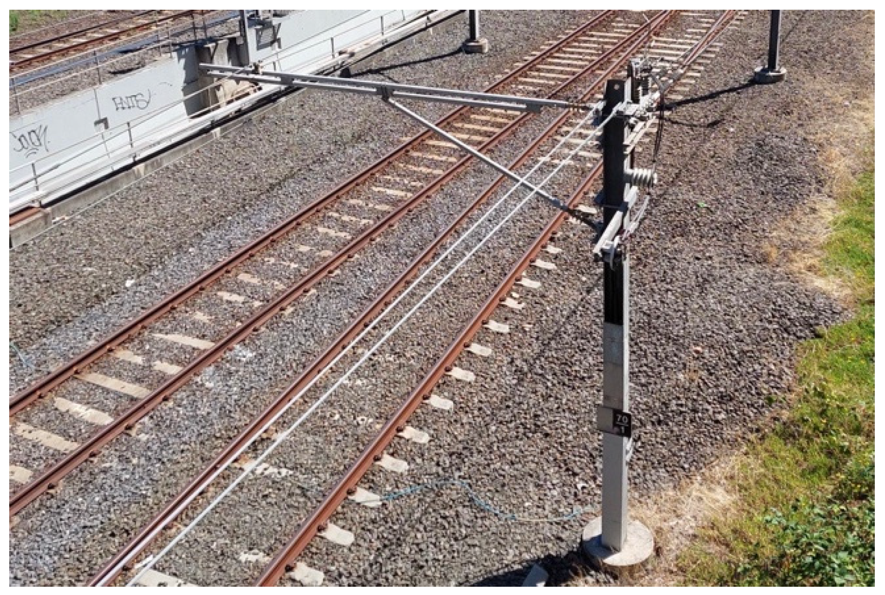
Single mast OWS are usually constructed from steel H-sections (called universal columns in Australia) with a fixed base. An example is shown in
Figure 3. The base fixity is provided either by a base plate and holding down bolts embedded in a reinforced concrete footing, or a long length of steel section potted in an augured hole with reinforced concrete surround. The catenary wire is supported by a cantilever jib via a suspension insulator. The jib is commonly clamped onto the H-section instead of permanent welding or bolting to facilitate adjustment of its elevation. Single mast OWS are typically used for a single-track arrangement. Common durability issues of single masts include corrosion, loss of grout/crack at base plate, and deviation from plumb.
3.1.2. Cantilever OWS
Historical cantilever OWS are riveted laced truss with a braced knee to enhance their bending strengths, as shown in
Figure 4a. In these riveted structures open sections such as angles, channels and flat plates are often used. The crevices between joined members accumulate moisture and are frequently susceptible to corrosion. Modern cantilever OWS (
Figure 4b,c) are typically made up of rectangular hollow sections. They are comprised of a vertical cantilever column and a horizontal beam with a vertical drop at its end. An end-plate connection between beam and column is commonly adopted to facilitate in-situ installation. The vertical drop is clamped onto the beam to allow in-situ adjustment of its position. Two dressing arms (one for the contact wire and one for the catenary wire) extend across one or two tracks in order to provide support to the overhead wirings over two tracks. Durability issues in addition to those in single masts include crevice corrosion between connecting plates (especially in riveted OWS), deflections on cantilever arms, etc.
3.1.3. Portal OWS
Portal OWS are simple portal frames which are often used to support overhead wirings in twin-track arrangements. Structural I-sections are typically selected as frame members. Wirings are supported by clamped vertical drops. Therefore, portal OWS provide better geometrical flexibility such as in curved tracks, track junctions, and at train stations. Sometimes “knees” at beam-to-column connections are provided to enhance structural strength. Out-of-plane stability is provided by fixity at their bases, similar to those in cantilever OWS.
Figure 5a shows a portal OWS is used in conjunction with cantilever OWS in a newly built rail line. Corrosion in locations where moisture accumulates, such as bottom flanges of I-sections and at base connection (
Figure 5b).
3.1.4. Walkway OWS
Walkway OWS are larger structures that provide easy access to signal hardware and/or feeder wirings, as maintenance may be frequent. Walkway OWS could be portal structures, cantilever structures but more commonly a truss type portal as shown in
Figure 6. Handrails and access ladder are installed to provide a safe work environment.
3.2. Design and Construction of OWS
In Australia, the modern design of OWS involves the loading specifications in AS1170 [
48], design of steel structures AS4100 [
49], design of concrete structures AS3600 [
50], design of platforms and walkway AS1657 [
51], design of piled foundation AS2159 [
52] and hot-dip galvanized coatings in AS/NZS4680 [
53]. In addition to these national standards, each state has its own governing body in rail and state-specific guidelines or manuals are followed. Generally, design loads on OWS include seven load cases and seven load combinations, as listed in
Table 1 and
Table 2. Load combinations LC1 to LC5 are strength limit states, LC6 and 7 are serviceability limit states and LC8 is a stability limit state [
54]. In a serviceability limit state, in-plane and out-of-plane deflection limits are imposed but the magnitudes may differ slightly across different jurisdictions. The stability limit state considers overturning of structure using a factor if 1.2 for forces causing overturn effect and 0.9 for forces causing stabilizing effect.
Construction of OWS is carried out by specialist contractors who are experienced in steel work fabrications and installations. Segments of OWS are fabricated off-site in shop environment and delivered to site for installation. Construction is facilitated by specialized trucks which have modified wheels to travel on tracks and are equipped with elevated platforms and cranes. Structural joints are fabricated to facilitate rapid bolting. In-situ bolting is preferred over welding for better construction efficiency and workmanship control. Structural members are galvanized in order to provide good durability under exposed condition. In case of replacement of old OWS, temporary suspension of train services is required. It is common to install new OWS in close proximity to a decommissioned one to facilitate relocation of existing wiring, as shown in
Figure 7.
3.3. Inspections and Assessments of Existing OWS
OWS are exposed structures and environmental effects accelerate their deterioration over time. A reliable train network requires proper inspections and assessment of these structures. The AS4292 Railway safety management [
55] provides the overarching requirements and Part 2 of the standard [
56] covers requirements on civil infrastructures. However, a standardized method of inspections or assessment criteria is unavailable, and the procedures are commonly an “in-house” practice, i.e., train companies have their own internal procedures to safeguard reliability of their assets. Detail procedures of inspection and assessment differ from company to company, but they can be divided into planned maintenance which is carried out on a regular time interval, and condition-based maintenance which is carried out only when necessary. Regardless of jurisdictions, maintenance work often follows similar considerations:
A historical archive is maintained, and information includes structural drawings, design loads, year of construction, failure histories, previous inspection reports and maintenance records, etc.
A planned inspection schedule, e.g., every two years.
Several “levels of inspections” are prescribed. An example is shown in
Table 3. A low-level inspection involves visual inspections without disruption to train service. Inspectors typically look for signs of deterioration such as corrosion, plumb deviation or deflection, loosening of bolts, cracks, erosion of soil around foundation, conditions of electrical fittings, nearby vegetations, etc. A score will be assigned to different components and recorded. If remedies are deemed required, the defects are further categorized into different priorities for scheduled maintenance. A significant defect will flag an urgent repair which may require suspension of train service. A poor result from a low-level inspection will trigger a high level of inspection.
A higher level of inspection requires engineering assessments by experienced engineers. The use of destructive or non-destructive testing to gather quantitative data is required. Assessment may include estimation of thickness loss due to corrosion, measurement of paint thickness, etc.
Once determined necessary, remedial works on existing OWS are determined by engineers. Remedial works such as application of surface coatings, replacements of foundations, partial replacement of structural members, or complete replacement of OWS structure.
Figure 8a shows an example of retrofitting of an OWS by replacement of foundation. Extensive spalling of concrete was observed in the original foundation and new reinforced concrete is cast around an existing laced column of a signal gantry.
Figure 8b shows partial replacement of corroded steel members in a signal gantry with new galvanized sections. The heavily corroded portion is patched up with a steel plate.
Although steel OWS are simple structures and their assessments are less complex than the assessment of steel bridges, due to the amount in a rail network a more scientific approach to assessment may deem more cost-effective. The authors have proposed a time-dependent structural reliability approach to assess OWS. Readers who are interested in this approach may refer to [
57].
4. Structural Assessment of a Century-Old OWS
The OWS described in this section is a twin-track riveted portal structure that belonged to a railway line approximately 250 m away from the seashore.
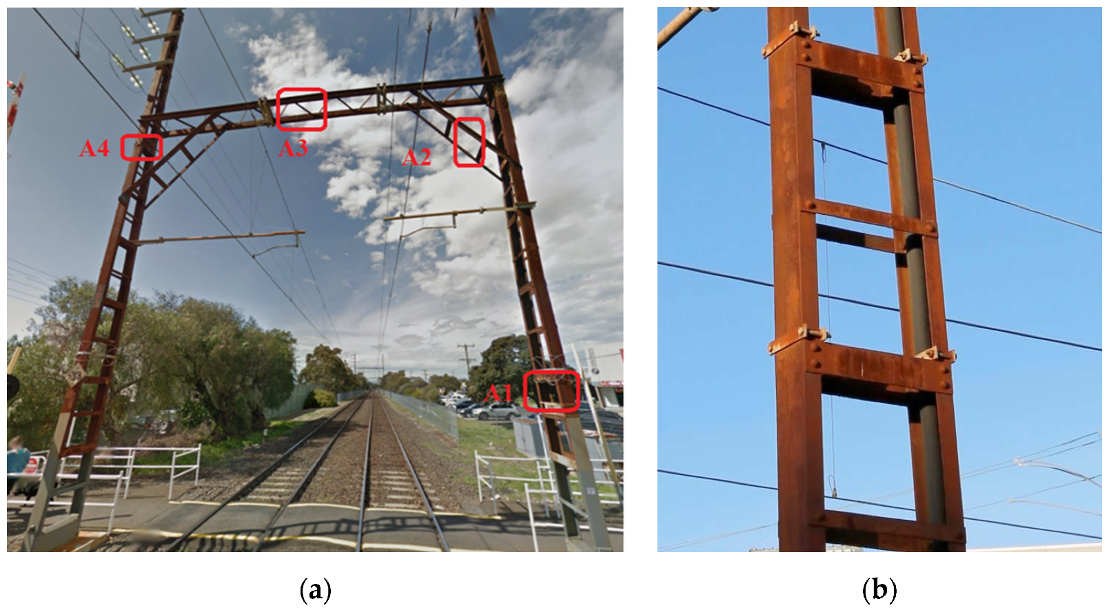
Figure 9a shows the OWS prior to its demolition. A 9.14 m (30′) long laced steel beam was elevated at 8.7 m (28′8″) above ground by two battened columns and carried centenary wires for two tracks. It also carried electricity transmission lines for power distribution. The OWS appeared to be unpainted except the bottom 2 m near the foundation. The age of the structure precedes the invention of weathering steel in the 1930s, however. The annotation represents the sampling locations, and
Figure 9b shows the construction of battened column. Vertical members of the battened columns were equal flange channels connected by horizontal steel plates. The structure was connected with rivets. The original structure was built in the 1910s during the electrification of the railway, making it approximately a century old at the time of this writing. The manufacturer was uncertain but given its age the steel members were probably imported from Britain. The material specifications and maintenance records could not be identified. The structure was decommissioned in an upgrade project in which most of the OWS in the same train line were replaced. The bottom 2 m segments of the battened columns were covered by paint.
Figure 10 shows the original drawing dated in the 1910s.
4.1. Visual Inspections
The decommissioned OWS were cut into segments and stockpiled in a scrap metal yard, which allowed the authors to carry out a close examination. An identification number on the structure allowed the authors to identify this structure to its original drawing. The bottom 2 m of the battened column were painted, and this portion was in good condition as indicated in
Figure 11a. Immediately above the paint, however, significant deterioration on batten plates is observed. The severity varied significantly: one particular batten plate was corroded through, while the next plate at the same elevation appeared intact, as shown in
Figure 11b. The rivets observed were intact and tight. Crevice corrosion frequently occurred at junctions between riveted parts where moisture accumulated. Samples of the structures were taken to further laboratory testing.
4.2. Tensile Tests
Test coupons were taken from a battened column, and bridge and knee brace of the examined structure, as indicated in
Figure 9a. Dimensions according to AS1391 [
58] were followed. The true stress versus strain diagram is shown in
Figure 12 and
Table 4 summarized the results. Yield stresses of specimens were very close to modern-day Grade 250, with ultimate stress in excess of 540 MPa (current standard requirement is 410 MPa) [
59]. All samples exhibited good ductility.
Corrosion depths were estimated by comparing original thickness and measured thickness of samples collected when rust was removed (there was no paint on the samples). An ultrasonic thickness gauge was used for this purpose. To obtain meaningful measurements, surface rust must be removed [
60] and it was carried out manually and the specimens were cleaned and degreased. Care was taken to ensure only the rust was removed.
Figure 13 shows the sample before and after rust removal. Twelve measurements were made on each sample and corrosion depths were estimated by comparing to historical nominal values. Results are summarized in
Table 5. Percentage loss showed a great variation. The largest material loss was found in steel angles sourced from the knee brace, apparently attributed to moisture accumulation. It was impossible to calibrate any corrosion model with measurement at a single point in time, and a general rate of corrosion is inconclusive given the variability in observed results. However, corrosion depths were less than those predicted by AS4312, for which it predicted 2.5–8.0 mm at category C3/C4 medium to high corrosivity [
61].
4.3. Riveted Joints
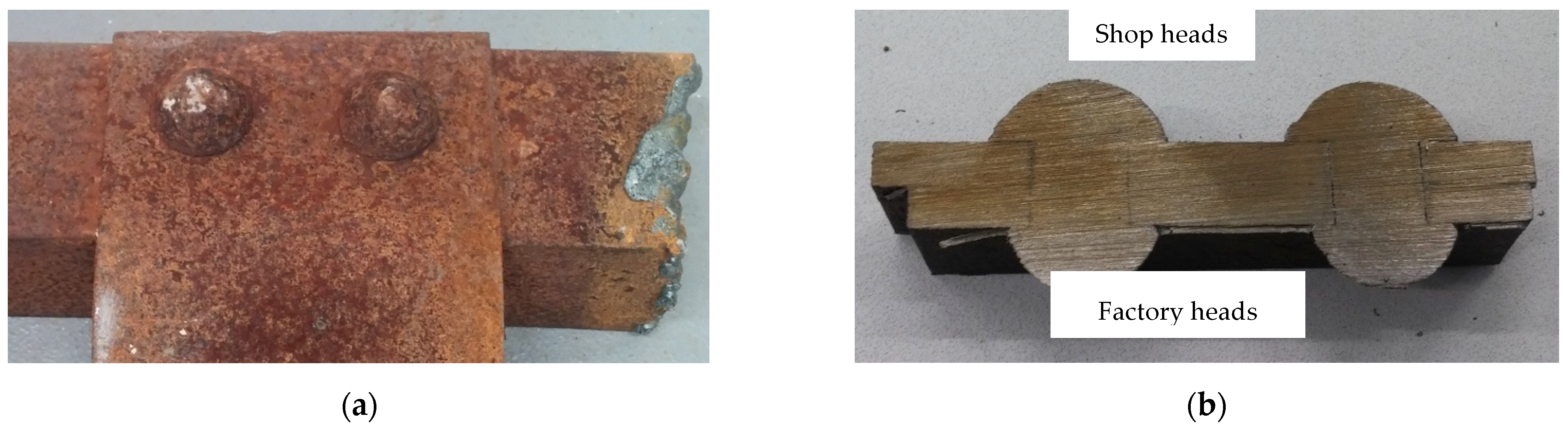
A rivet joint from a knee brace was cut through for examination, as shown in
Figure 14a. The surface of the rivets was heavily rusted, but the connection was tight. The connection was cut through, exposing its cross-section as shown in
Figure 14b. The 1/8″ (3.175 mm) hole clearance had been completely closed by forging. The rivets clamped two connecting plates tightly and corrosion was not evident. The shop heads could be readily identified by its imperfect shape, and they were larger than the factory heads. Radiographic images were taken, and a sample image is shown in
Figure 14c. No internal crack was identified in any sample collected. It indicates that the rivets performed satisfactorily and eliminated air and moisture even after 100 years of usage.
4.4. Scanning Electronic Microscopy and Energy Dispersive X-ray
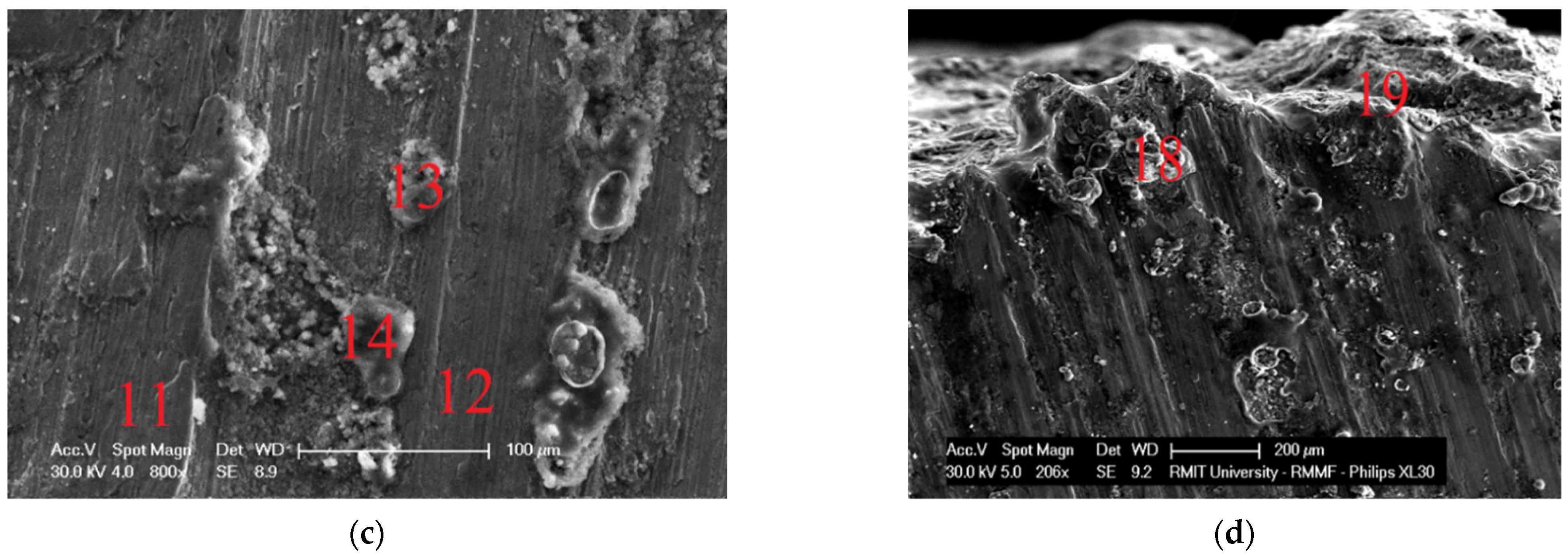
Scanning Electronic Microscopy (SEM) was carried out on steel specimens taken from the battened column using a Philips XL30 SEM. The microscope had a specimen stage of 50 mm × 50 mm, which was limited by the size of its vacuum chamber. The microscope is also equipped with an energy dispersive X-ray (EDX) detector. The samples were cut into approximately 20 mm × 20 mm.
Figure 15a,b show typical images taken on the rust surface. The numbers indicate on the image were the sites where EDX was carried out. Rust products of rough and loose structure were visible. Results of EDX taken on rust surface revealed that, in addition to iron and oxygen, traces of lead and arsenic were found. It indicated that certain kinds of lead-based and arsenic-based corrosion inhibitors were applied.
Figure 15c,d show images taken on a cut surface. In
Figure 15c, deposits of corrosion products have grown, and straight grain boundaries are visible.
Figure 15d shows an image taken on the edge of the cross-section. EDX results measured on the cross-section surface revealed impurities including silicon (max. 0.3%), manganese (max 0.5%) and silicon (max. 0.3%) were detected. However, their concentrations were low and within requirements of Grade 250 at modern-day standard (AS3678 [
59]). However, the concentration of sulphur (max. 0.5%) exceeded the limits in two measurement locations.
5. Conclusions
Rail overhead wiring structures (OWS) are an essential part of an electric rail network. They provide support to overhead power wires to power train services. Although they are simple steel structures, a rail network may consist of tens of thousands of these OWS and they represent a large capital expenditure. This article presents a review of structural aspects of OWS in Australia, which has evolved over the 100-year period since electrification began. Discussion includes their typical structural forms, design, construction, assessment and maintenance. This article then describes an assessment carried out on a century-old, riveted OWS. The structure was located approximately 250 m from the seashore and severe corrosion occurred in the structure. The structure was decommissioned in a railway upgrade project which allowed detailed assessments to be carried out. Due to its age, the original material grade and record of maintenance was unknown. Tensile tests on samples indicated yield strengths were very close to modern-day Grade 250 steel, and ultimate stress exceeded 540 MPa. All samples showed good ductility. Depending on the location of samples were taken from, corrosion depths showed great variations and conclusive value of corrosion rate cannot be made. The measurement of corrosion depth ranged from 0.15 mm (1.9% depth) to completely rust-through. Rivet joint samples were examined and revealed that they remained structurally robust and tightly clamp connecting parts together after 100 years of service. Corrosion inside the joints was not identified and internal cracks were not detected via radiographic imaging. SEM and EDX analyses were conducted, and results indicated that lead and arsenic-based corrosion inhibitors had been applied on the metal surface, and impurities in the material were low and generally met modern-day standards. The study gives an insight into the steel material and construction during the era of electrification of rail a century began. Other than severe corrosion in certain locations, the assessed OWS remained structurally sound. It gives confidence to the community as many similar overhead wiring structures are still being used today.
Author Contributions
Conceptualization, B.H. and R.W.K.C.; methodology, B.H. and R.W.K.C.; experimental investigation, B.H.; writing, R.W.K.C.; visualization, B.H. and R.W.K.C. All authors have read and agreed to the published version of the manuscript.
Funding
This research was partially funded by Metro Trains Melbourne.
Institutional Review Board Statement
Not applicable.
Informed Consent Statement
Not applicable.
Data Availability Statement
Not applicable.
Conflicts of Interest
The authors declare no conflict of interest.
References
- Nyberg, F.; Pollard, R. Network Rail Guide to Overhead Electrification; Alan Baxter & Associates LLP: London, UK, 2015. [Google Scholar]
- Department of Transport and Main Roads. Independent Audit into the Reliability of Queensland Rail’s South-East Queensland Network; Final Report; Department of Transport and Main Roads: Brisbane, Australia, 2012.
- Overhead Wiring Standards for Design and Construction; Standard T HR EL 08012 ST; Transport Asset Standards Authority: Sydney, NSW, Australia, 2018.
- Hisa, T.; Kanaya, M.; Sakai, M.; Hamaoka, K. Rail and Contact Line Inspection Technology for Safe and Reliable Railway Traffic. Hitachi Rev. 2012, 61, 325–330. [Google Scholar]
- Hofler, H.; Dambacher, M.; Dimopoulos, N.; Jetter, V. Monitoring and inspecting overhead wires and supporting structures. In Proceedings of the IEEE Intelligent Vehicles Symposium, Parma, Italy, 14–17 June 2004; IEEE: Piscataway, NJ, USA, 2004. [Google Scholar]
- Arastounia, M. Automated Recognition of Railroad Infrastructure in Rural Areas from LIDAR Data. Remote Sens. 2015, 7, 14916–14938. [Google Scholar] [CrossRef] [Green Version]
- Chen, L.; Xu, C.; Lin, S.; Li, S.; Tu, X. A Deep Learning-Based Method for Overhead Contact System Component Recognition Using Mobile 2D LiDAR. Sensors 2020, 20, 2224. [Google Scholar] [CrossRef] [PubMed] [Green Version]
- Harter, M.; Schipper, T.; Zwirello, L.; Ziroff, A.; Zwick, T. Detection of Overhead Contact Lines with a 2D-Digital-Beamforming Radar System for Automatic Guidance of Trolley Trucks. Int. J. Veh. Technol. 2013, 2013, 914351. [Google Scholar] [CrossRef] [Green Version]
- Puschmann, R.; Wehrhahr, D. Ultrasonic measurement of contact wire position. eb—Elektrische Bahnen 2011, 109, 323–324. [Google Scholar]
- Chen, P.; Xu, C.; Li, Z.; Xu, Z. Design and implementation of non-contact detection system for catenary based on double linear array cameras. In Proceedings of the 5th International Conference on Computer-Aided Design, Manufacturing, Modeling and Simulation, Busan, Korea, 22–23 April 2017. [Google Scholar]
- Yu, L.; Gao, S.; Zhang, D.; Kang, G.; Zhan, D.; Roberts, C. A Survey on Automatic Inspections of Overhead Contact Lines by Computer Vision. IEEE Trans. Intell. Transp. Syst. 2021, 1–22. [Google Scholar] [CrossRef]
- Aydin, I.; Karakose, M.; Akin, E. Anomaly detection using a modified kernel-based tracking in the pantograph-catenary system. Expert Syst. Appl. 2015, 42, 938–948. [Google Scholar] [CrossRef]
- Efanov, D.; Sedykh, D.; Osadchy, G.; Barch, D. Permanent monitoring of railway overhead catenary poles inclination. In Proceedings of the 2017 IEEE East-West Design & Test Symposium, Novi Sad, Serbia, 29 September–2 October 2017. [Google Scholar]
- Efanov, D.; Osadchy, G.; Sedykh, D.; Pristensky, D.; Barch, D. Monitoring system of vibration impacts on the structure of overhead catenary of high-speed railway lines. In Proceedings of the 2016 IEEE East-West Design & Test Symposium, Yerevan, Armenia, 14–17 October 2016. [Google Scholar]
- Boffi, P.; Cattaneo, G.; Amoriello, L.; Barberis, A.; Bucca, G.; Bocciolone, M.F.; Collina, A.; Martinelli, M. Optical Fiber Sensors to Measure Collector Performance in the Pantograph-Catenary Interaction. IEEE Sens. J. 2009, 9, 635–640. [Google Scholar] [CrossRef]
- Massat, J.P.; Nguyen Tajan, T.M.L.; Maitournam, H.; Balmès, E. Fatigue analysis of catenary contact wires for high speed trains. In Proceedings of the 9th World Congress on Railway Research, Lille, France, 22–26 May 2011. [Google Scholar]
- Wu, T.X.; Brennan, M.J. Dynamic stiffness of a railway overhead wire system and its effect on pantograph-catenary system dynamics. J. Sound Vib. 1999, 219, 483–502. [Google Scholar] [CrossRef]
- Arnold, M.; Simeon, B. Pantograph and catenary dynamics: A benchmark problem and its numerical solution. Appl. Numer. Math. 2000, 34, 345–362. [Google Scholar] [CrossRef]
- Park, T.-J.; Han, C.-S.; Jang, J.-H. Dynamic sensitivity analysis for the pantograph of a high-speed rail vehicle. J. Sound Vib. 2003, 266, 235–260. [Google Scholar] [CrossRef]
- Gregori, S.; Tur, M.; Nadal, E.; Aguado, J.; Fuenmayor, F.; Chinesta, F. Fast simulation of the pantograph-catenary dynamic interaction. Finite Elem. Anal. Des. 2017, 129, 1–13. [Google Scholar] [CrossRef] [Green Version]
- Benet, J.; Cuartero, F.; Rojo, T.; Tendero, P.; Arias, E. A Dynamic Model for the Study and Simulation of the Pantograph–Rigid Catenary Interaction with an Overlapping Span. Appl. Sci. 2021, 11, 7445. [Google Scholar] [CrossRef]
- Nåvik, P.; DeRosa, S.; Rønnquist, A. Development of an index for quantification of structural dynamic response in a railway catenary section. Eng. Struct. 2020, 222, 111154. [Google Scholar] [CrossRef]
- Wu, J. Pantograph and Contact Line System; Academic Press: London, UK, 2018. [Google Scholar]
- Kia, S.H.; Bartolini, F.; Mpanda-Mabwe, A.; Ceschi, R. Pantograph-catenary interaction model comparison. In Proceedings of the 36th Annual Conference on IEEE Industrial Electronics Society, Glendale, AZ, USA, 7–10 November 2010; IEEE: Piscataway, NJ, USA, 2010. [Google Scholar]
- Bruni, S.; Ambrosio, J.; Carnicero, A.; Cho, Y.H.; Finner, L.; Ikeda, M.; Kwon, S.Y.; Massat, J.-P.; Stichel, S.; Tur, M.; et al. The results of the pantograph-catenary interaction benchmark. Veh. Syst. Dyn. 2015, 53, 412–435. [Google Scholar] [CrossRef]
- Song, Y.; Antunes, P.; Pombo, J.; Liu, Z. A methodology to study high-speed pantograph-catenary interaction with realistic contact wire irregularities. Mech. Mach. Theory 2020, 152, 103940. [Google Scholar] [CrossRef]
- Zhang, W.; Zou, D.; Tan, M.; Zhou, N.; Li, R.; Mei, G. Review of pantograph and catenary interaction. Front. Mech. Eng. 2018, 13, 311–322. [Google Scholar] [CrossRef]
- Avila-Sanchez, S.; Lopez-Garcia, O.; Cuerva, A.; Meseguer, J. Assesment of the transverse galloping stability of a railway overhead located above a railway bridge. Int. J. Mech. Sci. 2017, 131–132, 649–662. [Google Scholar] [CrossRef]
- Song, Y.; Liu, Z.; Wang, H.; Zhang, J.; Lu, X.; Duan, F. Analysis of the galloping behaviour of an electrified railway overhead contact line using the non-linear finite element method. Proc. Inst. Mech. Eng. Part F J. Rail Rapid Transit 2018, 232, 2339–2352. [Google Scholar] [CrossRef]
- Kraus, M.; Hagedorn, P. Aeolian vibrations: Wind energy input evaluated from measurements on an energized transmission line. IEEE Trans. Power Deliv. 1991, 6, 1264–1270. [Google Scholar] [CrossRef]
- Song, Y.; Liu, Z.; Wang, H.; Lu, X.; Zhang, J. Nonlinear analysis of wind-induced vibration of high-speed railway catenary and its influence on pantograph–catenary interaction. Veh. Syst. Dyn. 2016, 54, 723–747. [Google Scholar] [CrossRef]
- Song, Y.; Zhang, M.; Wang, H. A Response Spectrum Analysis of Wind Deflection in Railway Overhead Contact Lines Using Pseudo-Excitation Method. IEEE Trans. Veh. Technol. 2021, 70, 1169–1178. [Google Scholar] [CrossRef]
- Sanchez-Rebollo, C.; Velez, E.; Jimenez-Octavio, J.R. Numerical characterization of real railway overhead cables. Wind Struct. Int. J. 2015, 21, 105–117. [Google Scholar] [CrossRef]
- Chu, W.; Song, Y.; Liu, Z. A Comparative Study on the Wind Deflection of Railway Overhead Contact Line Based on Empirical Formula and Finite Element Approach. Shock Vib. 2021, 2021, 5737457. [Google Scholar] [CrossRef]
- Ngamkhanong, C.; Kaewunruen, S.; Calçada, R.; Martin, R. Failure of Overhead Line Equipment (OHLE) Structure under Hurricane; Springer: Cham, Switzerland, 2019; pp. 54–63. [Google Scholar]
- Ngamkhanong, C.; Kaewunruen, S.; Baniotopoulos, C.; Papaelias, M. Crossing Phenomena in Overhead Line Equipment (OHLE) Structure in 3D Space Considering Soil-Structure Interaction. IOP Conf. Ser. Mater. Sci. Eng. 2017, 245, 32047. [Google Scholar] [CrossRef]
- Ngamkhanong, C.; Kaewunruen, S.; Baniotopoulos, C. Far-Field Earthquake Responses of Overhead Line Equipment (OHLE) Structure Considering Soil-Structure Interaction. Front. Built Environ. 2018, 4, 35. [Google Scholar] [CrossRef]
- Consilvio, A.; Di Febbraro, A.; Meo, R.; Sacco, N. Risk-based optimal scheduling of maintenance activities in a railway network. EURO J. Transp. Logist. 2019, 8, 435–465. [Google Scholar] [CrossRef]
- Consilvio, A.; Di Febbraro, A.; Sacco, N. A Rolling-Horizon Approach for Predictive Maintenance Planning to Reduce the Risk of Rail Service Disruptions. IEEE Trans. Reliab. 2021, 70, 875–886. [Google Scholar] [CrossRef]
- Macedo, R.; Benmansour, R.; Artiba, A.; Mladenović, N.; Urošević, D. Scheduling preventive railway maintenance activities with resource constraints. Electron. Notes Discret. Math. 2017, 58, 215–222. [Google Scholar] [CrossRef]
- Bouillaut, L.; Francois, O.; Dubois, S. A Bayesian network to evaluate underground rails maintenance strategies in an automation context. Proc. Inst. Mech. Eng. Part O J. Risk Reliab. 2013, 227, 411–424. [Google Scholar] [CrossRef]
- Sancho, L.C.B.; Braga, J.A.P.; Andrade, A.R. Optimizing Maintenance Decision in Rails: A Markov Decision Process Approach. ASCE-ASME J. Risk Uncertain. Eng. Syst. Part A Civ. Eng. 2021, 7, 04020051. [Google Scholar] [CrossRef]
- Macchi, M.; Garetti, M.; Centrone, D.; Fumagalli, L.; Pavirani, G.P. Maintenance management of railway infrastructures based on reliability analysis. Reliab. Eng. Syst. Saf. 2012, 104, 71–83. [Google Scholar] [CrossRef]
- Peng, F.; Ouyang, Y.; Somani, K. Optimal routing and scheduling of periodic inspections in large-scale railroad networks. J. Rail Transp. Plan. Manag. 2013, 3, 163–171. [Google Scholar] [CrossRef]
- Salierno, G.; Morvillo, S.; Leonardi, L.; Cabri, G. An architecture for predictive maintenance of railway points based on big data analytics. In Advanced Information Systems Engineering Workshops, Proceedings of the International Conference on Advanced Information Systems Engineering, Grenoble, France, 8–12 June 2020; Springer: Cham, Switzerland, 2020. [Google Scholar]
- Lopes Gerum, P.C.; Altay, A.; Baykal-Gürsoy, M. Data-driven predictive maintenance scheduling policies for railways. Transp. Res. Part C Emerg. Technol. 2019, 107, 137–154. [Google Scholar] [CrossRef]
- Lasisi, A.; Attoh-Okine, N. Principal components analysis and track quality index: A machine learning approach. Transp. Res. Part C Emerg. Technol. 2018, 91, 230–248. [Google Scholar] [CrossRef]
- AS1170; Structural Design Actions General Principles. Standards Australia: Sydney, Australia, 2002.
- AS4100; Steel Structures. Standards Australia: Sydney, Australia, 2020.
- AS3600; Concrete Structures. Standards Australia: Sydney, Australia, 2018.
- AS1657; Fixed Platforms, Walkways, Stairways and Ladders—Design, Construction and Installation. Standards Australia: Sydney, Australia, 2018.
- AS2159; Piling—Design and Installation. Standards Australia: Sydney, Australia, 2009.
- AS/NZS4680; Hot-Dip Galvanized (Zinc) Coatings on Fabricated Ferrous Articles. Standards Australia: Sydney, Australia, 2006.
- Honor, P. Design of Overhead Wiring Structures and Signal Gantries; RailCorp NSW: Sydney, Australia, 2015. [Google Scholar]
- AS4292.1; Railway Safety Management Part 1: General Requirements. Standards Australia: Sydney, Australia, 2006.
- AS4292.2; Railway Safety Management—Track, Civil and Electrical Infrastructure. Standards Australia: Sydney, Australia, 2006.
- Hu, B.; Chan, R.W.K. Time-dependent reliability analysis of railway overhead structures. SN Appl. Sci. 2019, 1, 1279. [Google Scholar] [CrossRef] [Green Version]
- AS1391; Metallic Materials—Tensile Testing at Ambient Temperature. Standards Australia: Sydney, Australia, 2007.
- AS3678; Structural Steel—Hot-Rolled Plates, Floorplates and Slabs. Standards Australia: Sydney, Australia, 2016.
- Damgaard, N.; Walbridge, S.; Hansson, C.; Yeung, J. Corrosion protection and assessment of weathering steel highway structures. J. Constr. Steel Res. 2010, 66, 1174–1185. [Google Scholar] [CrossRef]
- AS4312; Atmospheric Corrosivity Zones in Australia. Standards Australia: Sydney, Australia, 2019.
Figure 1.
Schematic diagram of rail overhead wiring.
Figure 1.
Schematic diagram of rail overhead wiring.
Figure 2.
Weight stack and pulley system.
Figure 2.
Weight stack and pulley system.
Figure 3.
Single mast OWS.
Figure 3.
Single mast OWS.
Figure 4.
(a) historical riveted cantilever OWS, (b) a newly built cantilever OWS and (c) its foundation.
Figure 4.
(a) historical riveted cantilever OWS, (b) a newly built cantilever OWS and (c) its foundation.
Figure 5.
(a) Newly built cantilever and portal OWS; (b) Base plate of an old portal OWS.
Figure 5.
(a) Newly built cantilever and portal OWS; (b) Base plate of an old portal OWS.
Figure 6.
A signal gantry.
Figure 6.
A signal gantry.
Figure 7.
Construction of a new OWS next to a decommissioned one.
Figure 7.
Construction of a new OWS next to a decommissioned one.
Figure 8.
Retrofits of an existing OWS. (a) New concrete foundation, (b) Partial replacement of steel truss members.
Figure 8.
Retrofits of an existing OWS. (a) New concrete foundation, (b) Partial replacement of steel truss members.
Figure 9.
(a) Assessed OWS prior to demolition, (b) battened column.
Figure 9.
(a) Assessed OWS prior to demolition, (b) battened column.
Figure 10.
Original drawing in the 1910s.
Figure 10.
Original drawing in the 1910s.
Figure 11.
Demolished battened column. (a) bottom section, (b) Mid-section.
Figure 11.
Demolished battened column. (a) bottom section, (b) Mid-section.
Figure 12.
True stress-strain behavior from tensile tests.
Figure 12.
True stress-strain behavior from tensile tests.
Figure 13.
Sample before and after rust removal.
Figure 13.
Sample before and after rust removal.
Figure 14.
Riveted joint (a) sample as collected, (b) cut-through section and (c) radiographic image.
Figure 14.
Riveted joint (a) sample as collected, (b) cut-through section and (c) radiographic image.
Figure 15.
SEM images. (a) and (b) surface and (c) and (d) cross section.
Figure 15.
SEM images. (a) and (b) surface and (c) and (d) cross section.
Table 1.
Load cases of OWS design.
Table 1.
Load cases of OWS design.
| Load Case | Comments |
|---|
| Dead loads | Self-weight of structure, electrical fittings and insulators, static weight of wires, stack weights, etc. |
| Live loads | OWS are non-trafficable and thus not subjected to any live loads. However, an allowance for construction load which represent the weight of a person on the contact wire is required. |
| Radial loads | Radial loads are produced by geometrical and tension effects caused by wiring. i.e., when wiring changes directions. At termination points, OWS is anchored, and the reaction forces produced by guy-wire is also considered. |
| Wind loads on wire | Overhead wiring may span up to 70 m and wind forces accumulated on the wiring are transferred to the OWS. Wind forces based on 100-year return period is required for new OWS designs. |
Wind loads on structure
(x-direction) | OWS are exposed structures and thus need to be designed against wind actions. Values of wind force depend on local topography, importance level and design return-period. Modern OWS are commonly designed with a 100-year design life. |
Wind loads on structure
(y-direction) |
| Wind loads on structure (45°) |
Table 2.
Load combinations of OWS design.
Table 2.
Load combinations of OWS design.
| Load Combinations | Comments |
|---|
| LC1 | 1.35 × (Dead load + radial load) |
| LC2 | 1.2 × (Dead load + radial load) + 1.5 × Live load |
| LC3 | 1.2 × (Dead load + radial load) + Wind load on wire and structure (x-direction) |
| LC4 | 1.2 × (Dead load + radial load) + 0.5 × Wind load on wire + Wind load on structure (45°) |
| LC5 | 1.2 × (Dead load + radial load) + Wind load on structure (y-direction) |
| LC6 | Dead load + radial load |
| LC7 | 0.65 (wind load on wire + wind load on structure x-direction) |
| LC8 | Out of plane restoring moment/overturning moment > 1.2 |
Table 3.
Inspection levels.
Table 3.
Inspection levels.
| Inspection Level | Purpose |
|---|
| General observation | To identify safety hazards |
| Level 1 Visual inspection | To confirm if the structure is safe for operational purposes |
| Level 2 Detailed visual inspection | To identify and prioritise maintenance needs |
| Level 3 Engineering assessment | To provide a comprehensive load-carrying capacity rating |
| Special inspection | To monitor specific defects/Reassess defects |
Table 4.
Experimental result of the tensile tests.
Table 4.
Experimental result of the tensile tests.
| Sample | A1 | A2 | A3 | A4 | Mean |
|---|
| Yield stress [MPa] | 271.1 | 258.72 | 264.81 | 260.37 | 263.75 |
| Ultimate stress [MPa] | 559.93 | 584.38 | 580.28 | 543.42 | 567.00 |
| Max strain | 0.277 | 0.353 | 0.355 | 0.306 | 0.323 |
Table 5.
Corrosion depth measurements.
Table 5.
Corrosion depth measurements.
| Sample | Original Thickness [mm] | Measured
Thickness [mm] | Corrosion
Depth [mm] | % Loss |
|---|
| A1 | 10.92 | 9.41 | 1.51 | 13.8 |
| A2 | 10.92 | 9.53 | 1.39 | 12.7 |
| P1 | 7.94 | 7.79 | 0.15 | 1.9 |
| P2 | 7.94 | 7.51 | 0.43 | 5.4 |
| C1 | 9.14 | 8.43 | 0.71 | 7.8 |
| Publisher’s Note: MDPI stays neutral with regard to jurisdictional claims in published maps and institutional affiliations. |
© 2022 by the authors. Licensee MDPI, Basel, Switzerland. This article is an open access article distributed under the terms and conditions of the Creative Commons Attribution (CC BY) license (https://creativecommons.org/licenses/by/4.0/).


