Article

Mechanical Characterization of AISI 316L Samples Printed Using Material Extrusion

Department of Management, Information and Production Engineering, University of Bergamo, Via Pasubio 7/b, 24044 Dalmine, BG, Italy
*
Author to whom correspondence should be addressed.
Appl. Sci. 2022, 12(3), 1433; https://doi.org/10.3390/app12031433
Submission received: 22 December 2021 / Revised: 26 January 2022 / Accepted: 27 January 2022 / Published: 28 January 2022
(This article belongs to the Topic Additive Manufacturing)

Abstract

:
The main additive manufacturing (AM) methods to produce metal components are laser powder bed fusion and directed energy deposition, which are energy-intensive, time-consuming, and require high investment costs. An economical alternative is based on a new feedstock comprising a homogenous mixture of sinterable metal powders and a multi-component binder system. This feedstock enables the creation of metal components printed using the material extrusion (ME) technique. In this study, mechanical characterization of AISI 316L samples is conducted to identify the mechanical properties of parts printed using the metal ME process. The test results indicate an average maximum tensile stress of 426.6 ± 23.7 MPa and an elongation at break of 36%. Both the tensile and compressive yield stresses are approximately 150 MPa, demonstrating a symmetric response to the two opposite types of uniaxial loads. Rockwell B and Vickers hardness tests confirm the uniform behavior of the tested material. An X-ray diffraction analysis is conducted to assess the crystallographic structure of the ME 316L samples compared to that of the monolithic material. According to our study results, metal ME seems to be a promising technology to produce non-critical metallic parts that require good mechanical properties, good corrosion resistance, and complex shapes such as chemical tanks, heat exchangers, and medical instruments.

1. Introduction

The term additive manufacturing (AM) was coined in the 1990s to describe a new technology capable of manufacturing 3D components through a layer-by-layer deposition. According to ISO/ASTM 52900:2017 [1], AM is “the process of joining materials to make parts from 3D model data, usually layer upon layer, as opposed to subtractive and formative manufacturing technologies”.
Material extrusion (ME) is one of the most widely used AM technologies owing to its simplicity and low cost. This technique forces the extrusion material through a nozzle, which follows a predetermined path to build the component onto a build platform, layer upon layer. In the ME process, extruded materials are generally thermoplastic filaments with poor mechanical properties [2,3,4,5,6]. In general, parts manufactured using ME technology are excellent for prototyping and visualization purposes; however, they are rarely used for load-bearing applications owing to their lack of strength. This technical issue has limited the use of ME in mechanical applications. Extensive research is underway to improve the mechanical properties of ME components and thereby extend the applications of this technology.
Fiber-reinforced polymers have been investigated for decades owing to their tailored material properties and high specific strength. Fiberglass and carbon are the most widely used fibers in combination with a polymer matrix. The polymers hold and protect the fibers and transfer the load to the reinforcement, while fibers support the load by providing excellent resistance to the structure. A clear improvement in the ultimate tensile strength (UTS) of polymeric samples reinforced with fiberglass and carbon fibers is presented in [7,8].
Particular attention is also given to the use of filaments containing metal powders, which allow the manufacturing of metal parts with improved properties compared with those of polymer composites. A few studies have been conducted on the reinforcement of polymeric filaments with metallic particles. Hwang et al. [9] stated that the tensile strength of specimens decreased with an increase in the copper and iron contents in the thermoplastic filaments. Likewise, Ryders et al. [10] confirmed the deterioration of the mechanical properties of samples with the addition of type 420 stainless steel particles. In [11], an increase in the volume fraction of iron particles reduced the fracture energy. Furthermore, the authors indicated that the variations in the tensile strength and tensile elongation were strongly dependent on the size of the metal particles. Thus, a smaller particle size of the composite generated a larger tensile elongation at break but with a degradation in the tensile strength.
Polymer–metal composites reduce the mechanical performance owing to the difficulty in achieving uniform particle distribution and strong adhesion between the metal powders and polymer matrix. Poor adhesion generates large voids at the interfaces between the particles and matrix, which induce cracks upon loading. The bending behavior of parts printed with the metal–polymer blends was not adversely affected by the separation of the filler from the polymer matrix during the test. Nabipour et al. [12] performed flexural strength tests on polyethylene–copper samples, demonstrating that the addition of metal particles increased the maximum flexural strength up to 19.41 MPa. Butt et al. [13] enhanced the mechanical properties of specimens by interlacing copper mesh layers within a polymer matrix during the tests. The tensile strength, flexural strength, and Rockwell hardness slightly improved in comparison to those of the polymeric samples. Similarly, Fafenrot et al. [14] pointed out that the mechanical properties of objects printed with metal–polymer blends were compared to common PLA-printed objects.
Shaping, debinding, and sintering [15] is a promising multi-step ME process that overcomes the limitations associated with the poor mechanical properties of highly filled polymeric filaments. The shaping phase is performed with filaments characterized by a homogenous mixture of sinterable metal powders and a multi-component binder system. The binder fraction is removed from the printed part through a debinding step using solvents and/or thermal debinding [16]. Lastly, the sintering phase provides interparticle bonding that leads to near full densification through a thermal cycle performed below the melting temperature [17]. The thermal treatment phases improve the mechanical properties of the metal components, achieving values comparable to those typical of the metal base material. To date, few studies have been conducted on the mechanical properties of metal parts fabricated via ME and sintering. Liu et al. [18] reported that the average tensile strength of 316L stainless steel parts printed via ME was 441 ± 27 MPa and the Vickers hardness on average was approximately 145 ± 6.7 HV. Similarly, the 316L-material-extruded parts in [19] exhibited a yield strength of 167 MPa, a UTS of 436 MPa, and a Rockwell (B Scale) hardness value of 60 HRB. Damon et al. [20] analyzed the mechanical anisotropic performance of 316L samples printed via ME. Yield strength and UTS were not affected by build orientation; however, a correlation between the overall porosity and mechanical performance was apparent. Conversely, in [21], the authors demonstrated the anisotropy of the tensile properties of the specimens due to the presence of segregated binder domains in the filaments that remained as oriented voids after shaping and sintering phases. Henry et al. [22] confirmed a significant dependency between the building orientation of the layers and the yield strength and UTS of the specimens.
In contrast, Gong et al. [23] analyzed the mechanical properties of metal samples fabricated using two different AM techniques. The results of these tests indicated that the ME 316L samples had lower yield strength, UTS, and elastic modulus compared to those of 316L samples fabricated using the laser powder bed fusion technique. Similarly, in [24], the authors tested 17-4PH ME samples and found that Young’s modulus, maximum stress, and strain at break were 100%, 66%, and 16%, respectively, of the values of the specimens produced using laser sintering and traditional manufacturing methods [25,26].
An improvement in the mechanical properties of the metal-ME specimens could be achieved by an appropriate heat treatment following the sintering step. Abe et al. [27] enhanced the mechanical properties of 17-4PH samples by adding an aging treatment (condition H900). In their tests, the tensile strength of the specimens improved from 880 to 1140 MPa after the solution and aging treatments.
In the present work, an innovative multi-component filament highly filled with 316L stainless steel powder was used to shape the samples for subsequent mechanical testing. The objective of this study is to provide an overall mechanical characterization of debinded and sintered specimens in comparison with the monolithic AISI 316L material to expand the technical feasibility of this promising ME alternative for the manufacture of components with high added value and good mechanical characteristics utilizing low-cost equipment.

2. Materials and Methods

2.1. Equipment and Material

The testing samples were fabricated using a ME polymeric machine, Ultimaker 5S, equipped with a direct drive extruder with a hardened steel nozzle CC0.6 of diameter 0.6 mm, which was the smallest nozzle diameter, limiting the clogging problem. A filament with a diameter of 2.85 mm, provided by BASF (Ultrafuse 316L), was used. This is an innovative filament that is made up of 316L austenitic stainless-steel powders (90 wt%), evenly distributed in a polymeric matrix composed of polyoxymethylene (POM) and polyolefin. The immobilization of the metal particles and the uniform distribution of the metal within the binder matrix allow for safe and simple handling. The parts are built up layer upon layer from a moldable material, with the polymer content of the filament acting as a binder. The main polymer content (primary binder) was removed from the so-called green part through a catalytic and thermal debinding process at 120 °C with HNO3 (concentration 98%). The result of this process is the brown part, which consists of pure metal particles and a residual binder (secondary binder). The brown part is characterized by the same volume and a loss of mass compared to that of the green part. The subsequent sintering process removes the secondary binder from the as-built part and causes metal particle coalescence. The sintering cycle was performed in an argon atmosphere and consisted of three thermal ramps:
-
room temperature–5 °C/min–600 °C, holding time 1 h;
-
600 °C–5 °C/min–1380 °C, holding time 3 h;
-
1380 °C–furnace cooling–room temperature.

2.2. Sample Preparation

The sample geometry was established based on international standards applicable to the mechanical tests to be performed. To date, there are no specific standards that regulate the mechanical tests of samples obtained by AM; test procedures were defined according to the guidelines presented in ASTM F3122-14 [28]. This standard serves as a guide to existing standards or variations of existing standards that may be applicable to determine the specific mechanical properties of materials made with metal AM processes. All the specimens were oversized because of the shrinkage expected to occur during the debinding and sintering processes. In particular, based on a previous study [29], the specimens were oversized by 16% along the X- and Y-axes and 20% along the Z-axis (growth direction).
All samples were printed using the same process parameters, which were defined through a preliminary study based on a 24-factorial plan [29]. In this investigation, the nozzle temperature ( T n o z z l e ), infill type ( I n ), print speed ( s ), and layer thickness ( h ) were set for investigating how the printing parameters affect the density. It was decided to maximize the density for identifying the printing parameters that generate a bulk density as close as possible to that of monolithic stainless steel. This is the first characteristic that allows us to evaluate the possibility of using this production technique for printing non-critical metal components. The effects of the process parameters and their interactions were investigated, in a previous work [29], using analysis of variance software. The optimal combination of the process parameters that ensured the highest level of bulk density of metal specimens (i.e., 95%) is shown in Table 1. Five samples were printed for each mechanical test.

2.3. Methodology

2.3.1. Tensile Test

According to ASTM F3122-14, the procedure outlined in the test method ISO 6892-1:2020 [30] defines the guidelines for tension testing to determine the yield and tensile strengths of material under various conditions. These procedures can be applied to components made additively. Tensile tests (five samples) were conducted using a Galdabini testing machine with a 50 kN load cell. The tests were conducted orthogonally to the growth direction of the layers under speed control (0.09 mm/s).

2.3.2. Compression Test

ASTM F3122-14 designates Test Methods E9:2019 [31] as the basic method for the uniaxial compression testing of metallic samples. These standards are applicable to specimens made additively, except for thin sheets. Compression tests (five samples) were conducted using a hydraulic press BRT with a 1000 kN load cell. The tests were conducted in a parallel direction with respect to the growth of the layers under speed control (0.01 mm/s). Two bearing blocks with a Vickers hardness of 1450 HV were used. A layer of Teflon with a thickness of 0.075 mm was applied to both bearing blocks to minimize the friction between the elements.

2.3.3. Charpy Impact Test

According to ASTM F3122-14, ISO 148-1:2016 [32] includes guidelines on pendulum impact tests for determining the energy absorbed in an impact test of metallic samples fabricated using AM techniques. Five samples were tested using a Tinius Olsen Charpy pendulum. The dimensions of the metallic samples are reported in Figure 1.

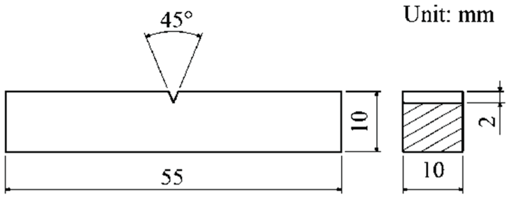
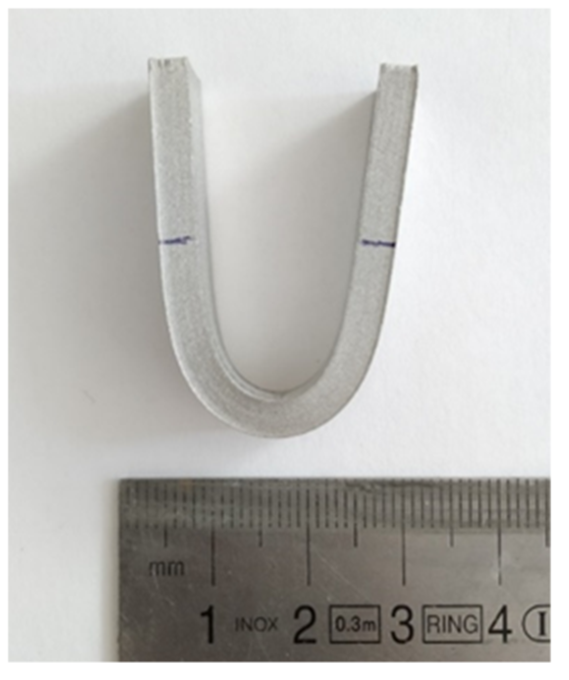
2.3.4. Three-Point Bending Test

According to ASTM F3122-14, ISO 7438:2020 [33] includes plastic deformation methods to evaluate a material’s bending strength and limit of elasticity under bending conditions. These standards are also applicable to metal-based additive-manufactured parts. Three-point bending tests (five samples) were performed using a Galdabini testing machine with a 50 kN load cell. The bending tests were conducted with two supports spaced 42 mm away from the center. The rate of displacement was set to 0.8 mm/s, as indicated in the standard. The procedure was performed until the physical bending limit of each specimen was reached. This physical limit is strictly related to the selected clamping system and the distance between the supports. This configuration produced U-shaped specimens, as depicted in Figure 2.

2.3.5. Rockwell Hardness

ASTM F3122-14 specifies ISO 6508-1:2016 [34] as a standard for the Rockwell hardness (HRB) of additive-manufactured parts. A cubic sample was sectioned along the growth direction; on the internal section of the sample, a 3 × 3 line grid was drawn, following the instructions of ISO 6508-1. The procedure was repeated for three different samples to obtain 27 uniformly spaced indentations by means of an A-200 Galileo hardness tester.

2.3.6. Vickers Hardness

The same procedure followed for the Rockwell tests was used for the Vickers hardness tests, as specified in ISO 6507-1:2018 [35], according to ASTM F3122-14. The indentations were performed using a microhardness tester UHL–VHMT.

3. Results and Discussion
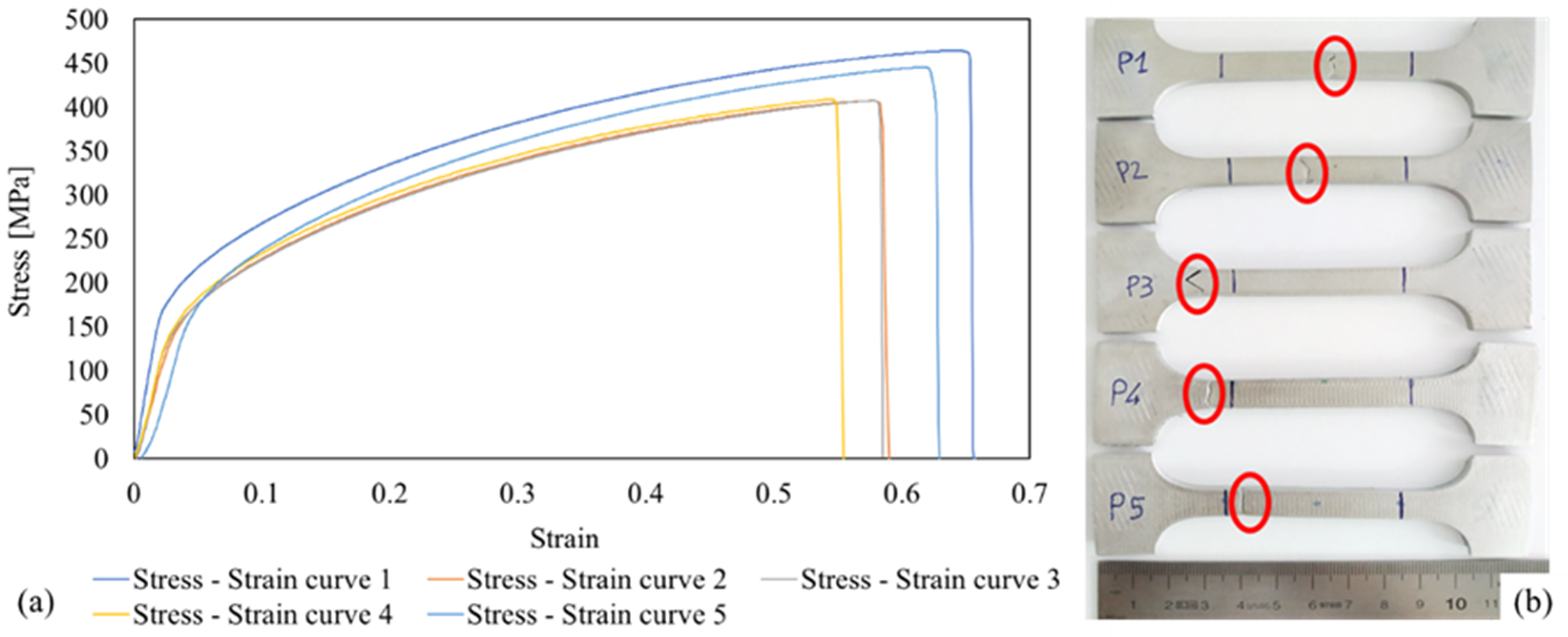
3.1. Tensile Stress

The tensile properties of the specimens, such as the yield strength (σf02), UTS, and elongation at break, are presented in Table 2. The results of the tests indicated that the ME samples exhibited poorer mechanical properties than those of the samples made of monolithic AISI 316 L. Specifically, the average value of the yield strength (141.9 ± 14.1 MPa) was lower by 17% compared to that of the monolithic material. The average value of UTS (426.6 ± 23.7 MPa) was lower than that of the monolithic material by approximately 12%. These results could be attributed to the larger equiaxed grains and full austenitic structure after the sintering phase [16,21]. Regarding the elongation at break, the percentage values were close to those of the monolithic AISI 316L. The inherent porosity of the sample generated by this AM technique [29], particularly the open one, could deteriorate the ductility of the ME specimens owing to local stress concentrations.
To provide a wider context of the tensile properties of stainless steel 316L samples realized with ME, a comparison among tensile values collected in different works is reported in Table 3. On average, the obtained yield and tensile strength resulted slightly lower than the other values presented; conversely, the ductility set the highest level compared to the values available in literature.
The tensile curves, represented in Figure 3a, show a similar trend, demonstrating the repeatability of the printing process. However, the difference in UTS and elongation at break among the samples suggests a significant presence of defects (voids and residual stress as a result of thermal processes). No significant necking phenomenon was observed during the tests.
Figure 3b depicts the failure modes of the specimens. Three samples exhibited fractures inside the useful length, indicated by two blue lines near the edge of the samples. In contrast, samples 3 and 4 show fractures near the filet radius, which is a critical stress intensity zone.

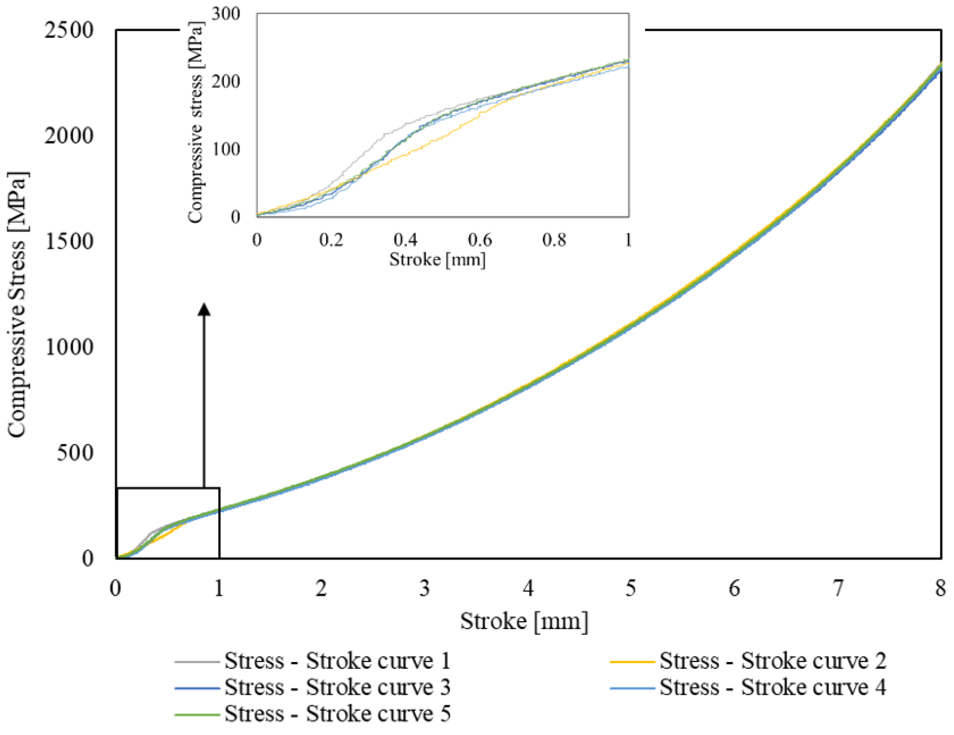
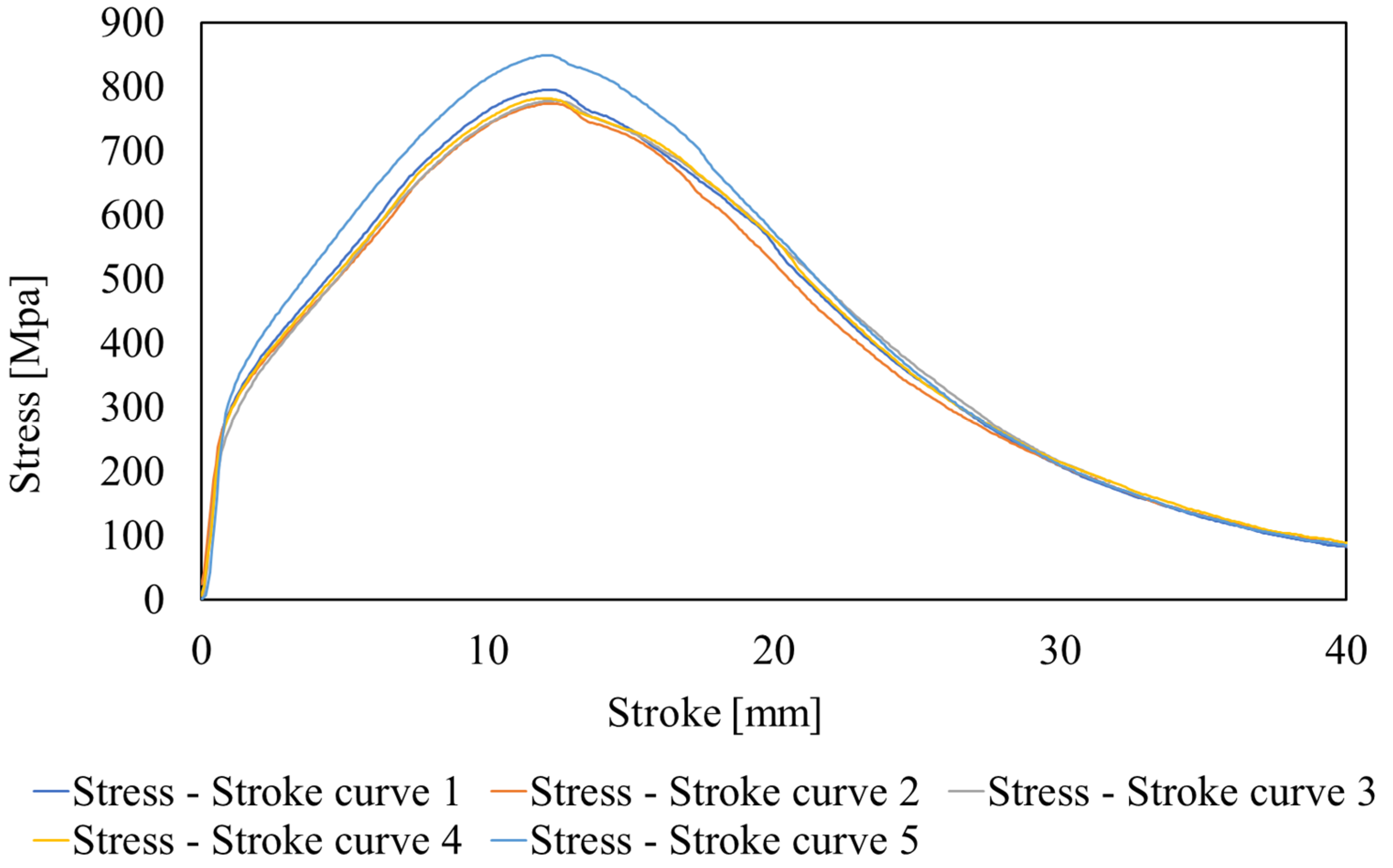
3.2. Compression Stress

The stress–stroke graphs of the compression tests are shown in Figure 4. The near-perfect overlap of the compressive curves proves the stability and repeatability of the tests. In general, for monolithic materials, the absolute values of the tensile and compressive stresses are almost symmetric with respect to the yielding behavior of metals. This condition is also present for ME 316L specimens as the compressive and tensile yield strength values were approximately 150 MPa.
In addition, the compression load seems to guarantee an improvement in the compressive stress values of the samples. The average compressive stress of the ME 316L specimens was 54% lower than that of the tested bulk sample at 1 mm stroke, whereas the average compressive stress value exhibited a deviation of 26% from the value of the bulk specimen at 8 mm stroke.

3.3. Flexural Strength

The three-point bending stress–stroke curves are plotted in Figure 5. Bending tests produce tensile stress on the convex side of the specimens above the neutral axis and compressive stress on the concave side of the specimens below the neutral axis. Flexural strength is the maximum stress in the outermost fiber. The average value of the flexural strength was 795 ± 27 MPa, and the average value of the flexural strain was approximately 44%, with a standard deviation of 1.4. The flexural strength values depend on the type of tests performed and the structural characteristics of the samples printed using the ME technique. During the bending test, the maximum stress was mainly concentrated in a small region above the neutral axis. The metal ME process and further thermal treatments generate an intrinsic percentage of porosity in the specimens, which are highly sensitive to the defect content. Because the gauge area of the samples is limited, for example, compared to the gauge area of tensile specimens, the statistical probability of finding open and closed porosities in the samples is small.
Furthermore, the bending curves show a similar trend, confirming the repeatability of the process, and all the maximum stress values were registered at approximately 12 mm of deflection of the specimens under bending load. All the samples exhibited a complete deformation without the presence of cracks in the area subjected to tensile loading.

3.4. Absorbed Energy
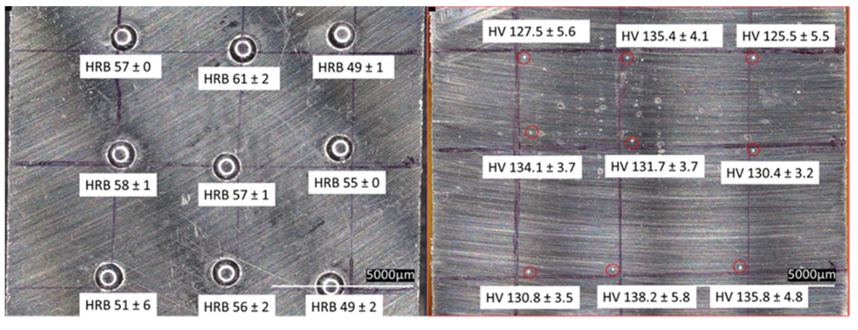
The absorbed energy values of the V-notched specimens are presented in Table 4. The average value (54.6 J ± 8.01) is almost half that of AISI 316L, suggesting the brittleness of the metal specimens printed using the ME technique.
Additionally, samples 2 and 5 underwent a complete fracture (Figure 6a), whereas the other specimens exhibited a partial fracture (Figure 6b).
The brittleness of the metal ME samples can be attributed to two main causes. As reported in [29], 5% of porosity could reduce the ductility of the samples. Moreover, the X-ray diffraction (XRD) analysis (Figure 7) indicated the presence of austenite and δ-ferrite phases. The portion of austenite represents a metallurgical characteristic of the material because AISI 316L is an austenitic stainless steel that is composed of a single stable austenitic phase at 20 °C, owing to the presence of nickel. In contrast, the existence of the δ-ferrite phase is merely an effect of the thermal history of the samples produced by the ME process and subsequent sintering. The formation of the δ-ferrite phase occurred immediately below 1400 °C. The temperature during the extrusion process reached close to 240 °C, whereas that during the sintering cycle reached close to the temperature window of stable delta ferrite and was compatible with its formation.
During the cooling process, the primary δ-ferrite solidifies within the metal matrix, and the transformation of δ to γ ferrite may occur. Because this transformation is a diffusion-controlled process, the fast cooling rate in the sintering cycle (uncontrolled cooling from 1380 °C to room temperature) does not guarantee a sufficiently long time for the completion of the transformation [40]; thus, exceeding portions of δ-ferrite may be retained in the austenitic matrix of specimens at room temperature. The non-equilibrium cooling phase results in the retention of δ-ferrite at the subgrain boundaries [41]. This phenomenon may significantly decrease the strength and ductility and increase the stiffness of the metal ME samples.

3.5. Hardness

Figure 8 depicts values of Rockwell B and Vickers hardness, respectively, depending on their positions on the drawn grid. The average Rockwell B hardness value was approximately 55 ± 4 HRB, which is lower than that of the monolithic AISI 316L (80 HRB [39]), with a deviation of 32%. Regarding the Vickers hardness, the average value (132.2 ± 3.8 HV) was approximately 15% lower with respect to the value of the monolithic AISI 316L (155 HV [39]).
It is reasonable to assume that the difference between the percentage deviations (32% vs. 15%) depends on the correlation between the sample porosity and test methodologies. The Vickers hardness test concentrates the stress on the surface of the specimen, with a limited influence on thickness, leaving a shallow indentation with reduced dimensions, compared to the indentation made during the Rockwell hardness test. Consequently, the Rockwell hardness test is more affected by the presence of porosities, even if they are not outcropped on the surface, as the larger size of the indenter and the greater load applied lead to a greater probability of intercepting non-emerging porosities compared to the probability of finding porosities in the indentations of the Vickers hardness test.
Furthermore, the uniform distribution of the hardness values, both Rockwell B and Vickers, along the growth direction may suggest the homogeneity of the material.

4. Conclusions

This study presents an overview of the main mechanical characterization tests performed on debinded and sintered samples fabricated by means of an innovative metal-polymer feedstock on a low-cost ME machine. Specimens for mechanical characterization were printed using the optimal combination of process parameters for obtaining the highest bulk density compared with that of the monolithic material.
Tensile specimens printed via the ME technique exhibited lower values of yield strength and UTS compared to those of the monolithic material. In particular, the yielding behavior exhibited the worst load values. The compression action on the specimens enhanced the average stress value in direct proportion to the increase in displacement. The bending samples exhibited no cracks or deformations on the surface subjected to a tension load. An XRD analysis showed the abnormal presence of δ-ferrite in the austenitic matrix, which may explain the brittleness of the metal specimens observed during the Charpy impact tests. Both Rockwell B and Vickers hardness tests verified the homogeneous behavior of the material along the growth direction of the layers. In general, the conducted experiments indicated that the ME 316L samples had poorer mechanical performances compared to those of monolithic materials. However, all the tests performed demonstrated the excellent repeatability of this AM process.
Metal extrusion is a prospective cost-effective technique that avoids powder handling and reduces the carbon footprint compared to traditional metal additive manufacturing technologies. Despite the promising advantages, the considerable presence of porosity and the necessary improvement of the mechanical properties narrow the industrial applications of this technique to non-critical metallic parts with high added value, including tanks for dyeing machines and pipelines for the chemical industry due to the high resistance to corrosion. The biocompatibility of the material ensures its use for food and medical applications, and the possibility of producing complex-shaped parts extends its application to heat exchangers and heat sinks.

Author Contributions

Conceptualization M.C., M.Q., G.D.; methodology, M.C., M.Q., G.D.; formal analysis M.C., M.Q.; data curation, M.C., M.Q.; writing—original draft preparation M.C., M.Q.; writing—review and editing, M.C., M.Q., G.D., C.G.; supervision, G.D., C.G., G.M. All authors have read and agreed to the published version of the manuscript.

Funding

This research received no external funding.

Institutional Review Board Statement

Not applicable.

Data Availability Statement

The data presented in this study are available on request from the corresponding author.

Acknowledgments

This paper is part of a research activity carried out within a Ph.D. fellowship titled “Development of innovative powders, also from waste and/or recycled materials, to be used in the production of components using additive technologies” and is funded by ENEA (the Italian National Agency for New Technologies, Energy and Sustainable Economic Development) in collaboration with Region Lombardy.

Conflicts of Interest

The authors declare no conflict of interest.

References

  1. ISO/ASTM 52900:2017; Additive Manufacturing—General Principles—Terminology; ASTM International: West Conshonhocken, PA, USA, 2017.
  2. Enemuoh, E.U.; Duginski, S.; Feyen, C.; Menta, V.G. Effect of process parameters on energy consumption, physical, and mechanical properties of fused deposition modeling. Polymers 2021, 13, 2406. [Google Scholar] [CrossRef]
  3. Özen, A.; Auhl, D.; Völlmecke, C.; Kiendl, J.; Abali, B.E. Optimization of manufacturing parameters and tensile specimen geometry for fused deposition modeling (Fdm) 3d-printed petg. Materials 2021, 14, 2556. [Google Scholar] [CrossRef] [PubMed]
  4. Chalgham, A.; Ehrmann, A.; Wickenkamp, I. Mechanical properties of fdm printed pla parts before and after thermal treatment. Polymers 2021, 13, 1239. [Google Scholar] [CrossRef] [PubMed]
  5. Syrlybayev, D.; Zharylkassyn, B.; Seisekulova, A.; Akhmetov, M.; Perveen, A.; Talamona, D. Optimisation of strength properties of FDM printed parts—A critical review. Polymers 2021, 13, 1587. [Google Scholar] [CrossRef] [PubMed]
  6. Brischetto, S.; Torre, R. Tensile and compressive behavior in the experimental tests for pla specimens produced via fused deposition modelling technique. J. Compos. Sci. 2020, 4, 140. [Google Scholar] [CrossRef]
  7. Agarwal, K.; Kuchipudi, S.K.; Girard, B.; Houser, M. Mechanical properties of fiber reinforced polymer composites: A comparative study of conventional and additive manufacturing methods. J. Compos. Mater. 2018, 52, 3173–3181. [Google Scholar] [CrossRef]
  8. Van Der Klift, F.; Koga, Y.; Todoroki, A.; Ueda, M.; Hirano, Y.; Matsuzaki, R. 3D Printing of Continuous Carbon Fibre Reinforced Thermo-Plastic (CFRTP) Tensile Test Specimens. Open J. Compos. Mater. 2016, 6, 18–27. [Google Scholar] [CrossRef] [Green Version]
  9. Hwang, S.; Reyes, E.I.; Moon, K.S.; Rumpf, R.C.; Kim, N.S. Thermo-mechanical Characterization of Metal/Polymer Composite Filaments and Printing Parameter Study for Fused Deposition Modeling in the 3D Printing Process. J. Electron. Mater. 2015, 44, 771–777. [Google Scholar] [CrossRef]
  10. Ryder, M.A.; Lados, D.A.; Iannacchione, G.S.; Peterson, A.M. Fabrication and properties of novel polymer-metal composites using fused deposition modeling. Compos. Sci. Technol. 2018, 158, 43–50. [Google Scholar] [CrossRef]
  11. Masood, S.H.; Song, W.Q. Development of new metal/polymer materials for rapid tooling using Fused deposition modelling. Mater. Des. 2004, 25, 587–594. [Google Scholar] [CrossRef]
  12. Napibour, M.; Akhoundi, B.; Saed, A.B. Manufacturing of polymer/metal composites by fused deposition modeling process with polyethylene. J. Appl. Polym. Sci. 2019, 137, 48717. [Google Scholar] [CrossRef]
  13. Butt, J.; Oxford, P.; Sadeghi-Esfahlani, S.; Ghorabian, M.; Shirvani, H. Hybrid Manufacturing and Mechanical Characterization of Cu/PLA Composites. Arab. J. Sci. Eng. 2020, 45, 9339–9356. [Google Scholar] [CrossRef]
  14. Fafenrot, S.; Grimmelsmann, N.; Wortmann, M.; Ehrmann, A. Three-dimensional (3D) printing of polymer-metal hybrid materials by fused deposition modeling. Materials 2017, 10, 1199. [Google Scholar] [CrossRef] [PubMed] [Green Version]
  15. Gonzalez-Gutierrez, J.; Godec, D.; Kukla, C.; Schlauf, T.; Burkhardt, C.; Holzer, C. Shaping, Debinding and Sintering of Steel Components Via Fused Filament Fabrication. In Proceedings of the 16th International Scientific Conference on Production Engineering—Computer Integrated Manufacturing and High Speed Machinin, Zadar, Croatia, 8–10 June 2017. [Google Scholar]
  16. Oliveira, R.V.B.; Soldi, V.; Fredel, M.C.; Pires, A.T.N. Ceramic injection moulding: Influence of specimen dimensions and temperature on solvent debinding kinetics. J. Mater. Process. Technol. 2005, 160, 213–220. [Google Scholar] [CrossRef]
  17. Gonzlez-Gutirrez, J.; Beulke, G.; Emri, I. Powder Injection Molding of Metal and Ceramic Parts. In Some Critical Issues for Injection Molding; Intechopen: London, UK, 2012. [Google Scholar] [CrossRef] [Green Version]
  18. Liu, B.; Wang, Y.; Lin, Z.; Zhang, T. Creating metal parts by Fused Deposition Modeling and Sintering. Mater. Lett. 2020, 263, 127252. [Google Scholar] [CrossRef]
  19. Gong, H.; Crater, C.; Ordonez, A.; Ward, C.; Waller, M.; Ginn, C. Material Properties and Shrinkage of 3D Printing Parts using Ultrafuse Stainless Steel 316LX Filament. MATEC Web Conf. 2018, 249, 1–5. [Google Scholar] [CrossRef]
  20. Damon, J.; Dietrich, S.; Gorantla, S.; Popp, U.; Okolo, B.; Schulze, V. Process porosity and mechanical performance of fused filament fabricated 316L stainless steel. Rapid Prototyp. J. 2019, 25, 1319–1327. [Google Scholar] [CrossRef]
  21. Kurose, T.; Abe, Y.; Santos, M.V.A.; Kanaya, Y.; Ishigami, A.; Tanaka, S.; Ito, H. Influence of the Layer Directions on the Properties of 316L Stainless Steel Parts Fabricated through Fused Deposition of Metals. Materials 2020, 13, 2493. [Google Scholar] [CrossRef]
  22. Henry, T.C.; Morales, M.A.; Cole, D.P.; Shumeyko, C.M.; Riddick, J.C. Mechanical behavior of 17-4 PH stainless steel processed by atomic diffusion additive manufacturing. Int. J. Adv. Manuf. Technol. 2021, 114, 2103–2114. [Google Scholar] [CrossRef]
  23. Gong, H.; Snelling, D.; Kardel, K.; Carrano, A. Comparison of Stainless Steel 316L Parts Made by FDM- and SLM-Based Additive Manufacturing Processes. JOM 2019, 71, 880–885. [Google Scholar] [CrossRef]
  24. Gonzalez-Gutierrez, J.; Arbeiter, F.; Schlauf, T.; Kukla, C.; Holzer, C. Tensile properties of sintered 17-4PH stainless steel fabricated by material extrusion additive manufacturing. Mater. Lett. 2019, 248, 165–168. [Google Scholar] [CrossRef]
  25. Gratton, A. Comparison of Mechanical, Metallurgical Properties of 17-4PH Stainless Steel between Direct Metal Laser Sintering (DMLS) and Traditional Manufacturing Methods. Proc. Natl. Conf. Undergrad. Res. 2012, 2012, 423–431. [Google Scholar]
  26. Liu, L.; Zheng, H.X.; Zeng, T.X.; Song, K.; Xu, X.Y.; Chen, B. Microstructure evolution and wear behaviour of VN strengthened 17-4PH stainless steel fabricated by metal injection molding. Philos. Mag. 2021, 101, 2108–2122. [Google Scholar] [CrossRef]
  27. Abe, Y.; Kurose, T.; Santos, M.V.A.; Kanaya, Y.; Ishigami, A.; Tanaka, S.; Ito, H. Effect of layer directions on internal structures and tensile properties of 17-4ph stainless steel parts fabricated by fused deposition of metals. Materials 2021, 14, 243. [Google Scholar] [CrossRef] [PubMed]
  28. ASTM F3122-14; Standard Guide for Evaluating Mechanical Properties of Metal Materials Made via Additive Manufacturing Processes; ASTM International: West Conshonhocken, PA, USA, 2014.
  29. Quarto, M.; Carminati, M.; D’Urso, G. Density and shrinkage evaluation of AISI 316L parts printed via FDM process. Mater. Manuf. Process. 2021, 36, 1–9. [Google Scholar] [CrossRef]
  30. ISO 6892-1:2020; Metallic Materials—Tensile Testing—Part 1: Method of Test at Room Temperature; International Organization for Standardization: Ginerva, Switzerland, 2020.
  31. ASTM E9:2019; Standard Test Methods of Compression Testing of Metallic Materials at Room Temperature; ASTM International: West Conshonhocken, PA, USA, 2019.
  32. ISO 148—1:2016; Metallic materials—Charpy Pendulum Impact test—Part 1: Test Method; International Organization for Standardization: Ginerva, Switzerland, 2016.
  33. ISO 7438:2020; Metallic Materials—Bend Tests; International Organization for Standardization: Ginerva, Switzerland, 2020.
  34. ISO 6508-1:2016; Metallic Materials—Rockwell Hardness Test—Part 1: Test Method; International Organization for Standardization: Ginerva, Switzerland, 2020.
  35. ISO 6507-1:2018; Metallic Materials—Vickers Hardness Test—Part 1: Test Method; International Organization for Standardization: Ginerva, Switzerland, 2020.
  36. ASTM A666-15; Standard Specification for Annealed or Cold-Worked Austenitic Stainless Steel Sheet, Strip, Plate, and Flat Bar; ASTM International: West Conshonhocken, PA, USA, 2014.
  37. Ait-Mansour, I.; Kretzschmar, N.; Chekurov, S.; Salmi, M.; Rech, J. Design-dependent shrinkage compensation modeling and mechanical property targeting of metal FFF. Prog. Addit. Manuf. 2020, 5, 51–57. [Google Scholar] [CrossRef] [Green Version]
  38. Rosnitschek, T.; Tremmel, S.; Seefeldt, A.; Alber-Laukant, B.; Neumeyer, T.; Altstädt, V. Correlations of geometry and infill degree of extrusion additively manufactured 316l stainless steel components. Materials 2021, 14, 5173. [Google Scholar] [CrossRef]
  39. MatWeb. Available online: http://www.matweb.com/search/DataSheet.aspx?MatGUID=a2d0107bf958442e9f8db6dc9933fe31 (accessed on 13 January 2022).
  40. Dadfar, M.; Fathi, M.H.; Karimzadeh, F.; Dadfar, M.R.; Saatchi, A. Effect of TIG welding on corrosion behavior of 316L stainless steel. Mater. Lett. 2007, 61, 2343–2346. [Google Scholar] [CrossRef]
  41. Ziętala, M.; Durejko, T.; Polański, M.; Kunce, I.; Płociński, T.; Zieliński, W.; Łazińska, M.; Stępniowski, W.; Czujko, T.; Kurzydłowski, K.J.; et al. The microstructure, mechanical properties and corrosion resistance of 316 L stainless steel fabricated using laser engineered net shaping. Mater. Sci. Eng. A 2016, 677, 1–10. [Google Scholar] [CrossRef]
Figure 1. Dimensions of Charpy impact samples.
Applsci 12 01433 g001
Figure 2. U-bend sample.
Applsci 12 01433 g002
Figure 3. Tensile stress–strain curves (a); fracture positions of the samples (b).
Applsci 12 01433 g003
Figure 4. Compressive stress–stroke curves.
Applsci 12 01433 g004
Figure 5. Bending stress–stroke curves.
Applsci 12 01433 g005
Figure 6. Samples with complete fracture (a), samples with partial fracture (b).
Applsci 12 01433 g006
Figure 7. XRD patterns of the ME 316L stainless steel.
Applsci 12 01433 g007
Figure 8. Rockwell B Hardness (left) and Vickers hardness (right) values in their relative positions within the sample.
Applsci 12 01433 g008
Table 1. Optimized process parameters combination.
Nozzle TemperatureInfill TypePrinting SpeedLayer ThicknessInfill DensityBuild Orientation
170 °C Applsci 12 01433 i00120 mm/s0.1 mm 100%Flat
Table 2. Tensile properties of 316L AM samples.
σf02 (MPa)UTS (MPa)Elongation at Break (%)
Sample 1161.3464.141%
Sample 2125.0407.337%
Sample 3134.6405.932%
Sample 4132.9409.032%
Sample 5155.7445.238%
AISI 316L [36]17048560%
Table 3. Comparison of tensile properties among 316L specimens fabricated by means of the ME technique.
Sourceσf02 (MPa)UTS (MPa)Elongation at Break (%)
This work141.9 ± 14.1426.6 ± 23.736.4 ± 3.15
Ait-Mansour et al. [37]140.77 ± 6.97311.81 ± 39.9612.48 ± 2.81
Gong et al. [23]16746531
Liu et al. [18]194 ± 19441 ± 2729.5 ± 3.8
Rosnitschek et al. [38]-296 ± 7832 ± 16
Damon et al. [20]155 50032
AISI 316L [36]17048560
Table 4. Absorbed energy values of samples.
Absorbed Energy (J)
Sample 162.5
Sample 258.5
Sample 342.0
Sample 448.5
Sample 561.5
Monolithic AISI316L103 [39]
Publisher’s Note: MDPI stays neutral with regard to jurisdictional claims in published maps and institutional affiliations.

