Communication

Diffraction Effects of IEC63034 Standard Micro-Baffle on the Frequency Response Measurements of Microspeakers

Key Laboratory of Modern Acoustics, Institute of Acoustics, Nanjing University, Nanjing 210093, China
*
Authors to whom correspondence should be addressed.
Appl. Sci. 2022, 12(3), 1420; https://doi.org/10.3390/app12031420
Submission received: 16 December 2021 / Revised: 16 January 2022 / Accepted: 25 January 2022 / Published: 28 January 2022

Abstract

:
This study investigates the diffraction effects of the IEC 63034 standard micro–baffle (SMB) on the frequency response (FR) measurements of microspeakers based on the extended Biot–Tolstoy–Medwin technique. Two different cases with and without the consideration of the backward diffractions of the SMB were investigated, which correspond to different practical measurement conditions of microspeaker drivers and closed-box microspeaker modules. The experimental results obtained were consistent with the theoretical analysis and numerical calculations. Normalized FR curves characterizing the SMB diffraction effects were presented, which can be used to compensate the FRs measured on the SMB to obtain the results measured on an ideal infinite baffle and eliminate the SMB diffraction effects.

1. Introduction

Frequency response (FR) is a key evaluation criterion for the performance of a microspeaker. Obtaining the FR accurately is of great importance in microspeaker design and practical applications. To measure the FR correctly, finite-size baffles are usually used to shield the front-side radiation of a microspeaker from the effect of the rear-side radiation. Finite-size baffles can significantly influence the FRs of electroacoustic transducers owing to edge diffractions. To obtain the FR of a microspeaker precisely from baffle measurements, the diffraction effects of the measuring baffle should be known beforehand. To standardize the measurement condition for microspeaker industry, the International Electrotechnical Commission (IEC) has specified a standard micro-baffle (SMB) for microspeaker measurements [1], but no further information about the diffraction effects of the SMB has been provided. Therefore, it will be of great instructive value to quantitatively evaluate the SMB diffraction effects for the microspeaker industry.
Several approaches have been established to investigate the edge diffraction problem [2], such as the Kirchhoff diffraction approximation [3,4], geometrical theory of diffraction (GTD) [5,6,7], Hadden–Pierce solution [8,9], and Biot–Tolstoy–Medwin (BTM) technique [10,11,12]. In the electroacoustic domain, the diffraction effects of the edges of loudspeaker cabinets or measuring baffles have been discussed for decades based on these analytical solutions [13,14]. The BTM technique is of particular interest because it can be digitalized by a time-sampling technique and applied to first- and higher-order diffractions [15,16]. The BTM technique is a time-domain solution for edge diffraction originating from the work by Biot and Tolstoy in 1957, where a closed-form impulse response solution for an infinite rigid wedge was presented [10]. Medwin et al. extended it to the diffraction problem of finite wedges with a concept of “discrete Huygens interpretation” by placing a series of secondary sources along the ridge of the wedge [12]. Based on Medwin’s work, Svensson et al. improved the BTM technique by deriving analytical directivity functions for the secondary sources and obtained more accurate solutions [17].
In this study, the SMB diffraction effects on the FRs of microspeakers were investigated based on the extended BTM technique. Two different cases with and without the consideration of the backward diffraction of the SMB were studied, which correspond to the different measurement conditions of microspeaker drivers and closed-box microspeaker modules. Experiments were conducted and showed validity. Based on the theoretical analysis and numerical calculations, normalized FR curves characterizing the SMB diffraction effects on the FR measurements of microspeakers are presented. With the normalized FR curves, one can compensate the FR of a microspeaker measured on the SMB to obtain the results measured on an ideal infinite baffle, and eliminate the diffraction effects caused by the SMB.

2. Theoretical Analysis

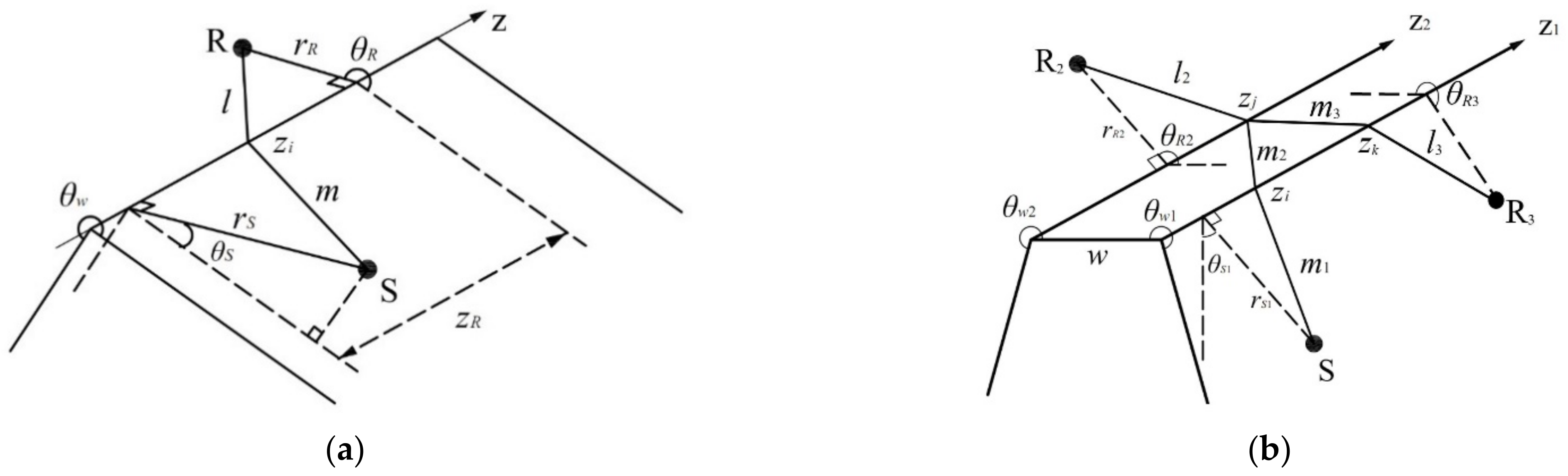
2.1. Extended BTM Technique

The extended BTM technique is fully described by Svenssonet al. in [17]. For the diffraction problem of an infinite wedge with geometry as described in Figure 1a, where a point source S with a source signal q ( t ) = ρ 0 A ( t ) / 4 π is located at ( r S ,   θ S , 0) and a receiver R is at ( r R ,   θ R ,   z R ) in the cylindrical coordinate system, an explicit solution for the diffracted sound pressure received at position R can be written as [17]:
p d i f f r ( t ) = q t m ( z ) + l ( z ) c · D ( m ( z ) ,   l ( z ) ,   θ S ,   θ R ) m ( z ) l ( z ) d z
where D ( m ( z ) ,   l ( z ) ,   θ S ,   θ R ) is the directivity function with
D ( m ( z ) ,   l ( z ) ,   θ S ,   θ R ) = v β ( m ( z ) ,   l ( z ) ,   θ S ,   θ R ) 4 π
β ( τ ) = β + + ( τ ) + β + ( τ ) + β + ( τ ) + β ( τ )
β ± ± ( τ ) = sin v π ± θ S ± θ R cosh v η ( τ ) cos v π ± θ S ± θ R
η ( τ ) = cosh 1 c 2 τ 2 ( r S 2 + r R 2 + z R 2 ) 2 r S r R
where v = π / θ w is the wedge index; τ   = m ( z ) + l ( z ) / c . c is the speed of sound. For finite-wedge cases, the limits of the integral in Equation (1) are replaced by the two endpoints of the wedge.
The integral in Equation (1) can be considered as a convolution integral of the source signal q(t) with an impulse response describing the diffraction effect of the wedge. It is convenient to divide the edges into equally sized elements of size Δz for numerical implementation, and the contribution of each element to the total impulse response can be expressed as [17]:
Δ h i v 4 π β ( m ( z ) ,   l ( z ) ,   θ S ,   θ R ) m ( z ) l ( z ) Δ z i
The solution described by Equations (1)–(6) can be extended to the application of higher-order diffractions. Considering a truncated wedge with two parallel edges, as depicted in Figure 1b, R2 and R3 are the receivers of the second- and third-order diffractions, respectively. Treating each element on edge z1 as a secondary source for edge z2, the second-order diffraction contributions of the propagation path between S and R2 can be derived as [16]:
Δ h ij v 1 v 2 ( 4 π ) 2 β ( m 1 ( z i ) ,   m 2 ( z i ,   z j ) ,   θ S 1 ,   θ R 1 ) β ( m 2 ( z i ,   z j ) ,   l 2 ( z j ) ,   θ S 2 ,   θ R 2 ) 2 m 1 ( z i ) ,   m 2 ( z i ,   z j ) l 2 ( z j ) Δ z i Δ z j
where the factor of 2 in the denominator compensates for the doubling in pressure generated by an acoustic source when mounted on a baffle [17]. The third-order diffraction contributions of the propagation path between S and R3 can be derived similarly as follows [16]:
Δ h i j k v 1 v 2 v 3 ( 4 π ) 3 β ( m 1 ( z i ) ,   m 2 ( z i ,   z j ) ,   θ S 1 ,   θ R 1 ) β ( m 2 ( z i ,   z j ) , m 3 ( z j ,   z k ) ,   θ S 2 ,   θ R 2 ) β ( m 3 ( z j ,   z k ) ,   l 3 ( z k ) ,   θ S 3 ,   θ R 3 ) 2 m 1 ( z i ) ,   m 2 ( z i ,   z j ) 2 m 3 ( z j ,   z k ) l 3 ( z k ) Δ z i Δ z j Δ z k

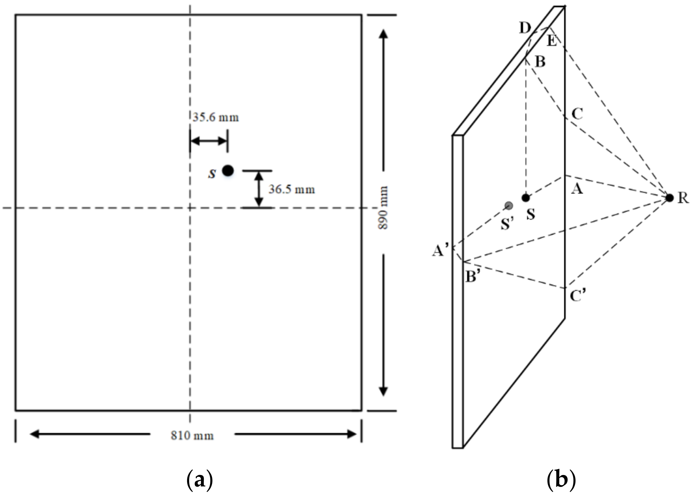
2.2. Diffractive Analysis of the SMB

To comprehensively analyze the diffraction effects of a finite-size baffle, two different cases should be considered. When a microspeaker driver is measured on a baffle, the sound radiated on the front side and rear side of the microspeaker can be regarded as two separate sources vibrating simultaneously with the same amplitude, but opposite phases. Under these circumstances, diffractions caused by sources on both sides should be considered. When a closed-box microspeaker module is measured on the baffle, only the diffractions caused by the source on the front side should be considered.
Figure 2a shows the SMB dimensions specified in IEC 63034 [1]. During the measurement process, the microspeaker is specified to be installed at the position (35.6 mm, 36.5 mm), and the microphone shall be placed directly in front of the microspeaker with a measuring distance of 0.1 m. Notably, diffractions up to the third order were considered in this study which can provide sufficient information about the SMB diffraction effects on the microspeaker FRs. Typical diffracted propagation paths describing the first-, second-, and third-order SMB diffractions are shown in Figure 2b. Considering the diffractions caused by the front-side source S, SAR is the first-order diffraction path, and SBCR and SBDER are the second- and third-order diffraction paths, respectively. Similarly, S’A’B’R and S’A’B’C’R are the second- and third-order diffractions caused by the rear-side source S’.
Based on the extended BTM technique, the impulse response of the diffracted sound can be calculated using Equations (6)–(8) in the time domain. The diffractions in the frequency domain can be obtained by applying fast Fourier transform (FFT) to transform the impulse response to the frequency domain. The total response received at the measuring point is obtained as the superposition of the direct and diffracted sounds. Therefore,
p t o t a l ( ω ) = p d i r e c t ( ω )   + p d i f f _ f   ( ω )   p d i f f _ r ( ω ) ,
where p d i r e c t ( ω ) is the direct sound, and p d i f f _ f   ( ω ) and   p d i f f _ r ( ω ) are the diffracted sounds from the front-side and rear-side sources, respectively. The minus sign in Equation (9) denotes the opposite phase of the source in the rear side. p d i f f _ r ( ω ) is set to zero when a closed-box microspeaker module is considered. To describe the SMB diffraction effects more explicitly, a normalized FR can be built as [15]:
H ( ω ) = p t o t a l ( ω )   /   p d i r e c t ( ω )
which is the transfer function between the total sound and the direct sound, characterizing the degree of influence on the FR of a microspeaker by the SMB diffraction effects.

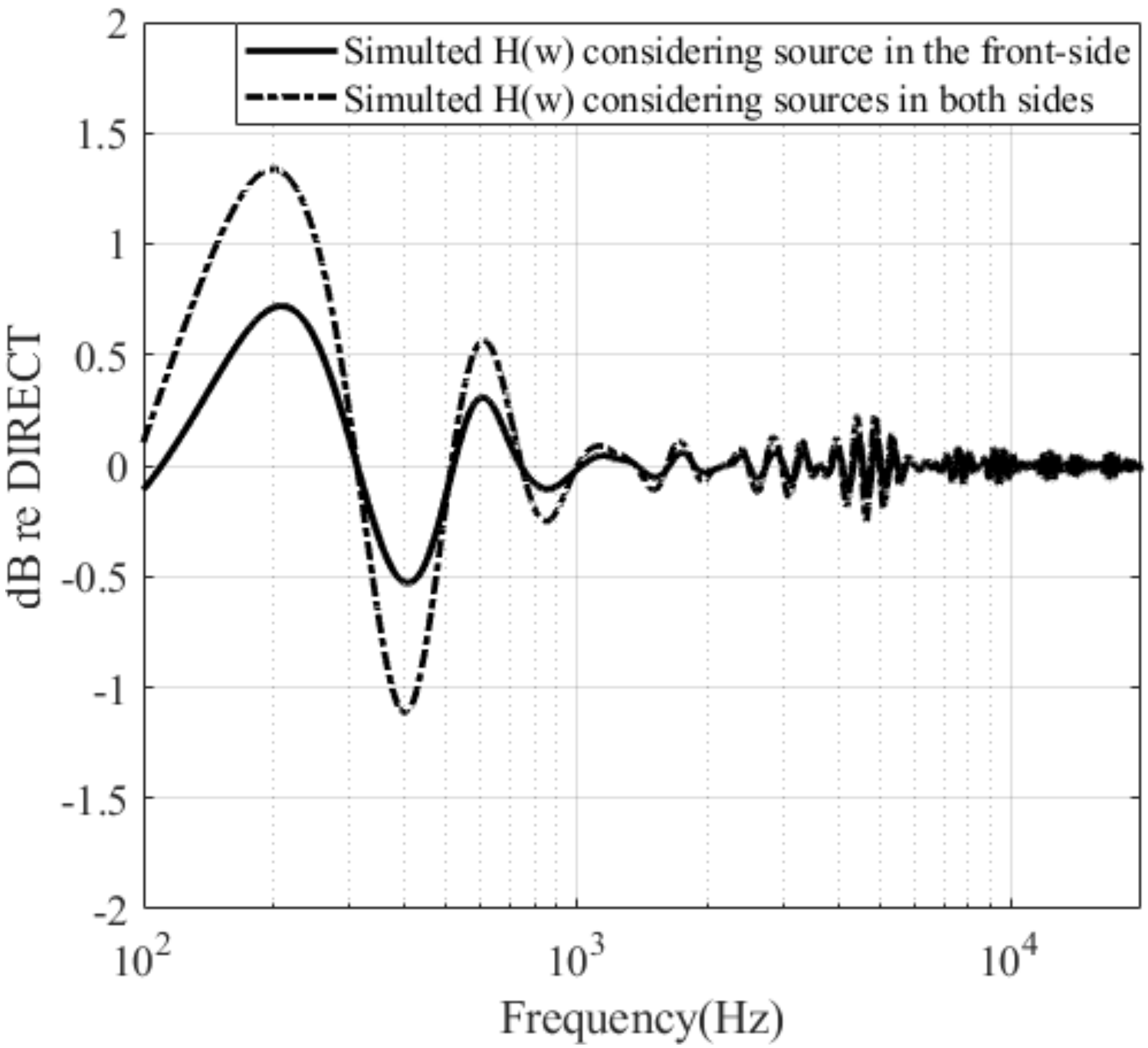
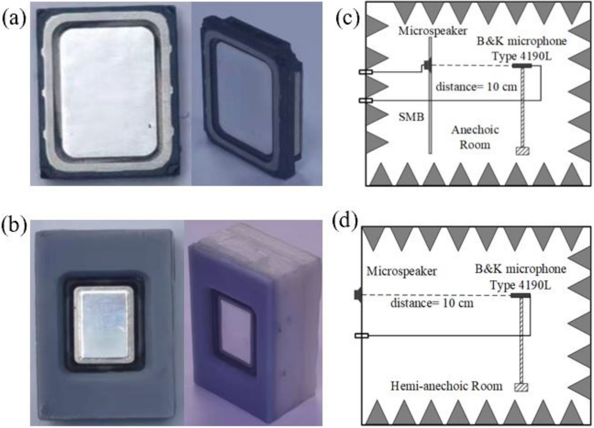
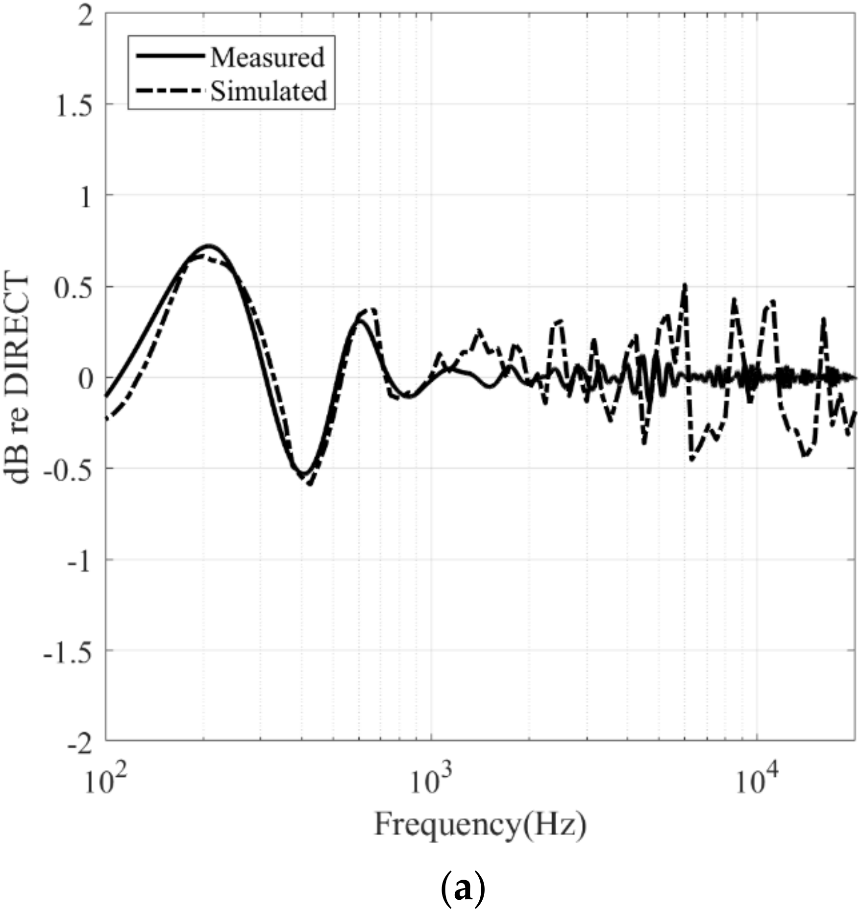
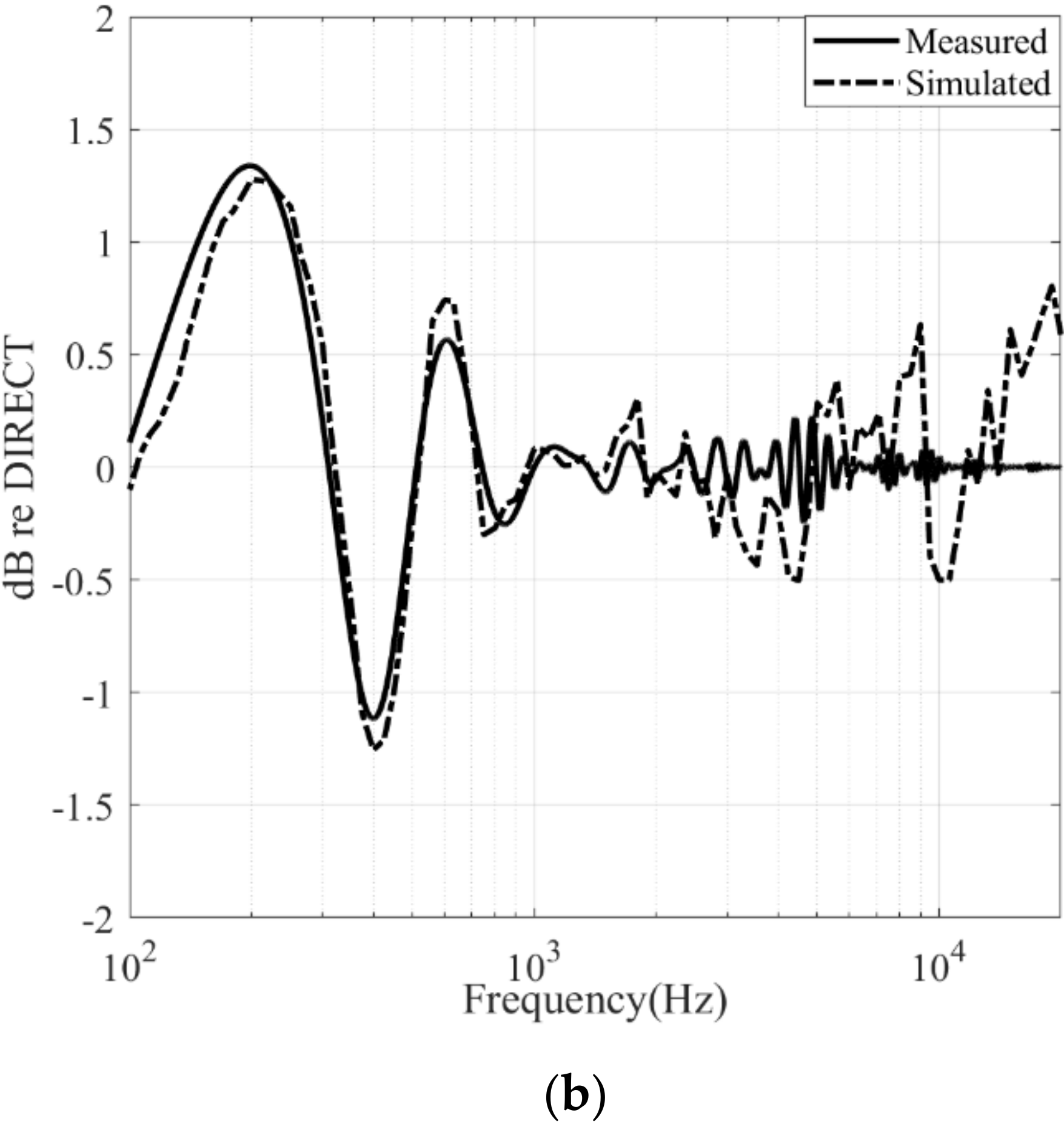
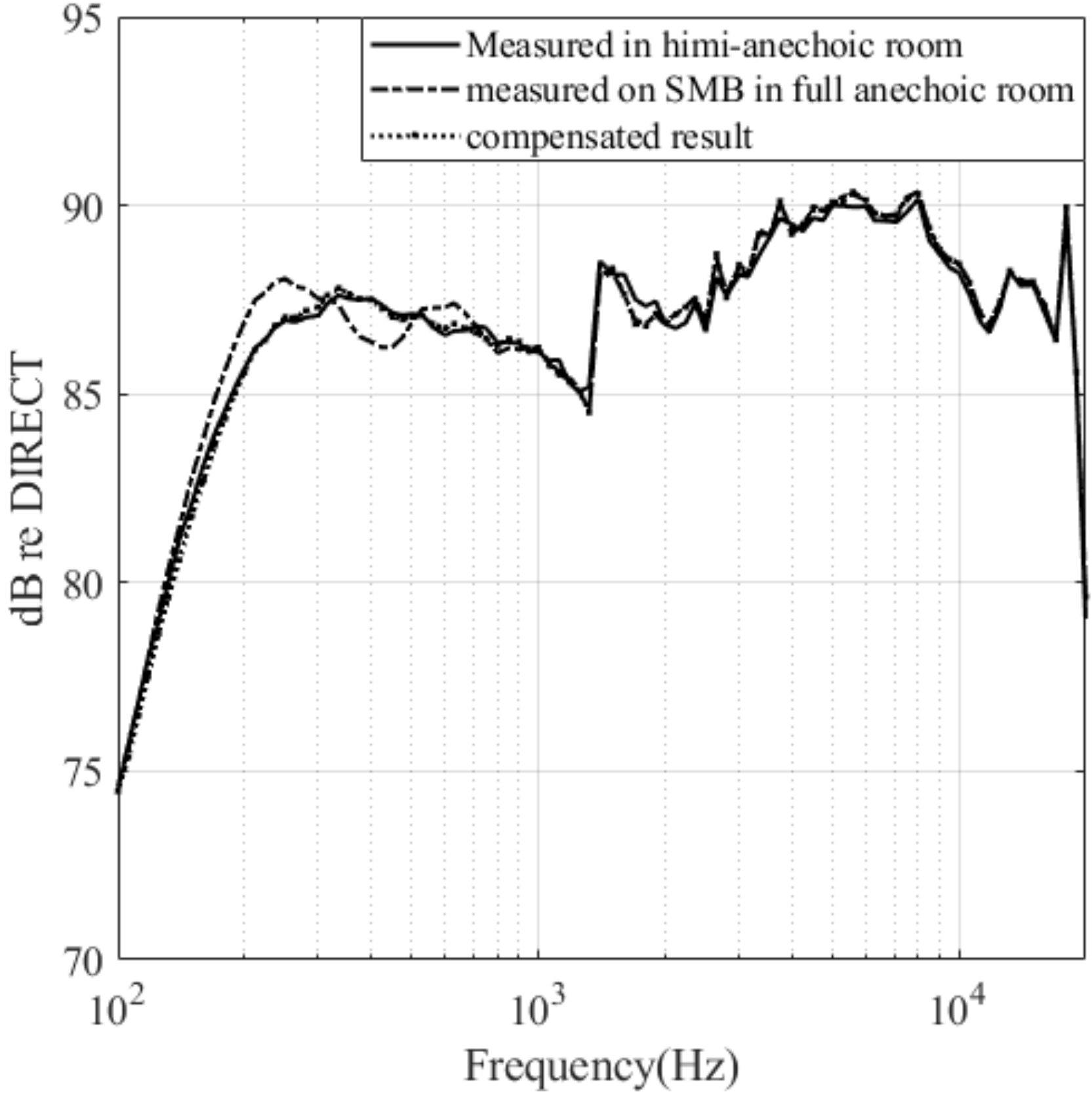
3. Numerical Simulation and Experimental Validation

Numerical simulations were performed to obtain the normalized FR H ( ω ) . During the simulation process, the edges of the SMB were divided into equally sized elements with a size of 1 mm, and a sampling frequency of 100 kHz is adopted. The thickness of the SMB was set to be 10 mm in the simulation. Figure 3 depicts the two normalized FRs simulated with and without the consideration of the diffractions caused by the source on the rear side. This clearly shows that a microspeaker with a flat FR produces an uneven response in the receiver owing to the presence of the SMB. Furthermore, larger fluctuations in the normalized FR curves can be observed when the diffractions caused by the source on the rear side are considered. Relatively large fluctuations exist at frequencies below 1 kHz in both normalized FR curves. Notably, the SMB causes two large peaks at approximately 200 Hz and 600 Hz, as well as a considerable dip at approximately 400 Hz. As the frequency increases, the fluctuation attenuates, which illustrates that higher-frequency waves are more immune to diffraction than lower-frequency waves. Consequently, only diffractions in the low-frequency domain should be considered in practical measurements. Table 1 presents the two normalized FRs in Figure 3 for frequencies between 100 Hz and 1 kHz.
To validate the theoretical analysis and numerical simulations, the normalized FRs H ( ω ) were first measured and thereafter compared to the calculated values. Experiments were performed in the following steps: firstly, the FR of a microspeaker on the SMB was measured in a full anechoic room with size of 11.4 m × 7.8 m × 6.7 m. Secondly, the FR of the microspeaker was obtained in a hemi-anechoic room with size of 6.5 m × 5.5 m× 4 m by mounting the microspeaker on the reflecting surface of the hemi-anechoic room. The difference between the two measured sound pressure levels (SPL) is the measured, normalized FR H ( ω ) . The experimental setup is shown in Figure 4. A microspeaker driver and a closed-box microspeaker module were chosen as the sources, and a reference microphone (type 4190 L, Brüel & Kjær) was placed in front of the microspeakers with a measuring distance of 0.1 m. The size of the microspeaker driver is 11 mm × 15 mm × 3.5 mm and the size of the closed-box microspeaker module is 18 mm × 29 mm × 12 mm. The SMB used in the experiments is made of aluminum with a thickness of 10 mm. The SPL of the microspeakers was obtained using a PULSE Analyzer (type 3160A, Brüel & Kjær). Notably, only the front side of the driver will radiate sound in the hemi-anechoic room when a microspeaker driver is measured in the second step.
The normalized FR measured via the microspeaker driver and a closed-box microspeaker module is shown in Figure 5a,b, respectively. The simulated results are also plotted in the figures for comparison. The degree of agreements between the normalized FR curves at most frequencies were satisfactory, thereby validating the theoretical analysis and numerical simulations. Relatively larger discrepancies exist at higher frequencies, and may have resulted from measurement errors.

4. Discussion

Based on the analysis in the previous section, the normalized FR represents the degree to which the FR of a microspeaker is affected by the diffraction effects of the SMB. From another perspective, the normalized FR can be used to compensate the FRs measured on the SMB to obtain the results measured on an ideal infinite baffle. Therefore, p i d e a l ( ω ) = p SMB ( ω ) / H ( ω ) . Figure 6 depicts the compensation result of the FR of a microspeaker driver measured on the SMB. Clearly, the compensated FR is consistent with that measured in a hemi-anechoic room, which can be considered as the results are measured on an ideal infinite baffle. The SMB diffraction effects are almost completely eliminated by the compensation process.

5. Conclusions

In summary, the diffraction effects of the IEC63034 SMB on the FR measurements of microspeakers were investigated in this study based on the extended BTM technique. Two normalized FRs were presented to describe the SMB diffraction effects and compensate the FRs measured on the SMB to obtain the results measured on an ideal infinite baffle. Based on the numerical simulations and practical measurements, it can be concluded that the SMB would cause relatively large fluctuations on the FR of a microspeaker at frequencies lower than 1 kHz. At higher frequencies, the SMB diffraction effects can be neglected. With the normalized FRs presented in this study, the diffraction effects of the SMB can be eliminated by the compensation process.

Author Contributions

Conceptualization, J.H. and Y.S.; methodology, J.H.; validation, J.H. and J.G.; formal analysis, J.H.; investigation, J.H.; resources, X.F. and Y.S.; writing—original draft preparation, J.H.; writing—review and editing, J.G., X.F. and Y.S.; supervision, X.F. and Y.S.; project administration, X.F. and Y.S. All authors have read and agreed to the published version of the manuscript.

Funding

This work was supported by National Natural Science Foundation of China (Grant No. 11904330).

Conflicts of Interest

The authors declare no conflict of interest.

References

  1. IEC 63034 Ed. 1.0 b:2020; Microspeakers; International Electrotechnical Commission: Geneva, Switzerland, 2020.
  2. Li, K.M.; Wong, H.Y. A review of commonly used analytical and empirical formulae for predicting sound diffracted by a thin screen. Appl. Acoust. 2005, 66, 45–76. [Google Scholar] [CrossRef]
  3. Trorey, A.W. Diffractions for arbitrary source–receiver locations. Geophysics 1977, 42, 1177–1182. [Google Scholar] [CrossRef]
  4. Norton, G.V.; Novarini, J.C.; Keiffer, R.S. An Evaluation of the Kirchhoff Approximation in Predicting the Axial Impulse Response of Hard and Soft Disks. J. Acoust. Soc. Am. 1993, 93, 3049–3056. [Google Scholar] [CrossRef]
  5. Keller, J.B. Diffraction by an aperture. J. Appl. Phys. 1957, 28, 426–444. [Google Scholar] [CrossRef]
  6. Keller, J.B. Diffraction by an aperture II. J. Appl. Phys. 1957, 28, 570–579. [Google Scholar] [CrossRef]
  7. Keller, J.B. Geometrical Theory of Diffraction. J. Opt. Soc. Am. 1962, 52, 116–130. [Google Scholar] [CrossRef] [PubMed]
  8. Pierce, A.D. Diffraction of Sound around Corners and over Wide Barriers. J. Acoust. Soc. Am. 1974, 55, 941–955. [Google Scholar] [CrossRef]
  9. Hadden, W.J.; Pierce, A.D. Sound Diffraction around Screens and Wedges for Arbitrary Point Source Location. J. Acoust. Soc. Am. 1981, 69, 1266–1276. [Google Scholar] [CrossRef]
  10. Biot, M.A.; Tolstoy, I. Formulation of wave propagation in infinite media by normal coordinates with an application to diffraction. J. Acoust. Soc. Am. 1957, 29, 381–391. [Google Scholar] [CrossRef]
  11. Medwin, H. Shadowing by finite noise barriers. J. Acoust. Soc. Am. 1981, 69, 1060–1064. [Google Scholar] [CrossRef]
  12. Medwin, H.; Childs, E.; Jebsen, G.M. Impulse studies of double diffraction: A discrete Huygens interpretation. J. Acoust. Soc. Am. 1982, 72, 1005–1013. [Google Scholar] [CrossRef]
  13. Wright, J.R. Fundamentals of Diffraction. J. Audio Eng. Soc. 1997, 45, 347–356. [Google Scholar]
  14. Vanderkooy, J.A. Simple Theory of Cabinet Edge Diffraction. J. Audio Eng. Soc. 1991, 39, 923–933. [Google Scholar]
  15. Le, Y.; Shen, Y.; Xia, J. A Diffractive Study on the Relation between Finite Baffle and Loudspeaker Measurement. J. Audio Eng. Soc. 2011, 59, 944–952. [Google Scholar]
  16. Le, Y.; Shen, Y.; Xia, J. Calculation of Loudspeaker Cabinet Diffraction and Correction. Chin. Phys. Lett. 2011, 28, 104303. [Google Scholar] [CrossRef]
  17. Svenssen, U.P.; Fred, R.I.; Vanderkooy, J. An Analytic Secondary Source Model of Edge Diffraction Impulse Responses. J. Acoust. Soc. Am. 1999, 106, 2331–2344. [Google Scholar] [CrossRef] [Green Version]
Figure 1. Geometries for describing the BTM technique: (a) infinite wedge with a source and receiver for the first-order diffraction, and (b) truncated wedge with a source and two receivers for the second- and third-order diffractions.
Applsci 12 01420 g001
Figure 2. Dimensions of the SMB and typical diffraction paths. (a) Dimensions of the SMB and (b) typical diffraction paths of the SMB.
Applsci 12 01420 g002
Figure 3. Normalized FR H ( ω ) with and without the consideration of the diffractions caused by the source on the rear side.
Applsci 12 01420 g003
Figure 4. Experimental setup for measuring the normalized FRs. (a) Front and side views of the microspeaker driver and, (b) front and side views of the closed-box microspeaker module. (c) Schematic view of the experimental setup in the anechoic room, and (d) in hemi-anechoic room.
Applsci 12 01420 g004
Figure 5. Comparison of the normalized FRs between the measured and simulated results. (a) Results from the microspeaker driver and (b) results from the closed-box microspeaker module.
Applsci 12 01420 g005aApplsci 12 01420 g005b
Figure 6. Compensation of the SMB diffraction effects by the normalized FR.
Applsci 12 01420 g006
Table 1. Normalized FRs “H(ω)” for center frequencies of the 1/3 oct bands between 100 Hz and 1 kHz.
Frequency (Hz) H ( ω )   Considering   the
Front-Side Source (dB)
H ( ω )   Considering   Sources   on   Both   Sides   ( dB )
100−0.1090.105
1250.1630.638
1600.5091.142
2000.7141.337
2500.5651.109
315−0.036−0.077
400−0.527−1.114
500−0.129−0.157
6300.2860.541
800−0.081−0.198
1000−0.018−0.005
Publisher’s Note: MDPI stays neutral with regard to jurisdictional claims in published maps and institutional affiliations.

