1. Introduction
With the rapid development of cloud based real-time AI, network video services are now available for interactive applications requiring a closed loop response [
1]. Cloud VR and autonomous systems, including drones, vehicles, and robots, can achieve the same level of performance at fraction of the cost through cloud processing. Vehicles that can carry advanced accident detection systems, micro drones navigating through complex forests at high speeds, VR users with light weight googles without suffering dizziness, robots that recover from trips; all these applications require reliable low latency delivery of content to and from the cloud. One critical content component is video.
Different video applications require different video transmission latencies to ensure QOS (quality of service). One-way video transmission applications such as live video and VOD (video on-demand) only require a latency within 2–5 s [
2]. Interactive video applications such as video conference have become more and more popular. The latency of video software such as Zoom is between 300 ms and 1 s [
3]. For emerging applications such as cloud based real-time AI control, VR, and cloud games that require high interactivity, the latency is required to be less than 20 ms in order maintain control over these vehicles in their dynamic environments, or to avoid users’ feelings of vertigo during use [
4]. With the rise of new applications, people’s requirements for real-time video are also increasing. The transmission mode of video applications has gradually developed from one-way video transmission to interactive video transmission. In order to guarantee the QoS of video latency in interactive video scenes, it is necessary to monitor the video transmission delay of each application in real time and online.
There exists a significant amount redundancy in raw digitized video, including spatial redundancy, temporal redundancy, and coding redundancy. In order to ensure the efficient remote transmission of video, it is necessary to apply video compression technology to the video transmission process. This paper defines a video transmission system with five processing stages:
Capture
Compression
Transmission
Decompression
Display
Each stage will bring its corresponding latency.
Almost all cameras in the market have a certain latency between capturing and outputting video information. Sven Ubik et al. [
5] proposed a method to measure the latency of cameras and tested a series of cameras. The measurement results show that the latency generated by the Blackmagic URSA Mini Pro 4.6 K (for South Melbourne, Victoria, Australia) is the smallest, between 4 and 8 ms, whereas most of the camera latencies are at range between 1 and 3 video frames.
- 2.
Compression/Decompression
The latency introduced by video compression and decompression is related to the complexity of video encoding and decoding algorithms. Following the processing complexity, video compression can be divided into two types: light-weight compression and hybrid compression.
Light-weight compression is mainly based on image coding. For example, Apple ProRes is a variable bit rate video codec that can independently encode and decode each video frame with a compression ratio between 4 and 6 for real-time video editing [
6,
7]. TICO is a codec that uses only intra-frame compression with a compression ratio of 4:1; this is used in the 4K UHD TV industry [
8]. JPEG-XS is a lightweight codec, which can achieve a compression ratio of 6:1 and is used in applications within the live broadcast and the AR/VR systems [
9,
10,
11] space. Light-weight compression is mostly used in professional fields. Although the compression ratio is small, the latency is greatly reduced.
Due to limited bandwidth, videos on the internet are usually transmitted after hybrid compression, with a compression ratio in the range of 250–500 [
12,
13,
14]. The current international mainstream video coding standards include H.264/AVC, H.265/HEVC, H.266/VVC, AVS [
15], and VP9/AV1 [
16]. These compression standards adopt a hybrid coding framework composed of prediction coding, transform coding, quantization, filter processing, and entropy coding modules. With the development of technology, there exist many extended processing methods within each coding module. For example, predictive coding has forward prediction, backward prediction, and bidirectional prediction. Although these optimized encoding methods improve encoding efficiency, they come at a cost of increased computational complexity [
17,
18,
19].
- 3.
Transmission
Network transmission is subjected to real-time traffic conditions. Thus, it is necessary to set buffers in the coding end, decoding end, and within the network routers to ensure limited data loss. Network congestion has a significant impact on the network. In the event of a bufferbloat [
20], it will lead to long queue delays [
21,
22]. The fluctuating video bit rate will also cause network congestion, resulting in transmission delay and buffering delay of subsequent video streams [
23]. To alleviate these issues, congestion controls in transmission protocols [
24] are developed. The introduction of these buffers will directly increase the overall latency of the transmission system.
- 4.
Display
The latency of most current monitors can be found on the corresponding website [
25]. Due to the influence of E-sports games, monitors with a latency of only a few milliseconds have been introduced into the market.
In order to meet the latency requirements in different application scenarios, it is necessary to accurately perceive the end-to-end latency of video transmission. At present, there exist limited measurement solutions for video transmission latency. A common method is to use a simple side-by-side shooting method. A time counter is placed next to the transmission result display screen, the value of the time counter is displayed in the screen content, and the difference between the two times is used as the latency measurement value. This method is simple and easy to operate. The measurement can be completed with two mobile phones combined with the video transmission system, but the accuracy is low, not continuous, and cost prohibitive for permanent operation.
The work in [
26] is specifically designed to measure the end-to-end delay of computer video chat applications. The sending computer displays a barcode representing the time on the screen, and the transmitting receiver reads the barcode on the video chat screen to obtain the sending time. The accuracy of the method cannot be guaranteed due to the influence of screen refresh and software execution speed. Reference [
27] is used to measure the end-to-end delay of a video surveillance system on the same computer. There is a bar screen on which the computer displays changes at fixed times. The digital surveillance camera captures the change video and transmits it to the computer for decoding and compares it with the change sending time to obtain the end-to-end delay. This method has limited measurement accuracy and application scenarios. Reference [
28] mainly focuses on the evaluation of QUIC on Web, cloud storage, and video workloads, focusing on the generation and measurement of network transmission delay. This measurement does not include the delay caused by a codec, buffer, etc. Reference [
29] introduces the delay model of end-to-end transmission of real-time video, which is composed of sub-models of capture, encoding, network, decoding, rendering, and display refresh. However, this method is only used in simulation experiments without actual measurement. In reference [
30], in order to reduce the delay of glass to glass (G2G) and the glass to glass algorithm (G2A), frame hopping and preemption methods are proposed to reduce the delay, and the delay measurement model is built by using light-emitting diodes (LED) and phototransistors (PT). However, the measurement accuracy can only reach 0.5 ms.
The main contribution of this paper is to propose methods that can deliver continuous latency monitoring over existing networks without the disruption or distortion of the original content. A timecode method is used to measure the short distance video transmission delay. Remote online measurement is used to measure the remote video transmission delay over a network. Lossless remote video online measurement realizes lossless online measurement without content distortion. A time delay measurement device is proposed and implemented. The performance was validated over a typical network.
This paper is organized as follows. In
Section 2, the latency caused by video compression, decompression, and network transmission is analyzed. In
Section 3, we propose three methods for measuring video end-to-end latency. Then, we present some practical experience with video latency measurements in
Section 4. Finally, we conclude the paper in
Section 5.
3. Methodology
The measurement accuracy of the end-to-end delay of video transmission systems in previous work is generally in units of frames. This accuracy is insufficient for interactive video applications with very low latency requirements. To this end, we designed and implemented three methods to accurately measure the end-to-end latency for different application scenarios.
3.1. Method 1: Timecode Latency Measurement
The measurement scheme is shown in
Figure 3a. The camera captures raw video and feeds it into the latency measurement device. The latency measurement device takes the arrival time of the synchronization pulse of the video frame as the input time of each frame. The frame input time and frame number are injected into the fixed position of the original video picture in the form of a barcode, and the video with the timecode is encoded, transmitted, and decoded to obtain a reconstructed video. The reconstructed video is also sent to the latency measurement device and the device records the arrival time of the synchronization pulse of the reconstructed video frame as the time when each frame of the reconstructed video reaches the display end. The barcode is read at the fixed position of the reconstructed video to obtain the frame number and frame input time and the arrival time and input time of the same frame are compared to obtain the end-to-end latency of each frame of the video transmission system.
The timecode injected into the original video appears as a short barcode at the bottom of the screen, as shown in
Figure 3b.
The timecode contains frame number and frame input time information, and a color block of 16 × 16 pixels represents a bit, and the 0 and 1 of the bit are represented by the colors YcbCr (0, 80, 80) and YcbCr (80, 80, 80). Taking a 1280 × 720 video frame as an example, there are 80 horizontal blocks in total, which can represent data with a data bit width of 80 bits. Splicing the data to be represented (e.g., frame number and timestamp), it can be written as: {Frame_cnt [7:0], Time_cnt [31:0]}, which uses a total of 40 bits.
The time value in the actual measurement uses a 32-bit counter that counts with a 25 MHz clock. When the frame synchronization signal of the original video is detected, the value of the counter is saved in the latency measuring device as the input time
of each frame of the original video, where
n represents the frame number. After encoding, transmitting, and decoding, the reconstructed video arrives at the receiving end and the frame synchronization signal time of each reconstructed video frame is
, where
n represents the frame number. According to Equation (2), the delay D(n) of the nth frame in the video transmission system can be obtained.
where
represents the input time of the input latency measurement device for each frame of the original video,
represents the frame synchronization signal time for each frame, and n represents the frame number.
Because the input time of the original video and the arrival time of the reconstructed video are obtained from the same clock source, an error of ±1 may be caused by overcounting or undercounting a number. The variance
of the latency measurement error is recorded as the sum of the variance
of the original video input time acquisition error and the variance
of the arrival time acquisition error of the reconstructed video. The variance of the measurement error can be described by Equation (3):
Since the unit time of the 25 MHz clock is 40 ns, the variance
of the latency measurement is 3200
, and the theoretical standard deviation of the latency measurement can be deduced to be 56.6 ns [
47], which meets the requirements of high-precision online latency measurement.
Compared with the side-by-side shooting method, the measurement accuracy of Method 1 is significantly improved, but there are still shortcomings. First, the original video content is partially destroyed in the measurement process. Although the influence is not large, this method cannot be used for online measurement in formal video applications. Secondly, since both the original video and the decoded reconstructed video are sent to the time delay measurement device, this method is limited to local measurement and cannot be used for long-distance online real-time measurement.
3.2. Method 2: Remote Online Measurement
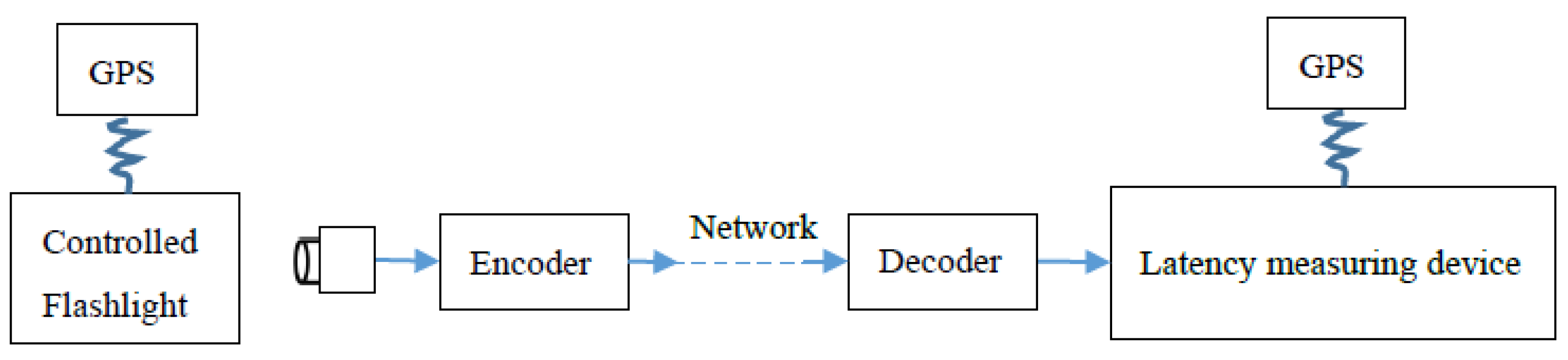
Although Method 1 has higher measurement accuracy, it needs to connect both the video of the sender and the video of the receiver to the same latency measurement device. Due to this limitation, remote video transmission cannot be measured. To this end, we designed Method 2, and the measurement scheme is shown in
Figure 4. The solution includes a flashing light and a latency measurement device at the remote receiver. Time synchronization of remotely located measuring equipment uses GPS signals. The flashing light is controlled by the GPS PPS (pulse per second) to flash once per second, and the camera will send the captured pictures including the flashing light to the latency measurement device through the video transmission system. The device records the time when each frame enters the device and finds the frame when the flashlight just starts to light up. The fractional part of the time (in milliseconds) that the frame with the light on enters the device is the end-to-end latency of the video transmission.
The PPS signal that controls the flash has precise clock synchronization and the signal accuracy is less than 50 ns. The PPS signal of the GPS module we use is a pulse signal with a period of one second and a pulse width of 200 ms. The PPS signal controls the power switch to drive the light to flash, so that the flashing light flashes once per second, lasting 200 ms each time. The latency measurement device adopts a 32-bit counter driven by a 25 MHz clock as the timing value. When the device is powered on, the 32-bit timing counter is reset by the rise of the PPS signal. In normal operation, the rising edge of the PPS signal is used to reset the timer counter once every 10 min to ensure the time synchronization between the flashing light and the latency measuring device.
Taking a 720p@60 camera as an example, when the light is on for 200 ms, the video shot will have approximately 12 consecutive frames in which the light is on. The video enters the latency measurement device through encoding, transmission, and decoding. The measurement device compares the brightness values of the previous and previous frames for five consecutive frames. The device determines that there is a partial increase in brightness in a frame, that is, the light is on, and continuously observes whether the position continues to remain in the next 4 frames. If the position maintains the brightness, it can determine the frame when the light just began to turn on. A 32-bit counter value
is recorded representing the time the frame during which the latency measurement device entered, I represents the number of measurements.
can be converted into real-time
in seconds. It can be expressed by Equation (4):
The fractional part of timing time
is the end-to-end latency value
of video transmission, it can be expressed by Equation (5):
Compared with Method 1, Method 2 is simple in operation and does not need to access the original video and the reconstructed video from the measurement device at the same time. It only needs to place the flash device in the field of view of the camera and connect the decoded reconstructed video to the latency measurement device to complete the latency measurement. Method 2 realizes remote measurement, but the disadvantage of Method 2 is that it is still a lossy video measurement, because the flashing light must be in the video content, which partially destroys the original video picture. Method 2 uses the camera to shoot the flashing light to determine the same frame, the shooting may have a delay within one frame, and the measurement error is large. The biggest limitation is that, because GPS signals cannot be received indoors, this method can only be used for outdoor measurements.
3.3. Method 3: Lossless Remote Video Online Measurement
When using Method 2 for measurement, both the sender and the receiver must have GPS signals and the measurement accuracy is low. For this reason, we developed a method that can accurately measure the end-to-end latency of remote video without loss based on the IEEE1588 time synchronization protocol. The measurement scheme is shown in
Figure 5.
A latency measurement device is placed at the transmitter and receiver of the remote video transmission system, respectively, and the device uses the built-in IEEE1588 protocol to achieve time synchronization. The original video and the reconstructed video are copied and connected to the transmitter latency measurement device and the receiver latency measurement device, and no changes are made to the video transmission system. The sending-end latency measuring device calculates the hash value of each input frame and combines it with the entry time of the frame to package and send it to the receiving-end latency measuring device through the network. The latency measurement device at the receiving end calculates the hash value according to the same algorithm for each frame of the reconstructed video and stamps it with a time stamp. At the receiving end, the latency measurement device matches the hash value of the original video frame and the hash value of the reconstructed video frame, and a successful hash value matching indicates that the corresponding frame is determined. The end-to-end latency of the frame can be obtained by comparing the timestamps of the corresponding frames.
In order to accurately find the correspondence between the reconstructed video and each frame of the original video, this method uses video-aware hashing technology, which includes three processing contents: feature information extraction, video-aware hash extraction, and hash code matching. Most video codecs based on hybrid coding frameworks use motion search for predictive coding, therefore, this method selects motion information features of video frames as hash feature information to reflect changes in video content. Different from the commonly used video-aware hashing algorithm based on gradient orientation centroids, this method chooses to use a difference-valued hash-aware compression algorithm. In order to ensure the accuracy of the measurement, the measuring device at the sending end and the measuring device at the receiving end must maintain time synchronization. In order to ensure the accuracy of the measurement, the measuring device at the sending end and the measuring device at the receiving end must maintain time synchronization. We adopt the IEEE 1588 protocol and implement it in software, which can achieve a synchronization accuracy of 20 ns under a 100 ms synchronization period, which meets the requirements for accurate online measurement of video transmission delay [
48]. The specific processing flow is shown in
Figure 6.
Taking the original video sequence with a resolution of 1280 720 as an example, the reconstructed video sequence after encoding and decoding is , where (i, j) represents the pixel coordinates in the video, n and m, respectively, represent the n and m frames of the original video and the reconstructed video. The luminance components and of the original video and the reconstructed video are selected for subsequent processing.
The latency measurement devices at the sending end and at the receiving end record the input time of each frame of the original video and the reconstructed video. When the device detects the frame synchronization pulse of each frame, it records the value of the 32-bit counter driven by the internal 25 MHz clock as the time stamp of the frame input to the latency measurement device. The time represented by the counter is guaranteed to be synchronized by the IEEE1588 protocol inside the sender and receiver devices.
In order to reduce the amount of data to be processed while retaining useful information, the original video frame and the reconstructed video frame are subjected to block and down sampling processing. The device divides the
and
frames into 16
16-pixel blocks and assigns the average pixel value of each block to
and
, as shown in Equation (6). The downsampling of the original video frame and the reconstructed video frame is realized, and the original video frame sequence
and the reconstructed video frame sequence
, with a resolution of 80
45, are obtained, where
.
The downsampled original video sequence
and the downsampled reconstructed video sequence
are subjected to frame difference processing according to Equation (7), and obtain the video sequence s
and
that reflect the pixel changes of the previous and previous frames.
A threshold value
is selected to binarize
and
according to Equation (8). The pixel value greater than the threshold value is set to 1 and the pixel value less than the threshold value is set to 0 to obtain binarized images
and
.
where
represents the pixel value of the pixel with coordinate
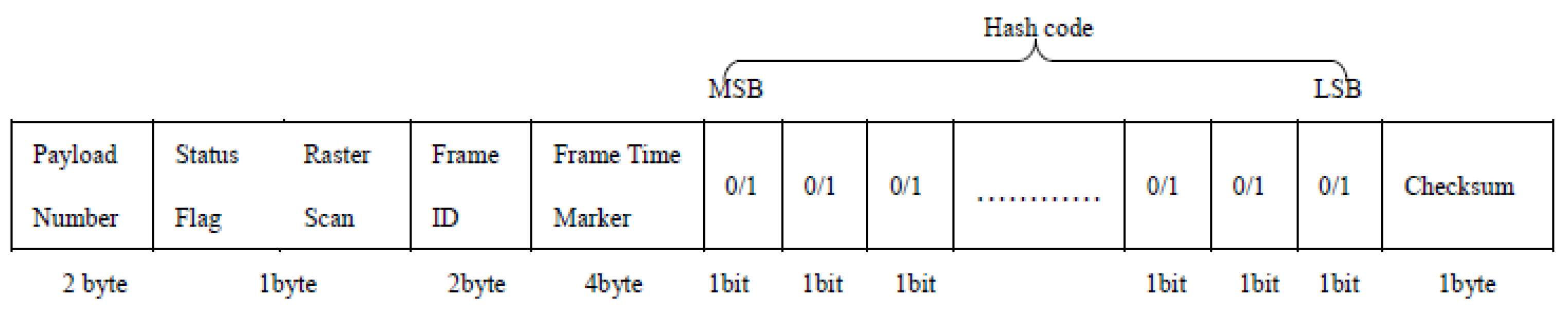
. The binarized image is expanded line by line to obtain the hash codes of each frame of the original video and the reconstructed video. The hash code and frame timestamp of each frame of the original video are composed of hash packets which are packaged and sent to the latency measurement device at the receiver, as shown in
Figure 7.
The latency measurement device at the receiver performs hash matching to find the original video frame that matches the reconstructed video. In the hash library, HashBD, at the receiver,
and
are used to represent the hash codes of the original video frame and the reconstructed video frame respectively, and
,
is the value of the kth bit of the hash code. The Hamming distance is used to calculate the distance of two code strings, that is, the corresponding bits of the reconstructed video frame feature hash value and the original video frame feature hash value are XOR processed and the number of 1 is counted, as shown in Equation (9). The distance determines the correspondence between two frames. The smaller the distance, the stronger the correlation between the two frames, and the less the correlation. In this way, the original video frame matching with the reconstructed video frame can be found, and the end-to-end latency of video transmission can be obtained by using the time stamps carried by the two video frames.
Method 3 can carry out high-precision real-time latency monitoring online without damaging the transmitted video. It balances the tradeoff between computational demand, out of band bandwidth utilization, and robustness across different content. The test accuracy is similar to that of Method 1, and the remote measurement function of Method 2 can be realized and is not limited to the scenario with a GPS signal. It can be used as a convenient, continuous, and reliable method for popularization and application.
4. Evaluation
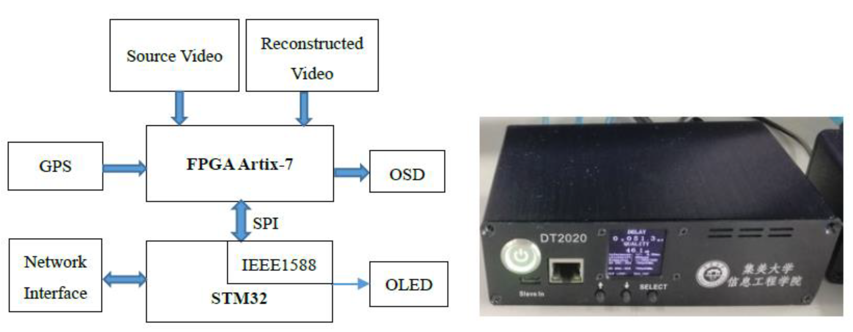
Combined with the requirements of the above three latency measurement methods on the latency measurement device, we designed a latency measurement device that can meet the requirements of the three measurement methods and implemented the hardware implementation. The design framework and physical drawing are shown in
Figure 8, and the device is named CC3030. The device framework is mainly composed of heterogeneous systems based on Xilinx ARTIX-7 series FPGA and STM32F7 series MCU. Among them, FPGA is mainly responsible for image information processing and STM32 is mainly responsible for data processing and external interaction. The information processed by FPGA is transmitted to the STM32 microcontroller and the microcontroller calculates the latency. The device provides two HDSDI ports and two HDMI ports for video input and one HDSDI and one HDMI for OSD (On Screen Display) menu display. It can receive external GPS signals and the device’s configuration and measurement results can be seen on other devices’ web pages through the network port.
The following is an example of three latency measurement methods using different configurations of this self-made CC3030. The camera model used in the measurement is SHD60 and the two codec systems are H.264 codec and H.265 codec. H.264 codec was selected from Sculpture Networks. The encoder model was Snenc1000 (for San Diego, CA, USA), and the decoder model was Sncupid1000 (for San Diego, CA, USA). H.265 codec is the codec used by Huawei Hislicon HI3519 video codec solution.
4.1. Method 1: Timecode Method
The method requires a camera, two display screens, an allocator, codec, and a CC3030 before the measurement. The camera is used for real-time video acquisition and the captured video is passed through a 12 G SDI video one-in, two-out splitter to obtain two-channel zero-time latency video. One input is raw video to the display screen, the other input is CC3030. The original video sequence input to CC3030 is called the source video, and the video input is called the source entry (Ori). The source video is output from CC3030, and, after passing through the codec, the reconstructed video is obtained. The reconstructed video is fed into CC3030, which is called the reconstructed entry (Rec). The time stamp in the reconstructed video is found by FPGA in CC3030 and the transmission latency of the video sequence is determined by comparing it with the local time. In order to facilitate the display of the latency measurement results on the reconstructed video, the displayed time bit is controlled at 0.1 ms.
The video input and output in the measurement process need to pass through the video interface (HDSDI or HDMI). The latency caused by these interfaces is measured in microseconds, which is negligible compared to the latency of measuring video transmission. Since the timestamp is embedded in the existing video source, the latency caused by camera acquisition is not included in the latency measurement results.
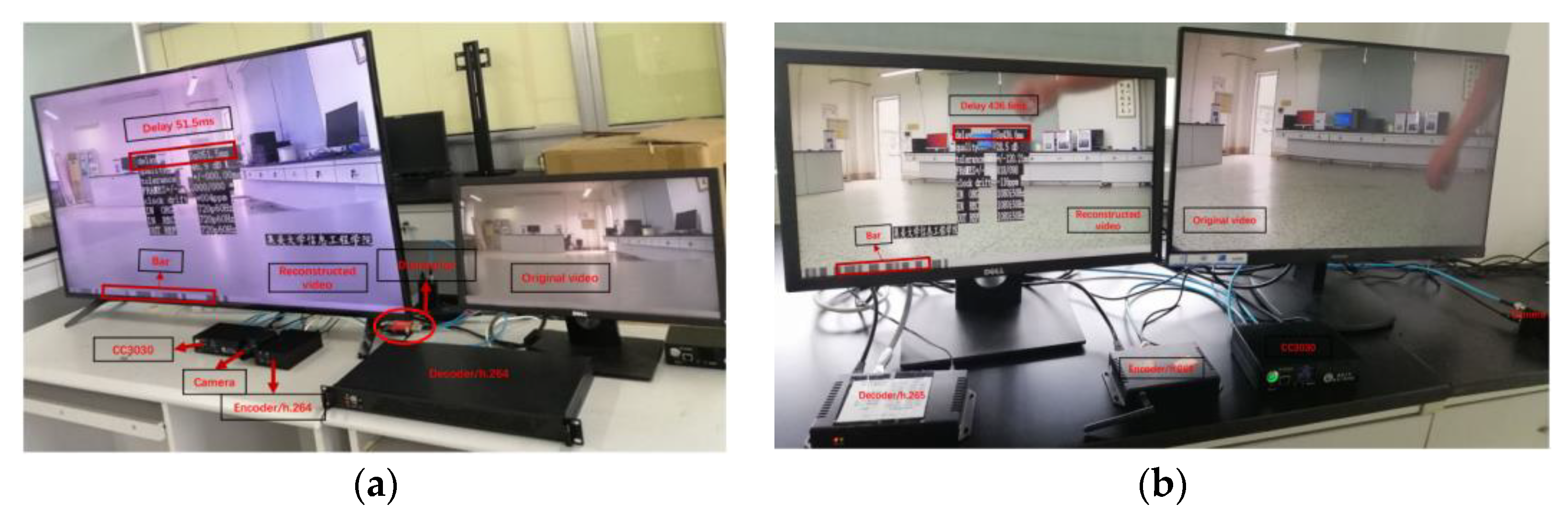
Figure 9a is the latency measurement process of video transmission through the H.264 codec. In the image, the right screen shows the original video, and the left screen shows the reconstructed video with the measurement results, and the time stamp is presented as a spline at the bottom of the screen. It can be seen that the real-time video acquisition format of the measurement process is 720P60HZ and the latency measurement result is 51.5 ms.
Figure 9b shows the latency measurement process of video transmission through the H.265 codec. In the same picture, the right screen is the original video and the left screen is the reconstructed video with the measurement results. The real-time video acquisition format of the measurement process is 1080i50HZ and the latency measurement result is 436.6 ms.
4.2. Method 2: Remote Online Measurement
The method requires a camera, a display, a flash, a codec, and a CC3030 before the measurement. In this experiment, the flashing light flickered once every second for 200 ms. When using the camera to capture video, we must ensure that the flashing light is in the capture picture.
When the PPS signal from GPS arrives, the lights start flashing and CC3030 also starts the timing operation. The flash video picture captured by the camera is transmitted and the reconstructed video is obtained at the decoding end. The reconstructed video is input to CC3030 and the FPGA in the device obtains the flashing picture and stops the timing operation after finding it. Finally, the measurement results are printed on the reconstructed video and displayed on the screen.
The frequency of flashing light in this measurement is 1 s. The frequency of the flash determines the range of the measured latency. If the frequency of the flashing light is less than the latency of the transmission system when the FPGA searches for the flashing picture, the latency measurement error will occur due to the stacked flashing picture of the system. Therefore, it is necessary to change the flashing frequency when measuring the transmission system with large latency.
Figure 10a shows the latency result of directly inputting the flash picture collected by the camera into CC3030 without going through the codec, which is the latency of the camera. As can be seen, the video acquisition format is 720P60HZ and the time latency of the camera used for measurement is 34.9 ms.
Figure 10b shows the latency result after the video source is transmitted by the codec. The codec selected for measurement is the H.264 video codec and the video acquisition format is 720P60HZ. It can be seen that the latency generated in the video transmission process is 96.4 ms and 61.5 ms can be obtained after removing the latency caused by the camera video acquisition.
4.3. Method 3: Lossless Remote Video Online Measurement
It is necessary to prepare one CC3030 at the transmitter and one at the receiver before measurement. Since it is impossible to ensure that both the transmitter and receiver of remote video transmission can receive GPS signals, the IEEE1588 protocol is used to realize time synchronization between the transmitter and receiver. In the measurement process, two transmission channels are carried out synchronously. One method is the transmission of the original video to obtain the reconstructed video. The other method is to process the original video and reconstruct the video. At the sending end, the original video is input to CC3030 and the hash code of the original video is obtained. At the receiver, the reconstructed video is input into CC3030 and the hash code of the reconstructed video is obtained. The original video hash code with time stamp is transmitted to the receiver CC3030 through the network, and the original video frame hash code matching the reconstructed video frame hash code is found. The video transmission latency is obtained by using the timestamp carried in their hash codes.
The codec system used in this measurement is the H.264 codec.
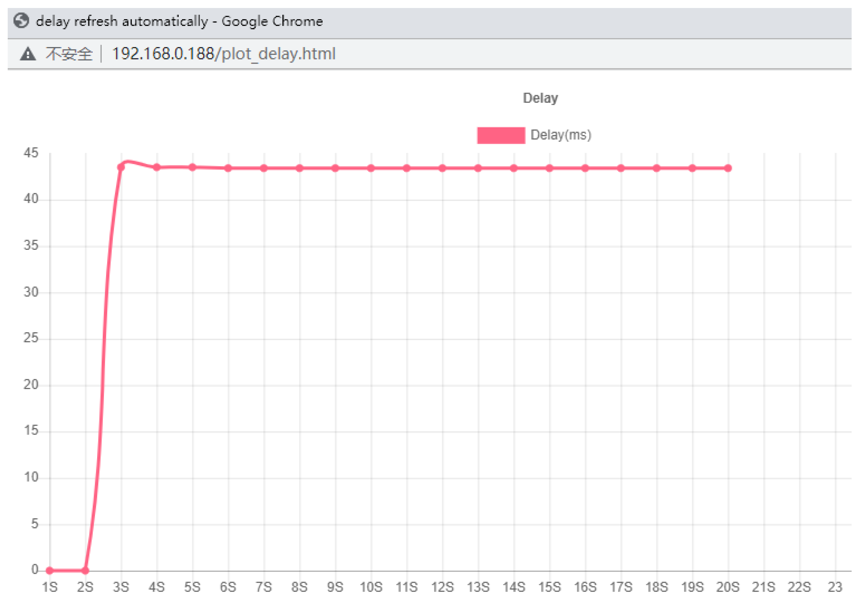
Table 1 shows the timestamp of the first 10 s of the reconstructed video and the matched original video frame and calculates the delay value. Due to the limitation of the distance between the sender and the receiver, the latency measurement results are designed to be real-time output in the form of web pages, where the horizontal coordinate is time, the unit of second represents the monitoring once a second in actual operation, and the vertical coordinate is the latency value, the unit of which is millisecond, as shown in
Figure 11.
4.4. Comparison of Proposed Methods with Existing Methods
Based on the actual evaluation results, the advantages and disadvantages of the three measurement methods are listed, as shown in
Table 2.
The measurement principle of Method 1 is the same as that of Method 3 and Method 3 uses out-of-band hash data and ieee1588 time synchronization to realize lossless remote measurement. The time value in the actual measurement uses a 32-bit counter that counts with a 25 MHz clock. Therefore, the minimum time unit of the timestamp in Method 1 and Method 3 is 40 ns. According to Equation (2), the maximum error between the arrival time of the reconstructed video and the arrival time of the original video due to ±1 error is 80 ns and the accuracy is set as 0.1 us for statistical convenience. The measurement principle of Method 2 is similar to that of Reference [
30]. Reference [
30] measures time delay introduced by a video transmission system under test to the propagation of light from a light-emitting diode (LED) to a phototransistor (PT). The resistance of the PT decreases when the LED lights up in the displayed image. The sampling rate of PT is 2 kHz, yielding a precision of 0.5 ms. However, the measurement relies on the output of the display with a video camera, and it has limited precision of, e.g., 16.7 ms for a 60 Hz video camera. The actual precision of Reference [
30] is subframe, the same as Method 2. The work in [
26] uses an embedded barcode to measure the end-to-end delay of computer video chat applications. The precision of the method is subframe due to the influence of screen refresh and software execution speed. Reference [
5] measures latency by waveform shift on an oscilloscope. The measurement accuracy can be guaranteed, but it is very inconvenient and cannot be measured online.
5. Summary
In this paper, the generation of latency in video transmission is analyzed and three latency measurement methods are proposed: timecode method, remote online measurement method, and lossless remote video online measurement method. Depending on the deployment scenario, different time latency measurement methods are suitable. The measurement accuracy of Method 1 and Method 3 is similar, but Method 1 is only suitable for local measurement, where the source content is modified with a timestamp. This paper proposes a synchronization framework for Method 3 that balances the out-of-band bandwidth, the measurement accuracy, and the deployment ease using video-aware hash tables. Both Methods 2 and 3 can be used to measure the latency of remote video transmission, but Method 3 does not alter the original video content. One unique value of Method 2 is that it captures the latency of the capturing and the rendering devices (e.g., camera, display). Compared with Methods 1 and 2, Method 3 can achieve high-precision lossless remote video online latency measurement. Method 3 is scalable through today’s networks, providing continuous monitoring. This will bring the latency QoS to a level that is then acceptable for next generation applications, including VR and real-time AI solutions.
In the future, Method 3 can be integrated into cameras, and can directly measure the camera latency. If the camera contains an encoding and decoding system, the video transmission latency can be obtained directly. Furthermore, Method 3 can be extended to not only measure the video transmission latency, but also detect the frame loss in the transmission process.


