Article

Quantification of Magnesia Dissolution in Silicate Melts and Diffusivity Determination Using Rotating Finger Test

Montanuniversitaet Leoben, Peter-Tunner Straße 5, 8700 Leoben, Austria
*
Author to whom correspondence should be addressed.
Appl. Sci. 2022, 12(24), 12791; https://doi.org/10.3390/app122412791
Submission received: 21 November 2022 / Revised: 7 December 2022 / Accepted: 9 December 2022 / Published: 13 December 2022
(This article belongs to the Topic Innovative Construction and Building Materials)

Abstract

:
Refractories exposed to corrosive melts at high temperatures experience wear due to dissolution. The presented work deals with the dynamic corrosion of magnesia fine ceramics in a CaO–Al2O3–SiO2–MgO silicate slag with a CaO/SiO2 weight ratio of 0.65. Finger tests at 200 rpm at three different temperatures, 1450, 1500, and 1550 °C, were performed. A contemporary rotary finger test (RFT) device with in-situ wear profile measurement using a laser device was used. The precise dimension measurements with high-resolution facilitate the determination of total mass flux densities, which allow for determination of effective binary diffusivities. Thereby, two methods based on Sherwood relations were applied. The comparison shows the benefit to better consider deviations from pure cylinder shape. The use of contemporary RFT devices and magnesia fine ceramics allows reliable determination of the effective binary diffusivity.

1. Introduction

Magnesia is an important refractory component in the ferrous, non-ferrous, and cement industries [1,2,3,4,5,6,7,8]. In many cases, these refractories are exposed to corrosive melts at high temperatures and experience wear due to dissolution during their service. Comprehensive dissolution studies and accurate quantification of the dissolution are required to reduce the wear rate of refractories, enhance their life, and improve the cost and resource efficiency [9,10,11,12,13,14,15,16,17,18,19,20,21,22,23]. In general, dissolution is controlled by diffusion in the liquid phase. Therefore, the diffusivity of the dissolving species is the key parameter of interest for the quantification of dissolution [5,15,18,24,25,26,27,28,29,30,31,32,33,34,35].
The following section addresses state of the art methods for quantification of dissolution: A major challenge for this quantification is the requirement for a correct representation of the effective diffusive boundary layer thickness. The rotary finger test (RFT) can be used to address this challenge because the technique allows for the control of effective diffusive boundary layer thickness via experimental parameters, such as the geometry of the sample and crucible assembly, Reynolds number, and Schmidt number [15,28]. RFT has been widely used to study the continuous wear of refractory materials in corrosive melts [2,3,8,11,29,30,36,37,38,39,40,41,42,43,44,45,46,47,48,49,50,51,52]. All these studies are based on post-mortem analysis. Some of them focus on microstructure evaluation [2,3,36,44,46,47] without quantifying the refractory wear; some other RFT studies [8,11,29,30,37,38,39,40,41,45,48,50,52] use the change in the dimension to quantify continuous refractory wear. High-temperature confocal laser scanning microscopy (HT-CLSM), which can be used for in-situ measurements, is also an important technique in the state-of-the-art for continuous wear studies. Recently, a contemporary continuous wear testing device (CWTD) featuring in-situ wear profile measurement with a high-resolution laser has been reported [53]. Compared to the manual dimension measurement during a post mortem analysis, the laser measurement is expected to be more accurate as a huge number of measurement points image the whole refractory surface while manual measurements are restricted to few locations on the rough sample surface [15]. In this study, CWTD was used to take advantage of its high-resolution in-situ measurement. Although dissolution has been studied using HT-CLSM, the impacting phenomena and parameters, such as the Stefan flow and the effect of bath movement, were not considered in the evaluation [18,24,25,26,27,31,32,33,34,35,54,55,56,57]. Accounting for the Stefan flow and the effect of bath movement necessitates the application of the diffusion-convection equation. The Stefan flow was considered in Ref. [58], but the effect of bath movement was not considered; however, both parameters were considered in Ref. [28].
The literature about magnesia dissolution reveals the following: The dissolution of magnesia in different slags using HT-CLSM and the corresponding diffusivity determination were reported previously [18,27,34,57]. In those studies, magnesia particles of irregular shape were used, and the diffusivity determination models were based on spherical particles; this could lead to incorrect results, especially at the beginning of the dissolution. Some researchers have used RFT to quantify continuous wear using cylindrical magnesia samples [8,21,38,48]. The results obtained from RFT are expected to be more accurate than CLSM studies because the effective diffusive boundary layer thickness could be defined in RFT by the experimental parameters [28]. However, the determination of the diffusivity of magnesia from RFT has not yet been studied. Um et al. [38] and Jansson et al. [8] calculated the mass transfer coefficients from RFT experiments with MgO-C refractories; however, the mass flux used in their calculation includes the erosive mass flux in addition to the corrosive flux due to the limited erosion resistance of a cylindrical ordinary ceramic MgO-C material. Ordinary ceramic materials with a maximum grain size of several millimeters are widely studied. However, to the best of our knowledge, dense magnesia fine ceramics, which are necessary for diffusivity determination from solely corrosive mass flux, have not yet been investigated. This may be the primary reason for the lack of magnesia diffusivity data from RFT studies. Therefore, to obtain reliable results solely from the corrosive mass flux, RFT studies with fine magnesia ceramics are necessary.
In this study, we investigate the dynamic corrosion of fine magnesia ceramics and determine the effective binary diffusivities of magnesia in silicate slags. Cylinders of magnesia fine ceramics were used for the RFT experiments in silicate slag with a CaO/SiO2 weight ratio of 0.65 at 1450, 1500, and 1550 °C with 200 rotations per minute (rpm). The diffusivity calculation technique based on the Sherwood relation was adopted from Ref. [15]. The Arrhenius plot was used to test for plausibility of the diffusivities [15]. All the diffusivity values quoted in this study are effective binary diffusivities.

2. Materials and Methods

2.1. Materials

Decarburized calcium carbonate, alumina, quartz, and magnesia powder (S3 Handel und Dienstleistungen UG, Bad Oeynhausen, Germany) were used to produce synthetic silicate slag. At first, decarburization of calcium carbonate and dehydration of magnesium oxide (to eliminate hydration by atmospheric moisture) were carried out at 1050 °C for 3 h. To ensure complete decarburization, the weight loss was checked after each round of decarburization, and the slag components were immediately weighed to avoid prior hydration due to atmospheric moisture. Table 1 lists the slag properties including the density and liquidus temperature. The CaO/SiO2 weight ratio of 0.65 was used, which is low enough to ensure higher dissolution rate of magnesia. The slag densities for three experimental temperatures were calculated according to the method described by Xin et al. [59]. The viscosities of the original slag and magnesia-saturated slag and the saturation limits of magnesia in this slag at different temperatures are shown in Figure 1. The thermochemical software, FactSage 7.3 (CRCT, Montreal, QC, Canada) was used to calculate the viscosities, liquidus temperature, and magnesia saturation limits in the slag [60]. Figure 1 shows that the viscosity is lower for the magnesia-saturated slag because of the increase in non-bridging oxygen due to the introduction of magnesia. Moreover, the decrease in viscosity at a lower temperature is larger than that at a higher temperature.
The dissolution of magnesia fine ceramics (Surtec Research Europe GmbH, Düsseldorf, Germany) with 99.6 wt% MgO, 3.40 g/cm3 bulk density, and water absorption of 0% was investigated in the silicate slag. The diameters and lengths of the magnesia cylinders were 20 mm and 110 mm, respectively. To aid fixing the cylinder with the rotor shaft of the testing setup, all the samples had an axial drill with a diameter of 5 mm and depth of 32 mm, and a diameter of 3.5 mm horizontal drill.

2.2. Experiment

In this study, rotary finger test experiments of magnesia dissolution were conducted using a contemporary continuous wear testing device (CWTD) at 1450, 1500, and 1550 °C with 200 rpm. A comprehensive description of the testing device and measurement techniques are available in Ref. [53]. The experimental procedure was similar to that used in alumina dissolution, as reported in Ref. [15]. For every experiment, 580 g of slag was melted in two steps in a platinum-10wt% rhodium (Pt-Rh10) crucible with an inner diameter of 65 mm and a height of 100 mm. Approximately 380 g of slag was pre-melted, and the rest of the slag was melted during the CWTD experiment. The target slag-bath-height was approximately 70 mm without the submerged sample and approximately 75 mm with the sample. Initially, the gap between the crucible bottom and the sample lower end was set to approximately 20 mm, and it increased continuously with the decrease of sample length. The heating and cooling rates of the CWTD furnace were set at 5 °C/min [15]. A temperature of 5 °C below the target temperature was maintained for 1 h to achieve temperature homogeneity and complete slag melting. During heating and holding below the target temperature, the magnesia sample was placed above the slag-filled crucible, dipped 3 °C below the target temperature, and was set to rotate at 200 rpm for the defined dissolution time. 30, 25, and 20 min of corrosion time steps were programmed at 1450 °C, 1500 °C, and 1550 °C, respectively. Corrosion time step was varied to cope up different dissolution rates at various temperatures, which facilitated to obtain higher number of corrosion steps. After each corrosion step, the corroded sample was placed at rest above the crucible for 30 min for slag dropdown, and subsequently, a laser scan was performed to generate 3000 profiles [15].

2.3. Continuous Wear Curve Evaluation and Diffusivity Determination

Three thousand profiles were averaged in the circumferential direction after preprocessing to obtain a unique, axisymmetric, and representative mean corrosion profile (MCP) [15]. MCP facilitates the dimensional analysis of the sample. The details of profile processing can be found in Ref. [53]. The mass flux density was calculated using dissolution parameters obtained from the MCP and, subsequently, the diffusivity [15]. In conventional post-mortem analysis, the dimensions are measured manually at a small number of locations on the rough corroded samples. In contrast, laser measurements incorporate dimension information from the entire sample surface with a high resolution. Hence, the dissolution parameters from MCPs obtained using laser measurements are anticipated to be precise than those obtained using conventional methods. In the dissolution experiments at all three temperatures, Marangoni grooves were observed at the refractory-slag-atmosphere triple point of the magnesia cylinders. The diffusivity determination method is based on the total mass flux density solely due to forced convection. Therefore, separating the mass fluxes due to Marangoni convection and forced convection is necessary; this separation can be performed easily by identifying the groove length from the MCP. Dissolution from the groove was considered only when the bulk slag composition and the corresponding slag viscosity for different corrosion steps were calculated, as these two parameters are related to the total dissolution. Other dissolution parameters, such as the mean corroded radius, immersion length, and mass flux density were considered for determining the diffusivity; however, the dissolution from the groove was not considered. In this study, the diffusivities of magnesia were determined according to the method reported by Burhanuddin et al. [15] using Equation (1). This was derived from the total mass flux density using Sherwood relations for the mantle and bottom of the cylindrical sample [15]. The method reported in Ref. [15] uses the modified Sherwood relation proposed by Tachibana and Fukui [61] (Equation (3)) for the mantle of the cylindrical sample. Instead, herein, the Sherwood relation proposed by Guarco et al. [62] (Equation (2)), derived from the simulations for the same experimental setup, was adopted. Moreover, as in Ref. [15], the Sherwood relation reported by Levich [63] was also employed here for the bottom of the sample.
D = j · 1 + 0.566 · B · 2 l · R 1 + R t 2 ρ s · B · 0.2 · l 0.68 · R 1 0.81 · ω 0.65 · ν 1 3 0.65 · R 2 R 1 0.49 · B C 0.32 + 0.62 · R t 2 · ω 1 2 · ν 1 6 3 2
S h G = 0.10 · R e 0.65 · S c 1 / 3 · R 2 R 1 / R 1 0.84 · B C / l 0.32
S h T = 0.21 · R e 1 / 2 · S c 1 / 3 · R 2 R 1 / R 1 0.25
where D is the effective binary diffusivity; j , the mass flux density; B , the dimensionless concentration difference: B = w s w 0 / 1 w s , where w 0 and w s , respectively, denote the mass fraction of dissolving species in the bulk slag and saturated slag; R 1 , the mean cylinder radius; R 2 , the crucible radius; R t , the tip radius; l , the immersion length; ν , the kinematic viscosity of the slag; ω , the angular velocity; B C , the bottom clearance i.e., the gap between the sample tip and crucible bottom; and ρ s , the density of the slag. S h , is the Sherwood number; R e , the Reynolds number; and S c the Schmidt number. The characteristic length for S h and R e is the gap width R 2 R 1 in both Sherwood relations (Equations (2) and (3)).
A number of corrosion steps i were evaluated, and the quantity D i was calculated for each step according to Equation (1). For all the time-dependent parameters on the right-hand side of Equation (1), the mean value of steps i 1 and i was substituted to better fit the time interval ( t i 1 , t i ) of corrosion step i . Moreover, D i , the mean of all corrosion steps with t t i was calculated and is denoted as D 0 , i .

3. Results and Discussion

3.1. Mean Corrosion Profiles

Laser measurements were captured before dipping into the slag (i.e., after a holding time at 5 °C below the target temperature) and the MCP generated thereby was used as the reference curve to quantify all the dissolution parameters. Moreover, the laser measurements were also performed after each corrosion step and a corresponding MCP was generated. The MCP has two key benefits [15]: First, the nonconcentric rotation of the sample during laser measurements leads to a slight inclination of the individual profiles from the axis of rotation, and this inclination can be eliminated by averaging all the individual profiles. Second, the dimension analysis is ambiguous for all profiles because of non-axisymmetric corroded sample; the MCP provides an equivalent axially symmetric shape, which is the representative sample geometry, and the dissolution parameters can be easily extracted. Figure 2 shows the MCPs for the magnesia dissolution at 200 rpm and 1450, 1500, and 1550 °C. The Marangoni groove was present in all the cases. The experiment with all the planned corrosion steps could be completed at 1450 °C. At temperatures 1500 °C and 1550 °C, the experiments were aborted after seven and four corrosion steps, respectively, due to the higher corrosion depth at the Marangoni groove. The groove depth after a particular corrosion time was larger at higher temperatures. The Marangoni groove length increased with an increase in the corrosion time. The dissolution from the middle of the corroded part was lower than that of the other parts. The uncorroded portions of all the MCPs overlap with one another and with the MCP of the virgin sample. The radius and length of the corroded sample decreased with an increase in the corrosion time. For a given corrosion time, the corresponding reduction was higher with rising temperature. Figure 3 shows the virgin and corroded samples at the end of the experiment. The MCPs for the last corrosion steps accurately portray the corroded sample geometry. A slag droplet, which should be liquid and transparent at the target temperature, was present at the bottom tip of the corroded samples.

3.2. Dissolution Parameters
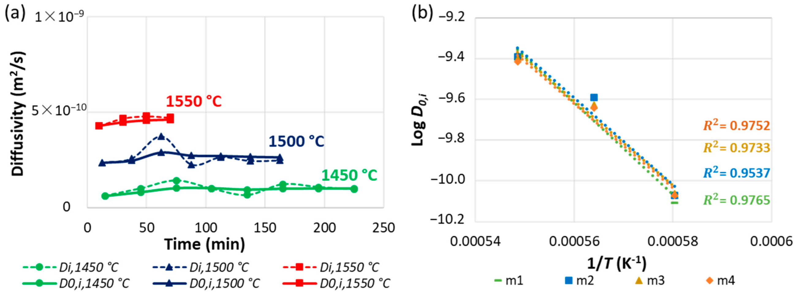
The corroded volume, surface area, mean radius, tip radius, and immersion length, were calculated from the MCPs of all individual steps [15]. Figure 4 shows the changes in the sample length, mean corroded radius, volume, and mass as a function of the dissolution time for the magnesia dissolution at 200 rpm and 1450, 1500, and 1550 °C. All the parameters herein were determined by excluding the grooves. However, the concentration of magnesia in the bulk slag and the corresponding slag viscosity depend on the total amount of dissolved magnesia; hence, the mass flux from the groove was included in calculating these parameters. The absolute value of all the parameters increased with an increase in the experimental temperature due to the lower slag viscosity and larger solubility limit at higher temperatures. The absolute values of the average rate of volume loss from the grooves alone were 4.4, 10.8, and 23.0 mm3/min at 1450, 1500, and 1550 °C, respectively, thereby contributing 16, 19, and 23% to the total volume loss rate. With an increase in the temperature from 1450 °C to 1500 °C, the mean rates of change in the mean corroded radius, volume, and mass rise 2.0–2.2 times; moreover, with a temperature increase from 1500 °C to 1550 °C, the mean rates of change in the quantities rise 1.7–2.0 times. The mean rate of change in the sample length amplified 2.27 times when the temperature increased from 1450 °C to 1500 °C, and it increased 1.16 times when the temperature increased from 1500 °C to 1550 °C. A marginally declining slope or an nearly linear trend in the dissolution parameters designates quasi-steady dissolution [15].

3.3. Diffusivity

The dissolution quantities calculated from the MCPs are tabulated in Table 2. Using these quantities, the diffusivities for all the individual corrosion steps at the three experimental temperatures were determined according to Equation (1) [15,62]. Figure 5a shows the diffusivities ( D i and D 0 , i ) of magnesia for all the corrosion steps. The diffusivity amplified with a rise in the temperature. At a given temperature, the slag viscosity decreased with magnesia dissolution, which possibly led to moderate rise of diffusivity. The Arrhenius plot was obtained using the diffusivities ( D 0 , i ) at the corresponding corrosion steps i T (the corrosion step i at temperature T ): the specimen mass loss with respect to the original mass at different temperatures was similar. The obtained diffusivities are functions of the temperature and slag composition, which change during the experiment [15]. For the Arrhenius plot, the diffusivities were transformed to those of the virgin slag composition, assuming that the product of the diffusivity and viscosity was constant, which is in agreement with the Stokes–Einstein relation [15]. This conversion eliminated the composition dependency: otherwise, the amount of magnesia in the slag would have been an additional influencing factor [15]. Figure 5b depicts the Arrhenius plot. The plausibility of the diffusivities was confirmed by the linear propensity of the Arrhenius plot [15]. The test intervals used for the Arrhenius plots, together with the associated mass loss, bulk concentrations of magnesia, and the corresponding activation energies, are listed in Table 3. The activation energy of diffusion decreases with a rise in the mass loss and bulk concentration.
It is of interest to compare the effective binary diffusivities of magnesia obtained using two different Sherwood relations (according to the modified Tachibana and Fukui equations [15,61] and Guarco et al. [62]) for the mantle of a cylindrical sample. The Sherwood relation, according to Levich [63], was applied to the bottom of the cylinder in both cases. Table 4 shows a comparison between the diffusivities at individual corrosion steps at the three experimental temperatures. At 1450 °C, the error percentage was lower than that of the other temperatures. The errors were considerably larger for the final corrosion steps. This may be due to the deviation in the shape of the corroded sample from that of the cylinder. Results using the Sherwood relation proposed by Guarco et al. [62] are anticipated to be more correct here, because the Sherwood relation therein was derived from a simulation where the actual sample geometry was considered; the modified Tachibana and Fukui relations, in contrast, considered a cylindrical sample shape. When the average diffusivities of all the corrosion steps at a particular temperature were compared, the error percentages were 1.74, 19.02, and 16.92 at 1450, 1500, and 1550 °C, respectively, indicating that both the Sherwood relations work reasonably well. Equality of the means was tested statistically with help of an independent two-sample t-test that is two-tailed. At a 5% significance level, the means for all three cases were proven to be equal.

4. Conclusions

Dynamic corrosion investigations of fine magnesia ceramics in silicate slag were conducted at 1450, 1500, and 1550 °C using CWTD with sample profile measurements at experimental temperatures. The dissolution quantities were calculated from the MCPs obtained using high-resolution laser measurements including the dimensions of the entire corroded sample surface. This enhanced the accurateness and trustworthiness of the results. The marginally declining slope or a nearly linear fashion of the dissolution quantities indicated quasi-steady dissolution. The Marangoni groove was present at all three experimental temperatures. The diffusivity of magnesia excluding the groove was successfully determined using the method based on Sherwood relations. The diffusivity of magnesia increased with the increasing temperature. At a given temperature, the increase in the diffusivity with the dissolution time was moderate, probably because of the decrease in the viscosity due to magnesia dissolution. The linear tendency in the Arrhenius plot confirmed the plausibility of the diffusivities, due to which, an accurate estimation of diffusivity at other temperatures can be obtained without performing the experiments. To evaluate the results for calculating effective binary diffusivities, the method that considers the deviations from the cylinder shape is recommended. Although these investigations were performed at 200 rpm, forced convection is expected to overrule the Marangoni convection at sufficiently high rotational speeds. This is the case when the critical Reynolds number ( R e c ) is exceeded. The identification of a quantitative relation defining such R e c is a potential future research direction.

Author Contributions

Conceptualization, B., H.H. and S.V.; Investigation—Performing experiments and evaluation of results, B.; Methodology, B.; Formal analysis, B. and S.V.; Validation, B.; Writing—original draft, B.; Visualization, B.; Writing—review & editing, H.H. and S.V.; Supervision, H.H. and S.V.; Resources, H.H.; Funding acquisition, H.H.; Project administration, S.V. All authors have read and agreed to the published version of the manuscript.

Funding

The authors gratefully acknowledge the financial support under the scope of the COMET program within the K2 Center “Integrated Computational Material, Process and Product Engineering (IC-MPPE)” (Project No 859480). This program is supported by the Austrian Federal Ministries for Transport, Innovation, and Technology (BMVIT) and the Digital and Economic Affairs (BMDW), represented by the Austrian Research Funding Association (FFG), and the federal states of Styria, Upper Austria, and Tyrol.

Informed Consent Statement

Not applicable.

Data Availability Statement

The data that support the findings of this study are available on reasonable request from the corresponding author.

Acknowledgments

Helpful guidance by Volkmar Kircher during the experimental procedures is gratefully acknowledged.

Conflicts of Interest

The authors declare no conflict of interest.

References

  1. Guo, M.; Parada, S.; Jones, P.T.; Van Dyck, J.; Boydens, E.; Durinck, D.; Blanpain, B.; Wollants, P. Degradation Mechanisms of Magnesia-Carbon Refractories by High-Alumina Stainless Steel Slags under Vacuum. Ceram. Int. 2007, 33, 1007–1018. [Google Scholar] [CrossRef]
  2. Guo, M.; Jones, P.T.; Parada, S.; Boydens, E.; Dyck, J.V.; Blanpain, B.; Wollants, P. Degradation Mechanisms of Magnesia-Chromite Refractories by High-Alumina Stainless Steel Slags under Vacuum Conditions. J. Eur. Ceram. Soc. 2006, 26, 3831–3843. [Google Scholar] [CrossRef]
  3. Chen, L.; Guo, M.; Shi, H.; Huang, S.; Jones, P.T.; Blanpain, B.; Malfliet, A. Effect of ZnO Level in Secondary Copper Smelting Slags on Slag/Magnesia-Chromite Refractory Interactions. J. Eur. Ceram. Soc. 2016, 36, 1821–1828. [Google Scholar] [CrossRef]
  4. Malfliet, A.; Lotfian, S.; Scheunis, L.; Petkov, V.; Pandelaers, L.; Jones, P.T.; Blanpain, B. Degradation Mechanisms and Use of Refractory Linings in Copper Production Processes: A Critical Review. J. Eur. Ceram. Soc. 2014, 34, 849–876. [Google Scholar] [CrossRef]
  5. Calvo, W.A.; Pena, P.; Tomba Martinez, A.G. Post-Mortem Analysis of Alumina-Magnesia-Carbon Refractory Bricks Used in Steelmaking Ladles. Ceram. Int. 2019, 45, 185–196. [Google Scholar] [CrossRef] [Green Version]
  6. Huang, A.; Wang, Y.; Zou, Y.; Gu, H.; Fu, L. Dynamic Interaction of Refractory and Molten Steel: Corrosion Mechanism of Alumina-Magnesia Castables. Ceram. Int. 2018, 44, 14617–14624. [Google Scholar] [CrossRef]
  7. Muñoz, V.; Camelli, S.; Tomba Martinez, A.G. Slag Corrosion of Alumina-Magnesia-Carbon Refractory Bricks: Experimental Data and Thermodynamic Simulation. Ceram. Int. 2017, 43, 4562–4569. [Google Scholar] [CrossRef]
  8. Jansson, S.; Brabie, V.; Jonsson, P. Corrosion Mechanism and Kinetic Behaviour of MgO-C Refractory Material in Contact with CaO-Al2O3-SiO2-MgO Slag. Scand. J. Metall. 2005, 34, 283–292. [Google Scholar] [CrossRef]
  9. Lee, W.E.; Zhang, S. Melt Corrosion of Oxide and Oxide–Carbon Refractories. Int. Mater. Rev. 1999, 44, 77–104. [Google Scholar] [CrossRef]
  10. Harmuth, H.; Vollmann, S. Refractory Corrosion by Dissolution in Slags—Challenges and Trends of Present Fundamental Research. Iron Steel Rev. 2014, 58, 157–170. [Google Scholar]
  11. Wang, Z.; Maotsela, T.; Toperesu, P.M.; Kale, G.M.; Daji, J.; Parkinson, D. Dynamic and Static Corrosion of Alpha-Alumina Bonded Refractory in Contact with Molten Soda-Lime-Silica (SLS) Glass. Ceram. Int. 2019, 45, 725–732. [Google Scholar] [CrossRef]
  12. Jansson, S. A Study on the Influence of Steel, Slag or Gas on Refractory Reactions. Doctoral Thesis, KTH Royal Institute of Technology, Stockholm, Sweden, 2008. [Google Scholar]
  13. Tang, H.Y.; Wu, G.H.; Wang, Y.; Li, J.S.; Lan, P.; Zhang, J.Q. Comparative Evaluation Investigation of Slag Corrosion on Al2O3 and MgO-Al2O3 Refractories via Experiments and Thermodynamic Simulations. Ceram. Int. 2017, 43, 16502–16511. [Google Scholar] [CrossRef]
  14. Cho, M.K.; Van Ende, M.A.; Eun, T.H.; Jung, I.H. Investigation of Slag-Refractory Interactions for the Ruhrstahl Heraeus (RH) Vacuum Degassing Process in Steelmaking. J. Eur. Ceram. Soc. 2012, 32, 1503–1517. [Google Scholar] [CrossRef]
  15. Burhanuddin; Guarco, J.; Harmuth, H.; Vollmann, S. Application of an Improved Testing Device for the Study of Alumina Dissolution in Silicate Slag. J. Eur. Ceram. Soc. 2022, 42, 3652–3659. [Google Scholar] [CrossRef]
  16. Reynaert, C.; Śniezek, E.; Szczerba, J. Corrosion tests for refractory materials intended for the steel industry—A review. Ceram.—Silik. 2020, 64, 278–288. [Google Scholar] [CrossRef] [Green Version]
  17. Park, J.H.; Park, J.G.; Min, D.J.; Lee, Y.E.; Kang, Y.-B. In Situ Observation of the Dissolution Phenomena of SiC Particle in CaO–SiO2–MnO Slag. J. Eur. Ceram. Soc. 2010, 30, 3181–3186. [Google Scholar] [CrossRef]
  18. Liu, J.; Guo, M.; Jones, P.T.; Verhaeghe, F.; Blanpain, B.; Wollants, P. In Situ Observation of the Direct and Indirect Dissolution of MgO Particles in CaO-Al2O3-SiO2-Based Slags. J. Eur. Ceram. Soc. 2007, 27, 1961–1972. [Google Scholar] [CrossRef]
  19. Cirilli, F.; Di Donato, A.; Martini, U.; Miceli, P.; Guillo, P.; Simoes, J.; Song, Y.J. Corrosion Mechanisms of Zirconia/Carbon Based Refractory Materials by Slag in Presence of Steel. La Metall. Ital. 2008, 100, 43–50. [Google Scholar]
  20. Baudín, C.; Criado, E.; Bakali, J.J.; Pena, P. Dynamic Corrosion of Al2O3–ZrO2–SiO2 and Cr2O3-Containing Refractories by Molten Frits. Part I: Macroscopic Analysis. J. Eur. Ceram. Soc. 2011, 31, 697–703. [Google Scholar] [CrossRef]
  21. Jansson, S.; Brabie, V.; Bohlin, L. Corrosion Mechanism and Kinetic Behaviour of Refractory Material in Contact with CaO–Al2O3–SiO2–MgO Slag. In Proceedings of the VII International Conference on Molten Slags Fluxes and Salts, Cape Town, South Africa, 25–28 January 2004; pp. 341–348. [Google Scholar]
  22. Braulio, M.A.L.; Martinez, A.G.T.; Luz, A.P.; Liebske, C.; Pandolfelli, V.C. Basic Slag Attack of Spinel-Containing Refractory Castables. Ceram. Int. 2011, 37, 1935–1945. [Google Scholar] [CrossRef]
  23. Goto, K.; Argent, B.B.; Lee, W.E. Corrosion of MgO-MgAl2O4 Spinel Refractory Bricks by Calcium Aluminosilicate Slag. J. Am. Ceram. Soc. 2005, 80, 461–471. [Google Scholar] [CrossRef]
  24. Sridhar, S.; Cramb, A.W. Kinetics of Al2O3 Dissolution in CaO-MgO-SiO2-Al2O3 Slags: In Situ Observations and Analysis. Metall. Mater. Trans. B 2000, 31, 406–410. [Google Scholar] [CrossRef]
  25. Valdez, M.; Prapakorn, K.; Cramb, A.W.; Sridhar, S. Dissolution of Alumina Particles in CaO-Al2O3-SiO2-MgO Slags. Ironmak. Steelmak. 2002, 29, 47–52. [Google Scholar] [CrossRef]
  26. Verhaeghe, F.; Liu, J.; Guo, M.; Arnout, S.; Blanpain, B.; Wollants, P. Dissolution and Diffusion Behavior of Al2O3 in a CaO–Al2O3–SiO2 Liquid: An Experimental-Numerical Approach. Appl. Phys. Lett. 2007, 91, 124104. [Google Scholar] [CrossRef]
  27. Valdez, M.; Prapakorn, K.; Cramb, A.W.; Seetharaman, S. A Study of the Dissolution of Al2O3, MgO and MgAl2O4 Particles in a CaO-Al2O3-SiO2 Slag. Steel Res. 2001, 72, 291–297. [Google Scholar] [CrossRef]
  28. Harmuth, H. Burhanuddin Evaluation of CLSM Measurements for Dissolution Studies—A Case Study Investigating Alumina Dissolution in a Silicate Slag. Ceram. Int. 2022, 48, 28174–28180. [Google Scholar] [CrossRef]
  29. Zuo, H.; Wang, C.; Liu, Y. Dissolution Behavior of a Novel Al2O3-SiC-SiO2-C Composite Refractory in Blast Furnace Slag. Ceram. Int. 2017, 43, 7080–7087. [Google Scholar] [CrossRef]
  30. Bui, A.H.; Ha, H.M.; Chung, I.S.; Lee, H.G. Dissolution Kinetics of Alumina into Mold Fluxes for Continuous Steel Casting. ISIJ Int. 2005, 45, 1856–1863. [Google Scholar] [CrossRef]
  31. Monaghan, B.J.; Nightingale, S.A.; Chen, L.; Brooks, G.A. The Dissolution Behaviour of Selected Oxides in CaO-SiO2-Al2O3 Slags. In Proceedings of the VII International Conference on Molten Slags Fluxes and Salts, Cape Town, South Africa, 25–28 January 2004; pp. 585–594. [Google Scholar]
  32. Monaghan, B.J.; Chen, L.; Sorbe, J. Comparative Study of Oxide Inclusion Dissolution in CaO-SiO2-Al2O3 Slag. Ironmak. Steelmak. 2005, 32, 258–264. [Google Scholar] [CrossRef] [Green Version]
  33. Monaghan, B.J.; Chen, L. Dissolution Behavior of Alumina Micro-Particles in CaO–SiO2–Al2O3 Liquid Oxide. J. Non-Cryst. Solids 2004, 347, 254–261. [Google Scholar] [CrossRef]
  34. Yi, K.W.; Tse, C.; Park, J.H.; Valdez, M.; Cramb, A.W.; Sridhar, S. Determination of Dissolution Time of Al2O3 and MgO Inclusions in Synthetic Al2O3-CaO-MgO Slags. Scand. J. Metall. 2003, 32, 177–184. [Google Scholar] [CrossRef]
  35. Liu, J.; Verhaeghe, F.; Guo, M.; Blanpain, B.; Wollants, P. In Situ Observation of the Dissolution of Spherical Alumina Particles in CaO-Al2O3-SiO2 Melts. J. Am. Ceram. Soc. 2007, 90, 3818–3824. [Google Scholar] [CrossRef]
  36. Um, H.; Lee, K.; Kim, K.-Y.; Shin, G.; Chung, Y. Effect of Carbon Content of Ferromanganese Alloy on Corrosion Behaviour of MgO–C Refractory. Ironmak. Steelmak. 2014, 41, 31–37. [Google Scholar] [CrossRef]
  37. Bui, A.H.; Park, S.C.; Chung, I.S.; Lee, H.G. Dissolution Behavior of Zirconia-Refractories during Continuous Casting of Steel. Met. Mater. Int. 2006, 12, 435–440. [Google Scholar] [CrossRef]
  38. Um, H.; Lee, K.; Choi, J.; Chung, Y. Corrosion Behavior of MgO–C Refractory in Ferromanganese Slags. ISIJ Int. 2012, 52, 62–67. [Google Scholar] [CrossRef] [Green Version]
  39. Jeon, J.; Kang, Y.; Park, J.H.; Chung, Y. Corrosion-Erosion Behavior of MgAl2O4 Spinel Refractory in Contact with High MnO Slag. Ceram. Int. 2017, 43, 15074–15079. [Google Scholar] [CrossRef]
  40. Jiao, K.; Fan, X.; Zhang, J.; Wang, K.; Zhao, Y. Corrosion Behavior of Alumina-Carbon Composite Brick in Typical Blast Furnace Slag and Iron. Ceram. Int. 2018, 44, 19981–19988. [Google Scholar] [CrossRef]
  41. Hirata, T.; Morimoto, T.; Ohta, S.; Uchida, N. Improvement of the Corrosion Resistance of Alumina-Chromia Ceramic Materials in Molten Slag. J. Eur. Ceram. Soc. 2003, 23, 2089–2096. [Google Scholar] [CrossRef]
  42. Yu, X.; Pomfret, R.J.; Coley, K.S. Dissolution of Alumina in Mold Fluxes. Metall. Mater. Trans. B 1997, 28, 275–279. [Google Scholar] [CrossRef]
  43. Nightingale, S.A.; Monaghan, B.J.; Brooks, G.A. Degradation of MgO Refractory in CaO-SiO2-MgO-FeOx and CaO-SiO2-Al2O3-MgO-FeOx Slags under Forced Convection. Metall. Mater. Trans. B 2005, 36, 453–461. [Google Scholar] [CrossRef] [Green Version]
  44. Aneziris, C.G.; Pfaff, E.M.; Maier, H.R. Corrosion Mechanisms of Low Porosity ZrO2 Based Materials during near Net Shape Steel Casting. J. Eur. Ceram. Soc. 2000, 20, 159–168. [Google Scholar] [CrossRef]
  45. Jansson, S.; Brabie, V.; Jönsson, P. Corrosion Mechanism of Commercial Doloma Refractories in Contact with CaO–Al2O3–SiO2–MgO Slag. Ironmak. Steelmak. 2008, 35, 99–107. [Google Scholar] [CrossRef]
  46. Banda, W.K.; Steenkamp, J.D.; Matinde, E. An Investigation into the Wear Mechanisms of Carbon- and Silicon Carbide-Based Refractory Materials by Silicomanganese Alloy. J. S. Afr. Inst. Min. Metall. 2020, 120, 333–344. [Google Scholar] [CrossRef]
  47. Guo, M.; Parada, S.; Jones, P.T.; Boydens, E.; Dyck, J.V.; Blanpain, B.; Wollants, P. Interaction of Al2O3-Rich Slag with MgO-C Refractories during VOD Refining-MgO and Spinel Layer Formation at the Slag/Refractory Interface. J. Eur. Ceram. Soc. 2009, 29, 1053–1060. [Google Scholar] [CrossRef]
  48. Wang, H.; White, J.F.; Sichen, D. A New Experimental Design to Study the Kinetics of Solid Dissolution into Liquids at Elevated Temperature. Metall. Mater. Trans. B 2018, 49, 688–698. [Google Scholar] [CrossRef] [Green Version]
  49. Amini, S.H.; Brungs, M.P.; Jahanshani, S.; Ostrovski, O. Effects of Additives and Temperature on Dissolution Rate and Diffusivity of Lime in Al2O3-CaO-SiO2 Based Slags. Metall. Mater. Trans. B 2006, 37, 773–780. [Google Scholar] [CrossRef]
  50. Cooper, A.R.; Kingery, W.D. Dissolution in Ceramic Systems: I, Molecular Diffusion, Natural Convection, and Forced Convection Studies of Sapphire Dissolution in Calcium Aluminum Silicate. J. Am. Ceram. Soc. 1964, 47, 37–43. [Google Scholar] [CrossRef]
  51. Goriupp, J.; Rief, A.; Schenk, J. Quantifying of a Dynamic Refractory Wear Test Setup for MgO-C Products. Berg- Huettenmaenn. Monatsh. 2012, 157, 340–344. [Google Scholar] [CrossRef]
  52. Liang, Y.; Huang, A.; Zhu, X.; Gu, H.; Fu, L. Dynamic Slag/Refractory Interaction of Lightweight Al2O3–MgO Castable for Refining Ladle. Ceram. Int. 2015, 41, 8149–8154. [Google Scholar] [CrossRef]
  53. Kircher, V.; Burhanuddin; Harmuth, H. Design, Operation and Evaluation of an Improved Refractory Wear Testing Technique. Measurement 2021, 178, 109429. [Google Scholar] [CrossRef]
  54. Liu, J.; Zhu, L.; Guo, M.; Verhaeghe, F.; Blanpain, B.; Wollants, P. In-Situ Observation of the Dissolution of ZrO2 Oxide Particles in Mould Fluxes. Rev. Met. Paris 2008, 105, 255–262. [Google Scholar] [CrossRef]
  55. Verhaeghe, F.; Liu, J.; Guo, M.; Arnout, S.; Blanpain, B.; Wollants, P. Determination of the Dissolution Mechanism of Al2O3 in CaO-Al2O3-SiO2 Liquids Using a Combined Experimental-Numerical Approach. J. Appl. Phys. 2008, 103, 023506. [Google Scholar] [CrossRef]
  56. Feichtinger, S.; Michelic, S.K.; Kang, Y.B.; Bernhard, C. In Situ Observation of the Dissolution of SiO2 Particles in CaO-Al2O3-SiO2 Slags and Mathematical Analysis of Its Dissolution Pattern. J. Am. Ceram. Soc. 2014, 97, 316–325. [Google Scholar] [CrossRef]
  57. Fox, A.B.; Valdez, M.E.; Gisby, J.; Atwood, R.C.; Lee, P.D.; Sridhar, S. Dissolution of ZrO2, Al2O3, MgO and MgAl2O4 Particles in a B2O3 Containing Commercial Fluoride-Free Mould Slag. ISIJ Int. 2004, 44, 836–845. [Google Scholar] [CrossRef] [Green Version]
  58. Ogris, D.M.; Gamsjäger, E. Numerical Treatment of Oxide Particle Dissolution in Multicomponent Slags with Local Gibbs Energy Minimization. Steel Res. Int. 2022, 93, 2200056. [Google Scholar] [CrossRef]
  59. Xin, J.; Gan, L.; Jiao, L.; Lai, C. Accurate Density Calculation for Molten Slags in SiO2-Al2O3-CaO-MgO Systems. ISIJ Int. 2017, 57, 1340–1349. [Google Scholar] [CrossRef] [Green Version]
  60. FactSage. Available online: https://www.factsage.com/ (accessed on 26 July 2021).
  61. Tachibana, F.; Fukui, S. Convective Heat Transfer of the Rotational and Axial Flow between Two Concentric Cylinders. Bull. JSME 1964, 7, 385–391. [Google Scholar] [CrossRef]
  62. Guarco, J.; Burhanuddin; Vollmann, S.; Harmuth, H. Sherwood Correlation for Finger-Test Experiments. Results Eng. 2022, 15, 100610. [Google Scholar] [CrossRef]
  63. Levich, V.G. Physicochemical Hydrodynamics; Prentice-Hal: Englewood Cliffs, NJ, USA, 1962. [Google Scholar]
Figure 1. Viscosities of virgin slags, magnesia-saturated slags, and magnesia saturation limits against temperature.
Applsci 12 12791 g001
Figure 2. MCPs for magnesia dissolution at 200 rpm at (a) 1450 °C, (b) 1500 °C, and (c) 1550 °C.
Applsci 12 12791 g002
Figure 3. Virgin and corroded samples with MCPs of the last steps of magnesia dissolution superimposed.
Applsci 12 12791 g003
Figure 4. Change in (a) length, (b) the mean corroded radius, (c) volume, and (d) mass for the magnesia dissolution at 200 rpm and 1450, 1500, and 1550 °C. The numbers within the graphs indicate the average rate over the total dissolution time.
Applsci 12 12791 g004
Figure 5. (a) Magnesia diffusivity and (b) Arrhenius plot of the magnesia diffusivity at 1450, 1500, and 1550 °C.
Applsci 12 12791 g005
Table 1. Slag properties. ρ and T L denote the density and liquidus temperature, respectively.
SlagCaO
(wt.%)
Al2O3
(wt.%)
SiO2
(wt.%)
MgO
(wt.%)
ρ1450 °C
(kg/m³)
ρ1500 °C
(kg/m³)
ρ1550 °C
(kg/m³)
T L
(°C)
(Silicate slag), C/S = 0.6532.4211.1649.566.862595258725791265
Table 2. Dissolution parameters used for the diffusivity calculation of magnesia at 1450, 1500, and 1550 °C.
TemperatureCorrosion Step i Mean Sample Radius
R 1 , i 1 / 2 (×10−3 m)
Tip Radius
R t , i 1 / 2 (×10−3 m)
Bulk Concentration
W 0 , i 1 / 2 (×10−3 wt%/100)
Viscosity
η i 1 / 2 (×10−2 Pas)
Immersion Length
l i 1 / 2 (×10−3 m)
Mass Flux Density
j i 1 / 2 (×10−5 kg/m2s)
Bottom Clearance
B C i 1 / 2 (×10−2 m)
Diffusivity
D i (×10−11 m2/s)
1450 °C110.089.5970.42100.3247.5832.052.326.24
29.918.5874.5996.2447.1642.852.3810.09
39.757.8379.5291.7346.6253.302.5014.24
49.617.2684.1287.7545.7042.142.6310.03
59.466.7987.8384.7744.3332.162.706.66
69.296.4291.5881.8642.9748.722.7812.28
79.126.1095.4979.0741.8445.082.8810.80
88.965.9098.8976.7540.7542.282.979.65
1500 °C110.039.5072.5270.1450.2284.422.3723.69
29.738.0280.5965.0547.7687.832.5025.86
39.426.9989.2560.2345.01112.752.6837.38
49.126.2596.6956.4843.4781.122.8522.68
58.845.49102.6953.7541.8890.222.9926.49
68.575.17108.4851.3039.6087.843.1724.56
78.365.18113.7149.2937.1091.593.3824.81
1550 °C19.929.4474.3550.2648.45141.212.3942.94
29.498.1385.4845.6046.46147.662.5446.87
39.026.9795.6241.9444.34149.172.6848.04
48.585.99104.1939.2042.37148.052.8447.33
Table 3. Test intervals applied for the Arrhenius plot with the associated mass loss, bulk concentrations of magnesia, and the corresponding activation energies for magnesia.
Mass Loss (g)Bulk Concentration (wt%/100)Corresponding Corrosion Steps i T Activation Energy (kJ/mol)
m14.8 ± 0.710.074 ± 0.001121450 °C; 11500 °C; 11550 °C432
m211.7 ± 1.310.088 ± 0.001951450 °C; 31500 °C; 21550 °C409
m315.8 ± 0.510.096 ± 0.000771450 °C; 41500 °C; 31550 °C398
m418.9 ± 1.450.102 ± 0.002781450 °C; 51500 °C; 41550 °C396
Table 4. Comparison of the diffusivities of magnesia using different Sherwood relations.
TemperatureCorrosion Step, i Diffusivity Using Sherwood Relations According to Modified Tachibana and Fukui. [15,61] and Levich [63], D i , T (×10−11 m2/s) Diffusivity Using Sherwood Relations According to Guarco et al. [62] and Levich [63], D i , G (×10−11 m2/s) Error (%), D i , T D i , G D i , G × 100
1450 °C15.450726.24493−12.72
29.0441410.08591−10.33
313.3348614.24404−6.38
49.8478610.02625−1.78
56.834126.658002.65
613.2185812.281407.63
712.2204510.8004913.15
811.433929.6485118.50
1500 °C121.6886923.69462−8.47
225.5525625.86278−1.20
340.6641937.378298.79
426.8382922.6823918.32
533.9665826.4937128.21
634.3524524.5584639.88
737.6881024.8065451.93
1550 °C142.6837242.94205−0.60
251.2898146.866239.44
358.4032248.0361421.58
464.1255547.3305435.48
Publisher’s Note: MDPI stays neutral with regard to jurisdictional claims in published maps and institutional affiliations.

