Article

Mechanical Properties and Energy Evolution Law of Fractured Coal under Low Confining Pressure

College of Energy and Mining Engineering, Shandong University of Science and Technology, Qingdao 266590, China
*
Authors to whom correspondence should be addressed.
Appl. Sci. 2022, 12(23), 12422; https://doi.org/10.3390/app122312422
Submission received: 7 November 2022 / Revised: 27 November 2022 / Accepted: 2 December 2022 / Published: 5 December 2022

Abstract

:
To study the mechanical properties and energy evolution characteristics of the shallow fractured coal in the Western China mining area, a series of triaxial compression tests was carried out on fractured coal specimens. The stress–strain curve, mechanical properties and failure characteristics were analyzed. Then, the fractal characteristics and energy evolution law were investigated. Results show that with the increase of prefabricated crack number, the post-peak stage of the stress–strain curve changed from a linear drop to a stepped drop, indicating that the damage degree tends to moderate. Both the elastic modulus and peak strength decreased as the prefabricated crack number increased, whereas the peak strain did not exhibit a clear trend. The failure mode changed from overall tensile failure to tensile-shear mixed failure as the prefabricated crack number increased. With the increase of prefabricated crack number, the failure shape dimension increased linearly. The total energy and elastic energy decreased gradually with the increase of prefabricated crack number, whereas the dissipation energy increased gradually. The results can provide a better understanding of the failure mechanism of fractured coal and its application for control design.

1. Introduction

There are a large number of joints, cracks or structural planes commonly existing in coal and rock mass in nature, and they have a significant impact on the mechanical behavior of coal and rock mass [1,2,3,4]. Many engineering practices show that the instability of coal and rock mass is closely related to the extension, development and penetration of fractures [5,6,7,8,9,10,11,12]. Meanwhile, the stress conditions of the coal and rock mass play a dominant role in its deformation. Therefore, it is of great significance to explore the mechanical properties and energy evolution law of coal and rock mass with pre-existing cracks under different confining pressures and reveal the crack coalescence mechanism, mastering the failure law of engineering rock mass.
Researchers have conducted numerous numerical and experimental studies on rocks containing prefabricated cracks. The mechanical properties and crack propagation characteristics were examined, including the effects of fracture inclination, number, length and loading mode on the strength and deformation characteristics of rocks. Based on the uniaxial compression test, Yang et al. [13,14,15,16] studied the influence of the geometric distribution of fracture parameters and number of fractures on mechanical parameters and deformation failure characteristics of rock. Jiang et al. [17] simulated the crack propagation and coalescence of cracks in double-cracked rock specimens with different prefabricated dip angles, and revealed the macro-micro mechanism of crack evolution. Li et al. [18] studied the energy evolution mechanism and failure criterion of specimens with intersecting holes in the process of deformation and failure. Li et al. [19,20] studied the acoustic and thermal response characteristics of coal specimens with different prefabricated crack angles. Mao et al. [21] revealed the point penetration failure mechanism of fractured rock mass and quantified the influence of different fractures on the point penetration index. Hao et al. [22,23] studied the dynamic tensile behavior and crack propagation of coal under combined dynamic and static loading, and the mechanical properties and failure laws of fractured rock masses with different dip angles. Zhu et al. [24] studied the initiation and propagation of bird-shaped cracks and the penetration mechanism of rock bridges through similar material simulation tests. Huang et al. [25] studied the initiation, propagation and coalescence mechanism of three intermittently preset cracks with different geometric distributions and confining pressures through physical experiments and numerical simulations. Xu et al. [26] established a discrete element model of two prefabricated fractured coal specimens, and studied the influence of the dip angle of a rock bridge and confining pressure on crack propagation. Based on a triaxial compression test, Yu et al. [27] carried out the PFC2D particle flow simulation test of closed single-fracture sandstone under different confining pressures, discussed the influence of the confining pressure and fracture dip angle on the mechanical characteristics of the fractured sandstone and expounded the energy dissipation mechanism. Yang et al. [28] studied granite specimens containing two non-coplanar open cracks, and evaluated the influence of bridge angle and confining pressure on the strength and deformation characteristics of granite specimens. Wang et al. [29] carried out triaxial seepage tests on single-fractured sandstone with different fracture dip angles, and analyzed the failure characteristics of sandstone from three aspects: mechanical properties, energy dissipation law and permeability characteristics. Liu et al. [30] studied the effects of drying–wetting cycles on the strength, failure mode and energy evolution of single-fractured carbonaceous shale. The above studies show that scholars have carried out more experimental tests and numerical simulations of rock specimens with prefabricated cracks, but less on the mechanics and failure characteristics of fractured coal under low confining pressure.
Therefore, in this paper, coal specimens with different prefabricated crack numbers were fabricated, and a series of triaxial compression tests was carried out on fractured coal. Subsequently, the effect of prefabricated crack numbers on the stress–strain characteristics, mechanical characteristics and failure patten were systematically examined. Then, the fractal characteristics and energy evolution law were analyzed based on the fractal and energy theory, respectively. The results aimed to provide reference for the failure mechanism analysis of fractured coal and the stability control of surrounding rock of fractured roadway.

2. Specimen Preparation and Testing Process

2.1. Specimen Preparation

The coal specimens in our experiment were taken from the 22,207 working face of Shendong Buertai Coal Mine, with a buried depth of about 300 m and a high coal strength. The coal rock was taken from underground following the national standard of China, Methods for determining the physical and mechanical properties of coal and rock—Part 1: General requirements for sampling (GB/T 23561.1-2009). According to the requirements of Methods for determining the physical and mechanical properties of coal and rock, natural coal blocks are processed into standard cylindrical specimens of Φ50 mm × 100 mm along the vertical bedding direction. The wave velocity test and density test were carried out on the standard specimens, and specimen with similar wave velocity and density were selected for further processing. The coal specimens are cut with a wire cutting equipment, and the same size and different number of cracks are prefabricated. Prefabricated cracks are through cracks, with lengths of 20 mm, widths of 1 mm, and dip angles of 45°. They are arranged in parallel and overlapped along the axial direction. The number of prefabricated cracks is 1, 2, 3 and 4. The distribution characteristics of the specimens and prefabricated cracks are shown in Figure 1. The type and number of prefabricated cracked coal specimens are listed in Table 1. Figure 2 shows the stress–strain curves and final failure modes of the complete coal specimens under different confining pressures.

2.2. Test System and Process

The test system consists of a loading system and a monitoring system. The loading system is the RLJW-2000 servo rock testing machine located in Shandong University of Science and Technology. As shown in Figure 3, the monitoring system includes the axial extensometers and hoop strain gauges, which monitors the axial and circumferential deformations of the specimen. In Figure 3, symbols σ1 and σ3 represent the axial pressure and confining pressure applied by the testing machine, respectively. The purpose of the experiment is to reveal the basic mechanical properties of coal specimens with different numbers of prefabricated cracks under low confining pressures. We apply two confining pressures, 0.3 MPa and 3 MPa. The coal specimen is firstly wrapped with a PTFE (Polyterafluoroethylene) shrinkable sleeve, placed on the specimen holder and then heated with a hot air gun. The purpose of this step is to prevent pressure chamber silicone oil infiltrated the specimen. Then, the coal specimen is placed and fixed in the pressure chamber of the testing machine and an axial load of 200 N is applied to stabilize the specimen. Then confining pressure is progressively loaded to the predetermined value with a rate of 0.05 MPa/s. Finally, we keep the confining pressure constant and load axial displacement with a speed of 0.25 mm/min until the specimen fails. The testing machine used in the test is RLJW-2000 microcomputer-controlled rock servo testing machine, which has a self-balancing structure, that is, when the confining pressure is applied, the axial pressure also rises, and the specimen is in a static horizontal stress state, the testing machine can directly export σ1–σ3.

3. Analysis of Test Results

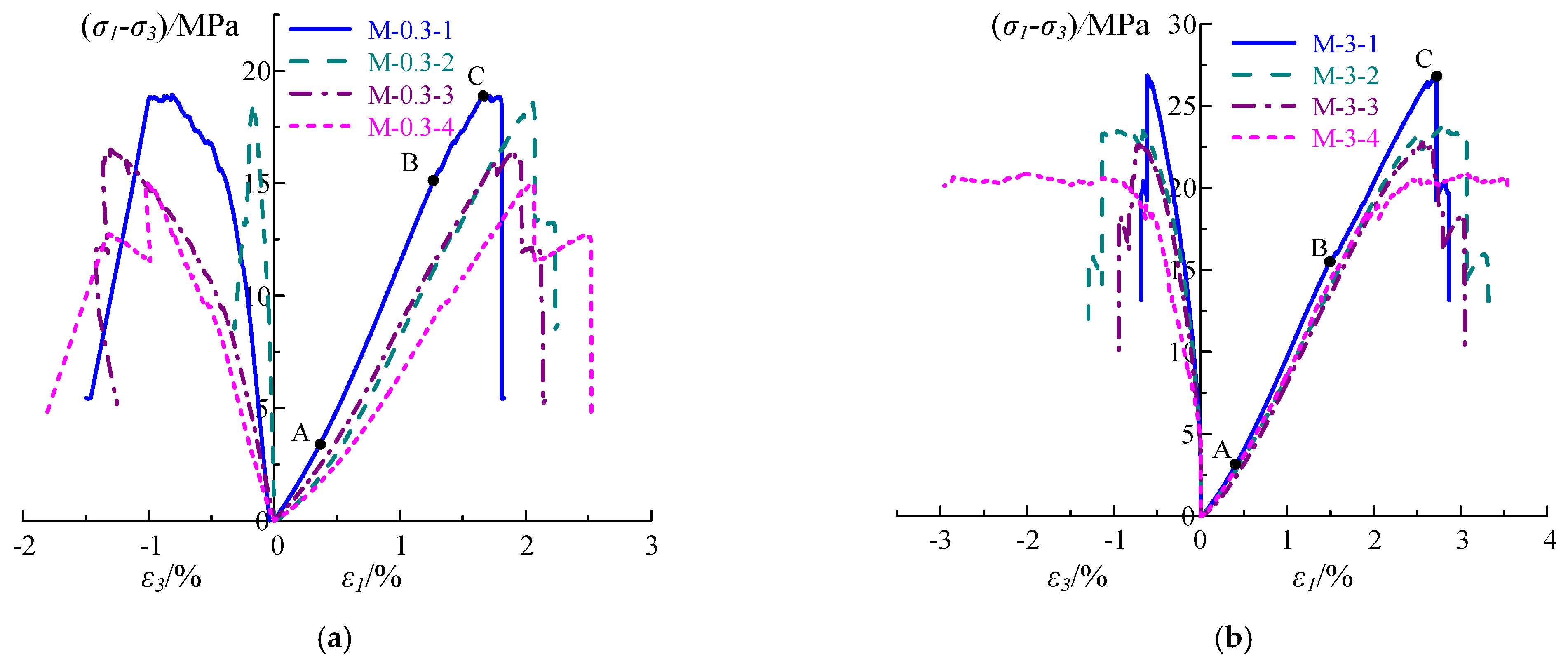
3.1. Stress–Strain Curve

Figure 4 shows the stress–strain curves of the fractured coal specimens under different confining pressures. It is indicated that the stress–strain curve of the fractured specimens can be divided into four stages: micro-fracture compaction (OA), elastic deformation (AB), unstable crack propagation (BC) and post-peak stage (after point C). As shown in Figure 4a, when the confining pressure is 0.3 MPa, the stress–strain curves of the fractured specimens are concave in the compaction stage of microcracks, and the strain increment decreases with the increase of the stress. The dominant reason for this phenomenon is that the primary microcracks existing in the specimens are closed driven by the external force. In the elastic deformation stage, the stress–strain curve of the fractured specimen changes approximately linearly, but the slope of the elastic deformation stage decreases gradually with the increase of the number of the prefabricated cracks. This is because the initial damage degree of the specimen increases gradually with the increase of prefabricated cracks, and the ability of specimen to resist deformation decreases gradually. In the stage of unstable crack development, the slope of the stress–strain curve of the fractured specimens decreases gradually, and yield characteristics can be observed. For specimen M-0.3-3, the stress–strain curve even has a small amplitude of stress drop. In the post-peak deformation failure stage, the stress of the fractured specimen decreases to a low level, and with the increase of the number of prefabricated cracks, the curve changes from a rapid drop to a stepped drop. As shown in Figure 4b, when the confining pressure is 3 MPa, the stress–strain curve is basically consistent with that of when the confining pressure is 0.3 MPa. However, with the increase of the number of prefabricated cracks, the slope of the elastic stage of the stress–strain curve has relatively small changes. The reason is that the increase of the confining pressure weakens the deformation ability of the specimen. The number of prefabricated cracks has a significant impact on the post-peak stage of the fractured specimens. When it is 1, the stress of coal specimens decreases rapidly to a low value. When it increases to 2, 3 and 4, the stress–strain curves all present a medium-range stress drop, and then the stress decreases to a low level, indicating that with the increase of the number of prefabricated cracks, the brittleness characteristics of the coal specimens are gradually weakened.

3.2. Changes in Mechanical Parameters

Figure 5 shows the variation curves of the basic mechanical parameters of the fractured coal specimens under different confining pressures. Figure 5 shows that with the increase of the number of the prefabricated cracks, the peak strength and elastic modulus decrease gradually. When the confining pressure is 0.3 MPa, with the increase of the number of prefabricated cracks, the peak strength of the coal specimens shows a trend of decrease. As the number of cracks increases from 1 to 2, 3 and 4, the peak strength decreases by 4.12%, 14.95% and 22.68%, respectively. This indicates that the strength damage becomes more obvious with the increase of the number of prefabricated cracks. As the number of cracks increases from 1 to 2, 3 and 4, the elastic modulus of coal specimens decreases by 11.23%, 16.06% and 28.11%, respectively. This indicates that with the increase of the number of prefabricated cracks, the deformation effect of the multiple prefabricated cracks is superimposed to a certain extent, resulting in the weakening of the deformation resistance of coal specimens, and thus the elastic modulus of coal specimens continues to decrease. The axial strain at the peak point has not shown obvious regularity with the increase of the number of prefabricated cracks. This is because with the increase of cracks, the specimen will produce a large deformation from the action of minor stress, but when the cracks reach a certain number, the specimen will be destroyed under minor stress conditions, so the axial strain decreases when the specimen is destroyed.

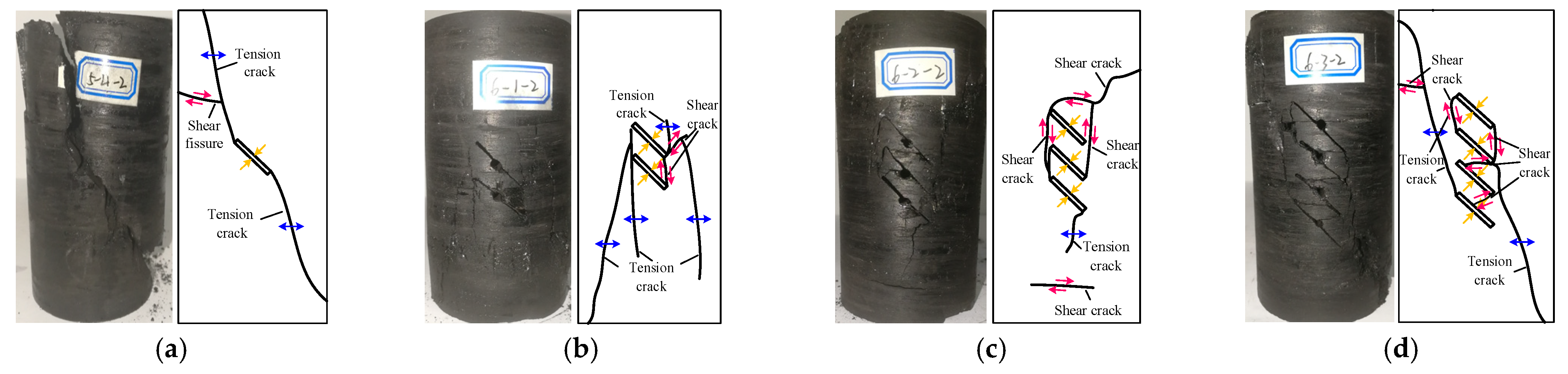
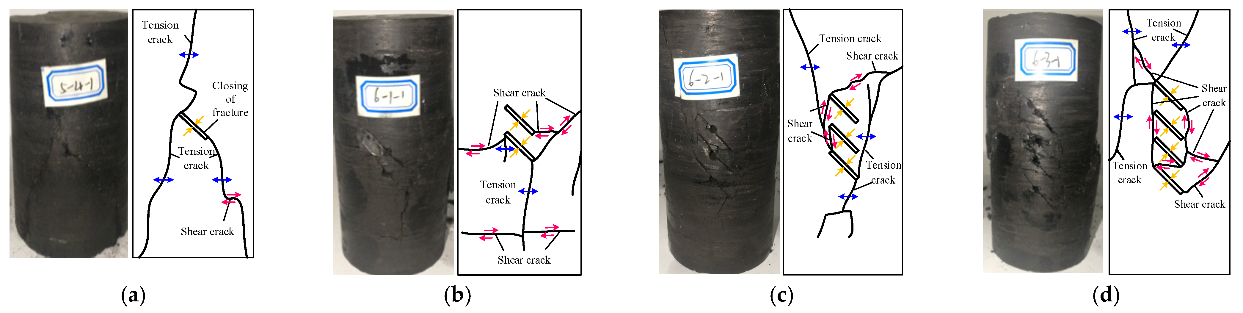
3.3. Failure Characteristics Analysis

Figure 6 shows the failure patterns and sketches of the fractured specimens under the confining pressure of 0.3 MPa. Compared with the intact specimen, as shown in Figure 2a, the intact specimen showed obvious tensile splitting failure under 0.3 MPa confining pressure. When the specimen contains prefabricated cracks, the following failure modes are exhibited: the failure of the single-fractured specimen is mainly induced by the tensile wing cracks that originate from both ends of the prefabricated crack and extend to the top and bottom of the specimen. This is a typical tensile failure mode. The failure of the double-fractured specimen is also mainly caused by the tensile wing cracks that start from the ends of the prefabricated cracks. The difference is that all the cracks extend only to the bottom of the specimen. Shear cracks connecting the prefabricated cracks are also generated. Such shear cracks play an even more important role in causing the failure of the three-fractured specimen. As shown in Figure 6c, these shear cracks are connected and thus reduce the bearing capacity of the specimen. Fewer tensile cracks are induced at the bottom of the prefabricated cracks and extend to the joint surface in the lower part of the specimen, resulting in a slight dislocation of the joint surface. As shown in Figure 6d, a larger number of shear cracks are produced near the prefabricated cracks in the four-fracture specimens. The tensile wing cracks emerging on both sides of the prefabricated cracks extend to both the top and bottom ends of the specimen, making it the dominant reason for the failure of the specimen.
Figure 7 shows the failure modes and sketches of the fractured specimens under the confining pressure of 3MPa. Compared with the intact specimen, as shown in Figure 2b, the intact specimen showed obvious shear failure under 3 MPa confining pressure. When the specimen contains prefabricated cracks, the following failure modes are exhibited: as shown in Figure 7a, the failure mode of this single-fractured specimen is similar to that shown in Figure 6a, except that tensile reverse wing cracks are also observed here. The failure of the double-fissure specimens is mainly caused by the shear cracks. The induced shear cracks originating from the left side of the prefabricated cracks and the tensile wing cracks from the right side both extend to the boundary of the specimen. A tensile crack penetrating the specimen passes through and twists the weak structural plane of the specimen. Therefore, the dominant and secondary causes of the failure of the specimen are shear crack and tensile fracture, respectively. As shown in Figure 7c, the failure of the three-fractured specimen resulted from a combination of tensile secondary cracks, tensile wing cracks and shear cracks. The tensile secondary cracks and the tensile wing cracks generated by the prefabricated cracks expand to the top and bottom of the specimen and undermine the bearing capacity of the specimen. The shear cracks are mostly located near the prefabricated cracks. When pressure is loaded, the ‘coal pillar’ will be damaged by the shear cracks, which results in the closure of the prefabricated cracks. The distribution of the cracks in the four-fissure specimen is even more complex. As shown in Figure 7d, there are many tensile cracks in the upper half of the specimen and several of them extend to the top and left sides of the specimen. There are also many shear cracks near the prefabricated cracks, leading to dislocation torsion in the lower half of the specimen. However, the cracks do not completely penetrate from top to bottom, indicating that the specimen has not failed completely and still has some extent of bearing capacity. This is consistent with the stress–strain curve, which shows that the specimen still has a certain strength in the post-peak stage.
Based on the above comparison of the failure modes under two confining pressures, we can conclude the following rules for the failure modes of the prefabricated-cracks specimen. When there is only one prefabricated crack, the tensile cracks that are developed around the prefabricated crack and run through the top and bottom ends of the specimen are the major reason for the failure of the specimen. When the number of the prefabricated cracks increases to 2, 3 and 4, the specimens are actually cut into small pillars by the prefabricated cracks. The fracture of the pillars leads to shear cracks near them, and tensile cracks are also produced by the axial stress at the distance of the cracks. Therefore, these specimens conform to the tensile-shear mixed failure mode. However, due to the existence of prefabricated cracks, the failure modes of cracked specimens are quite different from those of intact specimens.

4. Fractal Dimension Characteristics of Destroyed Coal Specimens under Different Fracture Numbers

4.1. Fractal Theory

The fractal theory [31,32] is based on the similarity principle to insight into the fine structure hidden in the chaotic phenomenon. It provides a new methodology for people to understand the whole from the local and the infinite from the limited, and provides a new language and quantitative description for the laws found in different disciplines. The fractal theory is widely used in the field of rock engineering, which creates a new way to solve the problems in rock mechanics theory and engineering practice. The damage evolution process of rock materials is fractal and has good self-similarity. The fractal dimension characterizes the damage degree of the material. The larger the fractal dimension is, the more serious the material damage is. The fractal dimension basically plays the role of the material damage variable [33]. Yang et al. [34] believe that fractal dimension is an important factor to characterize jointed rock mass. Huang et al. [35] analyzed the characteristics of fracture fractal dimension after rock failure and established the relationship between fractal dimension and confining pressure.
Fractal dimension is a parameter of fractal geometry to quantitatively describe the characteristics of fractal sets and geometric complexity. Due to the complexity of fractal sets, there are many definitions of fractal dimension, such as Hausdorff dimension, box dimension, capacity dimension, et cetera. The box dimension is gradually becoming one of the main methods to calculate the fractal dimension because it can accurately and conveniently measure the fractal dimension of self-similar images [36]. The calculation of the box dimension is:
D = lim r l o g N F l o g r
where N (F) is the number of frames in the fractal dimension, F is the division scale and r is the side length of the frame.

4.2. Fractal Characteristic

After the test was completed, the coal specimens that had deformed and became damaged were removed from the pressure chamber. The heat shrink tube on the surface was removed, and the damaged coal specimens were processed and analyzed. First, a sketch the surface of the destroyed coal specimens was made, as shown in Figure 5 and Figure 6. Then the sketch image file was imported into a MATLAB binarization program that was developed to convert the fracture surface morphology image from a gray-level image to a binary image, and the logical data from the binarization process were converted into binary data. Finally, the binary data is inversed and converted into numerical data, and the inversed data is used for fractal calculation, as shown in Figure 8. The reason why it is required to be opposite is that the white area is 1 and the black area is 0 for the binary image. If the image feature is represented by a black curve, the final calculated fractal dimension of the background is not the fractal dimension of the curve we want. Figure 9 shows the grayscale image of the fracture surface of coal specimens and the reverse binary image.
Figure 10 shows the relationship between the log2N and log2r of coal specimens with different numbers of prefabricated cracks. The slope of the curve is the fractal dimension of the failure surface. As shown in Figure 10, the correlation coefficient of the fitted curve is greater than 0.98, indicating that coal specimens with different crack numbers have obvious fractal dimension characteristics [37,38,39].
Figure 11 presents the relationship between fractal dimension and crack number. As shown in Figure 8, when the confining pressure is 0.3 MPa, the fractal dimension increases from 1.14 to 1.18 with the increase of prefabricated crack number. When the confining pressure is 3MPa, the fractal dimension increases from 1.15 to 1.20 with an increasing prefabricated crack number, indicating that the damage degree increases with the increase of crack number, which is consistent with the macroscopic failure results. It is found that a strong linear correlation is observed when the fractal dimension is correlated with the prefabricated crack number. This is because the increase of the number of prefabricated cracks leads to the increase of the initial damage of coal specimens, which leads to the aggravation of the damage degree, and is similar to the findings of Huang et al. [35]. Because the fractal dimension is a parameter used to characterize the degree of order and disorder of a nonlinear system, as the fractal dimension increases, the system’s degree of disorder increases. Therefore, it can be considered that with the increase of the number of prefabricated cracks, the disorder degree of coal specimen damage tends to increase.
The fractal dimension also shows an increasing trend with the increase of confining pressure, which may be related to the reinforcement effect of confining pressure. The strength of coal specimens increases as the confining pressure increases, which indicated that more energy will be released and more macroscopic fractures may be formed. This rule is consistent with the change law of fractal dimension.

5. Evolution Characteristics of Triaxial Strain Energy

5.1. Principle of Energy Analysis

In the process of deformation and failure of the rock under load, there is typically the input, accumulation, dissipation and release of energy. In this process, the strain energy can be divided into three types: total strain energy U, elastic strain energy Ue and dissipation energy Ud. The dissipative energy can generate surface energy and plastic energy of the fracture surface, resulting in rock damage and strength reduction. The instantaneous release of the elastic strain energy is an important factor causing sudden failure of the rock.
U = U e + U d
Figure 12 shows the relationship between the internal dissipation energy and the elastic strain energy of the rock during loading test. In the figure, Uid is the dissipated energy, which represents the energy consumed in the process of rock damage and failure, mainly including plastic deformation, friction and other activities. The shadow area of Uie represents the released strain energy stored in the rock. Ei is the unloading elastic modulus.
Generally, the elastic energy is calculated with the loading-unloading stress–strain curve, and the unloading modulus is replaced by the initial elastic modulus to simplify the calculation of elastic energy Ue. The calculation formula of elastic strain energy in the loading process is [40]:
U e = 1 2 E 0 σ 1 2 + 2 σ 3 2 2 v σ 3 2 + 2 σ 1 σ 3
where E0 is the initial elastic modulus and v is Poisson’s ratio.
In the triaxial tests, the external working force of the coal specimen includes the axial stress and the confining pressure of the testing machine. The axial stress works on the specimen and produces axial deformation. The confining pressure causes circumferential deformation [41]. Therefore, the total energy U absorbed by the specimen includes the axial strain energy U1 absorbed by the axial deformation and the circumferential strain energy U3 generated by the circumferential deformation:
U = U 1 + U 3
For any time t during the loading test, the absorbed axial strain energy and the circumferential strain energy with confining pressure as negative work consumption can be obtained by integrating the stress–strain curve [42]:
U 1 = 0 ε 1 ( t ) σ 1 d ε 1 = t = 0 t 0 1 2 σ 1 ( t + 1 ) + σ 1 ( t ) ε 1 ( t + 1 ) + ε 1 ( t )
U 3 = 2 0 ε 3 ( t ) σ 3 d ε 3 = t = 0 t 0 σ 3 ( t + 1 ) + σ 3 ( t ) ε 3 ( t + 1 ) + ε 3 ( t )

5.2. Effect of the Fracture Number Based on Energy Analysis

Figure 13 and Figure 14 show the energy evolution law inside the fractured coal body when the confining pressure is 0.3 MPa and 3 MPa, respectively. Similar trends can be observed from the energy evolution curves of specimens with different numbers of prefabricated cracks. The total energy of the prefabricated specimens increases with the increase of axial strain, with a low increasing rate in the early stage and a high rate in the later. In the compaction stage and elastic stage, the growth process of the elastic strain energy is consistent with the growth of the total energy, and there is little numerical difference. After reaching the peak stress point, the energy release is gradually reduced. This is because there is no obvious crack in the specimen before and during the elastic stage, the input energy is thereby almost completely transformed into elastic strain energy. With the gradual compaction of the internal openings in the specimen, the growth rate of elastic strain energy increases gradually. Then with the continuous loading of axial pressure, the internal cracks begin to sprout and expand, and the dissipation energy begins to increase rapidly. In the post-peak stage, the elastic strain energy stored in the specimen is released rapidly, and the crack propagation is accelerated. With the sharp decrease of the elastic strain energy, the dissipation energy increases significantly. Moreover, with the increase of the number of prefabricated cracks, the more obvious the ‘step’ drop state of elastic strain energy appears after the peak, the larger the corresponding strain range of ‘step’ is.
Table 2 shows the total energy, elastic energy, dissipation energy and dissipation energy ratio of the fractured coal specimens under peak stress. As shown in Table 2, when the confining pressure is fixed, with the increase of the number of prefabricated cracks, the peak total energy and elastic energy show a trend of gradual decreasing. For example, with a confining pressure of 0.3 MPa, when the number of prefabricated cracks increases from 1 to 4, the total energy decreases by 9.59%, and the elastic energy decreases by 17.51%. With a confining pressure of 3 MPa, when the number of prefabricated cracks increases from 1 to 4, the dissipation energy increases by 6.43%, and the dissipation energy ratio increases from 13.53% to 21.10%. With the increase in the number of fractures, the elastic energy stored in the coal specimen decreases gradually, and the proportion of dissipated energy and dissipated energy increases gradually. This indicates an increase of energy that is consumed for developing internal cracks, and a gradual decrease of the energy to be released when the specimen fails. As a result, the failure of the coal body tends to be smoother, which corresponds to the weakening of the brittle characteristics of the fractured coal body.

6. Conclusions

(1)
The stress–strain curve of the fractured coal specimens can be divided into four stages: the micro-fracture compaction stage, the elastic deformation stage, the unstable crack propagation stage and the post-peak stage. With the increase of the number of prefabricated cracks, the post-peak stage curve changes from rapid drop to step-down drop, indicating that with the increase of the number of prefabricated cracks, the brittleness of coal specimens decrease gradually. With the increase in the number of prefabricated cracks, the elastic modulus and peak strength decrease gradually. The failure mode of coal specimen changed from overall tensile failure to tensile-shear mixed failure.
(2)
The fractal dimension of coal failure with different number of prefabricated cracks is calculated by the box-counting method. The results show that the failure pattern of fractured coal specimens has obvious fractal dimension characteristics. With the increase of the number of prefabricated cracks, the fractal dimension of fractured coal specimens increases linearly, which indicates that the failure degree increases with the increase of the number of prefabricated cracks. With the increase of confining pressure, the fractal dimension also increases.
(3)
When the confining pressure is fixed, with the increase of the number of the prefabricated cracks, the peak total energy and elastic energy of fractured coal specimens decrease gradually. At the peak, the proportion of dissipation energy and dissipation energy increased gradually. It is indicated that with the increase of the development energy of internal cracks in coal, the failure of coal will be smoother as a result of the decrease of brittle characteristics of the coal.
(4)
Hydraulic slotting technology can enhance the drainage effect of gas and adjust the stress distribution of the coal body. As an uneven geological body, coal seams contain abundant primary cracks. After hydraulic slotting, cracks were initiated and developed around the slots under the action of the stress field. According to the results of this study, with the increase of the number of cracks, the failure mode of coal sample changes from brittle failure to ductile failure. Therefore, cracks can be set to reduce brittle failure and prevent dynamic disasters such as rock burst.

Author Contributions

Writing—original draft preparation, Z.W.; writing—review and editing, X.G. (Xufei Gong); data curation, X.G. (Xuebin Gu). All authors have read and agreed to the published version of the manuscript.

Funding

The research was funded by the Shandong Provincial Natural Science Foundation (No. ZR2019BD063) and Shandong Provincial Natural Science Foundation (NO. ZR2020QE135).

Institutional Review Board Statement

Not applicable.

Informed Consent Statement

Not applicable.

Data Availability Statement

Not applicable.

Acknowledgments

The authors acknowledge the Shandong Provincial Natural Science Foundation and the State Key Laboratory of Water Resource Protection and Utilization in Coal Mining). We also would like to express our sincere gratitude to Yongqiang Zhao, Chengfu Ma, Yanhui Deng and Yurong Li for their valuable comments, which have greatly improved this paper.

Conflicts of Interest

All authors declare that they have no conflicts of interest.

References

  1. Luo, F.; Diao, Y.; Wu, D.; Xu, P.; Guo, Y.; Li, M. Investigation on the macro-meso shear damage mechanical behaviors of fractured rocks. Chin. J. Rock Mech. Eng. 2022, 52, 301–314. [Google Scholar]
  2. Zhao, T.B.; Guo, W.Y.; Tan, Y.L.; Yin, Y.C.; Cai, L.S.; Pan, J.F. Case studies of rock bursts under complicated geological conditions during multi-seam mining at a depth of 800 m. Rock Mech. Rock Eng. 2018, 51, 1539–1564. [Google Scholar] [CrossRef]
  3. Zheng, J.; Guo, J.; Wang, J.; Sun, H.; Deng, J.; Lv, Q. A universal elliptical disc (UED) model to represent natural rock fractures. Int. J. Min. Sci. Technol. 2021, 32, 261–270. [Google Scholar] [CrossRef]
  4. Zuo, J.P.; Wei, X.; Shi, Y.; Liu, C.; Li, M.; Wong, R.H. Experimental study of the ultrasonic and mechanical properties of a naturally fractured limestone. Int. J. Rock Mech. Min. Sci. 2020, 125, 104164. [Google Scholar] [CrossRef]
  5. Ban, L.; Du, W.; Jin, T.; Qi, C.; Li, X. A roughness parameter considering joint material properties and peak shear strength model for rock joints. Int. J. Min. Sci. Technol. 2021, 31, 413–420. [Google Scholar] [CrossRef]
  6. Chen, W.Z.; Wang, L.Y.; Tan, X.J.; Yang, D.S.; Yuan, J.Q.; Yang, J.P. State-of-the-art and development tendency of the underground engineering stability of fractured rock mass. Chin. J. Rock Mech. Eng. 2021, 40, 1945–1961. [Google Scholar]
  7. Zhao, T.B.; Xing, M.L.; Guo, W.Y.; Wang, C.W.; Wang, B. Anchoring effect and energy-absorbing support mechanism of large deformation bolt. J. Cent. South Univ. 2021, 28, 572–581. [Google Scholar] [CrossRef]
  8. Tian, J.J.; Xu, D.J.; Liu, T.H. An experimental investigation of the fracturing behavior of rock-like materials containing two V-shaped parallelogram flaws. Int. J. Min. Sci. Technol. 2020, 30, 777–783. [Google Scholar] [CrossRef]
  9. Chen, L.X.; Guo, W.Y.; Zhang, D.X.; Zhao, T.B. Experimental study on the influence of prefabricated fissure size on the directional propagation law of rock type-I crack. International. J. Rock Mech. Min. Sci. 2022, 160, 105274. [Google Scholar] [CrossRef]
  10. Zong, Y.; Han, L.; Meng, Q.; Wang, Y. Strength properties and evolution laws of cracked sandstone samples in re-loading tests. Int. J. Min. Sci. Technol. 2020, 30, 251–258. [Google Scholar] [CrossRef]
  11. Zhang, W.; Guo, W.Y.; Wang, Z.Q. Influence of lateral pressure on the mechanical behavior of different rock types under biaxial compression. J. Cent. South Univ. 2022, 2022, 1–10. [Google Scholar]
  12. Zhao, T.B.; Zhang, P.F.; Guo, W.Y.; Gong, X.F.; Wang, C.; Chen, Y. Controlling roof with potential rock burst risk through different pre-crack length: Mechanism and effect research. J. Cent. South Univ. 2022, 29, 3706–3719. [Google Scholar]
  13. Yang, S.Q.; Dai, Y.H.; Han, L.J.; He, Y.N.; Li, Y.S. Uniaxial compression experimental research on deformation and failure properties of brittle marble specimen with pre-existing fissures. Chin. J. Rock Mech. Eng. 2009, 28, 2391–2404. [Google Scholar]
  14. Wang, Y.L.; Tang, J.X.; Dai, Z.Y.; Yi, T.; Li, X.Y. Effect of fracture number and aperture on mechanical properties and failure modes of low-strength rock mass. J. China Coal Soc. 2018, 43, 3338–3347. [Google Scholar]
  15. Tang, S.C.; Feng, P.; Zhao, J.S. Uniaxial mechanical properties and failure mechanism of rock specimens containing cross fissures. Chin. J. Undergr. Space Eng. 2021, 17, 1376–1383+1407. [Google Scholar]
  16. Haijian, S.; Hongwen, J.; Honghui, Z.; Yingchao, W.A. Experimental study on the influence of longitudinal fissure on mechanics characteristic of sandstone. J. Min. Saf. Eng. 2014, 31, 644–649. [Google Scholar]
  17. Jiang, M.J.; Chen, H.; Zhang, N.; Fang, R. Distinct element numerical analysis of crack evolution in rocks containing pre-existing double flaw. Rock Soil Mech. 2014, 35, 3259–3268+3288. [Google Scholar]
  18. Li, P.; Cai, M.F. Energy evolution mechanism and failure criteria of jointed surrounding rock under uniaxial compression. J. Cent. South Univ. 2021, 28, 1857–1874. [Google Scholar] [CrossRef]
  19. Li, Z.; Tian, H.; Niu, Y.; Wang, E.; Zhang, X.; He, S.; Wang, F.; Zheng, A. Study on the acoustic and thermal response characteristics of coal samples with various prefabricated crack angles during loaded failure under uniaxial compression. J. Appl. Geophys. 2022, 200, 104618. [Google Scholar] [CrossRef]
  20. Ding, Z.W.; Li, X.F.; Huang, X.; Wang, M.B.; Tang, Q.B.; Jia, J.D. Feature extraction, recognition, and classification of acoustic emission waveform signal of coal rock sample under uniaxial compression. Int. J. Rock Mech. Min. Sci. 2022, 160, 105262. [Google Scholar] [CrossRef]
  21. Mao, R.; Fang, K.; Zhao, T.B.; Liu, N. Failure mechanism of rock with pre-existing surface crack under cone penetration test. Chin. J. Rock Mech. Eng. 2022, 41, 1183–1192. [Google Scholar]
  22. Hao, X.J.; Du, W.S.; Zhao, Y.X.; Sun, Z.; Zhang, Q.; Wang, S.; Qiao, H. Dynamic tensile behaviour and crack propagation of coal under coupled static-dynamic loading. Int. J. Min. Sci. Technol. 2020, 30, 659–668. [Google Scholar] [CrossRef]
  23. Xiao, P.; Li, D.Y.; Zhao, G.Y.; Zhu, Q.Q.; Liu, H.X.; Zhang, C.S. Mechanical properties and failure behavior of rock with different flaw inclinations under couple static and dynamic loads. J. Cent. South Univ. 2020, 27, 2945–2958. [Google Scholar] [CrossRef]
  24. Zhu, W.S.; Chen, W.Z.; Shen, J. Study on model test and fracture mechanics mechanism of flying geese crack propagation. Chin. J. Solid Mech. 1998, 4, 75–80. [Google Scholar]
  25. Huang, K.Z.; Lin, P.; Tang, C.A.; Chau, K.T. Mechanisms of crack coalescence of pre-existing flaws under biaxial compression. Chin. J. Rock Mech. Eng. 2002, 6, 808–816. [Google Scholar]
  26. Xu, H.; Qin, Y.P.; Wang, G.; Fan, C.; Wu, M.; Wang, R. Discrete element study on mesomechanical behavior of crack propagation in coal samples with two prefabricated fissures under biaxial compression. Powder Technol. 2020, 375, 42–59. [Google Scholar] [CrossRef]
  27. Yu, H.; Liu, S.W.; Jia, H.S. Mechanical response and energy dissipation mechanism of closed single fractured sandstone under different confining pressures. J. Min. Saf. Eng. 2020, 37, 385–393. [Google Scholar]
  28. Yang, S.Q.; Dong, J.P.; Yang, J.; Yang, Z.; Huang, Y.H. An experimental investigation of failure mechanical behavior in cylindrical granite specimens containing two non-coplanar open fissures under different confining pressures. J. Cent. South Univ. 2022, 29, 1578–1596. [Google Scholar] [CrossRef]
  29. Wang, H.; Ren, F.Q.; Liu, D.Q. Experimental investigation on the influence of triaxial stress on seepage characteristics of sandstone with single fissure. China Civ. Eng. J. 2022, 1–13. [Google Scholar] [CrossRef]
  30. Liu, Z.; Ma, C.; Wei, X.A.; Xie, W. Energy evolution and failure characteristics of single fissure carbonaceous shale under drying-wetting cycles. Rock Soil Mech. 2022, 43, 1761–1771. [Google Scholar]
  31. Turcotte, D.L. Fractal and fragmentation. J. Geophys. Res. 1986, 91, 1921–1926. [Google Scholar] [CrossRef]
  32. Turcotte, D.L.; Jiang, H.K.; Wu, Q. Crustal deformation and fractal. Transl. World Seismol. 1996, 1996, 1–8. [Google Scholar]
  33. Xie, H.P.; Gao, F. Fractal characteristics of damage evolution of rock materials. Chin. J. Rock Mech. Eng. 1991, 10, 74–82. [Google Scholar]
  34. Yang, L.L.; Xu, W.Y.; Meng, Q.X.; Wang, R.B. Investigation on jointed rock strength based on fractal theory. J. Cent. South Univ. 2017, 24, 1619–1626. [Google Scholar] [CrossRef]
  35. Huang, Z.; Gu, Q.; Wu, Y.; Wu, Y.; Li, S.; Zhao, K.; Zhang, R. Effects of confining pressure on acoustic emission and failure characteristics of sandstone. Int. J. Min. Sci. Technol. 2021, 31, 963–974. [Google Scholar] [CrossRef]
  36. Peng, R.D.; Xie, H.P.; Ju, Y. Computation method of fractal dimension for 2-D digital image. J. China Univ. Min. Technol. 2004, 33, 22–27. [Google Scholar]
  37. Peng, R.D.; Yang, Y.C.; Ju, Y.; Mao, L.; Yang, Y. Calculation of rock pore fractal dimension based on gray CT image. Chin. Sci. Bull. 2011, 56, 2256–2266. [Google Scholar] [CrossRef]
  38. Li, X.D.; Song, Y.B.; Zhang, G.R. Study on the fractal characteristics of rock in the prediction of rockburst. RSC Adv. 2017, 7, 43073–43082. [Google Scholar]
  39. Ma, T.R.; Ma, D.P.; Yang, Y.J. Fractal Characteristics of Coal and Sandstone Failure under Different Unloading Confining Pressure Tests. Adv. Mater. Sci. Eng. 2020, 2020, 2085492. [Google Scholar] [CrossRef] [Green Version]
  40. Xie, H.P.; Ju, Y.; Li, L.Y. Criteria for strength and structural failure of rocks based on energy dissipation and energy release principles. Chin. J. Rock Mech. Eng. 2005, 24, 3003–3010. [Google Scholar]
  41. Guo, W.Y.; Zhang, D.X.; Zhao, T.B.; Li, Y.; Zhao, Y.L.; Wang, C.; Wu, W. Influence of rock strength on the mechanical characteristics and energy evolution law of gypsum-rock combination specimen under cyclic loading-unloading condition. Int. J. Geomech. 2022, 22, 04022034. [Google Scholar] [CrossRef]
  42. Guo, H.J. Research on the Energy Evolution Laws of Surrounding Rock Unloading and the Rockburst Mechanism in solid Coal Roadway Excavation. Ph.D. Thesis, China University of Mining and Technology, Xuzhou, China, 2019. [Google Scholar]
Figure 1. Distribution characteristics of fractured coal specimens and prefabricated cracks.
Applsci 12 12422 g001
Figure 2. Complete coal specimen stress–strain curve. (a) Confining pressure 0.3 MPa; (b) confining pressure 3 MPa.
Applsci 12 12422 g002
Figure 3. Test system.
Applsci 12 12422 g003
Figure 4. Stress−strain curves of fractured coal specimens. (a) Confining pressure 0.3 MPa; (b) confining pressure 3 MPa.
Applsci 12 12422 g004
Figure 5. Variation curves of basic mechanical parameters of fractured coal specimens under different confining pressures. (a) Confining pressure 0.3 MPa; (b) confining pressure 3 MPa.
Applsci 12 12422 g005
Figure 6. A 0. 3 MPa confining pressure with different numbers of prefabricated cracks in coal specimen failure mode and its sketch. (a) M-0.3-1; (b) M-0.3-2; (c) M-0.3-3; (d) M-0.3-4.
Applsci 12 12422 g006
Figure 7. A 3 MPa confining pressure with different numbers of prefabricated cracks in coal specimen failure mode and its sketch. (a) M-3-1; (b) M-3-2; (c) M-3-3; (d) M-3-4.
Applsci 12 12422 g007
Figure 8. Digital image process of fracture plans.
Applsci 12 12422 g008
Figure 9. Grayscale images of the fracture surface of coal specimens and reverse binary images. (a) M-0.3-1; (b) M-0.3-2; (c) M-0.3-3; (d) M-0.3-4; (e) M-3-1; (f) M-3-2; (g) M-3-3; (h) M-3-4.
Applsci 12 12422 g009
Figure 10. The relationship between log2N and log2r of coal specimens under different numbers of prefabricated cracks. (a) Prefabricated crack number of 1; (b) prefabricated crack number of 2; (c) prefabricated crack number of 3; (d) prefabricated crack number of 4.
Applsci 12 12422 g010
Figure 11. Relationship between fractal dimension and crack number.
Applsci 12 12422 g011
Figure 12. Relationship between internal dissipation energy and elastic strain energy of rock mass.
Applsci 12 12422 g012
Figure 13. Energy evolution of coal specimens with different numbers of prefabricated cracks under confining pressure 0.3 MPa with axial strain. (a) Coal specimen M-0.3-1; (b) Coal specimen M-0.3-2; (c) Coal specimen M-0.3-3; (d) Coal specimen M-0.3-4.
Applsci 12 12422 g013
Figure 14. Energy evolution of coal specimens with different numbers of prefabricated cracks under confining pressure 3 MPa with axial strain. (a) Coal specimen M-3-1; (b) Coal specimen M-3-2; (c) Coal specimen M-3-3; (d) Coal specimen M-3-4.
Applsci 12 12422 g014aApplsci 12 12422 g014b
Table 1. Types and numbers of coal specimens.
Crack Number/StripConfining Pressure 0.3 MPaCoal Specimen NumberConfining Pressure 3 MPaCoal Specimen Number
0M-0.3M-0.3-0M-3M-3-0
1M-0.3-1M-3-1
2M-0.3-2M-3-2
3M-0.3-3M-3-3
4M-0.3-4M-3-4
Table 2. Energy statistics at peak point of prefabricated cracked coal specimen.
Confining Pressure/MPaCrack Number/StripTotal Energy/kJ·m−3Elastic Strain Energy/kJ·m−3Dissipated Energy/kJ·m−3The Proportion of Dissipation Energy/%
0.31151.765131.23720.52813.53
2150.147127.44922.69815.12
3149.422122.61626.80617.94
4137.214108.25728.95721.10
31347.797280.12567.67219.46
2285.442215.82669.61624.39
3247.890177.23170.65928.50
4212.963140.93872.02533.82
Publisher’s Note: MDPI stays neutral with regard to jurisdictional claims in published maps and institutional affiliations.

