
Experimental Study of the Vibration of the Spot Welding Gun at a Robotic Station


Abstract
:1. Introduction
- Specialized software to support programming (RobotWare Spot from ABB, KUKA. SpotTech from KUKA, Spot Tool from FANUC);
- DressPacks-channels protecting the wires, tailored in shape to the type of robot;
- Specialized HMIs for programmers and operators;
- Advanced controllers that allow direct communication with the welding machine controller;
- Automatic recalculation of the tool’s TCP after tip dressing.

- Multiple use of the measuring station reduces the cost of the proposed vibration reduction method-no need to purchase sensory elements for each robot to be optimized;
- No interference with the design and software of the existing production stand;
- Possibility to apply the stand to robots from different manufacturers and different generations of robot operating systems;
- Taking into account the harsh working conditions of industrial robots, if fixed sensing elements are used, there is a risk of deterioration of the conditions of realization of the production process.
2. Related Work
3. Materials and Methods
3.1. Virtual Station
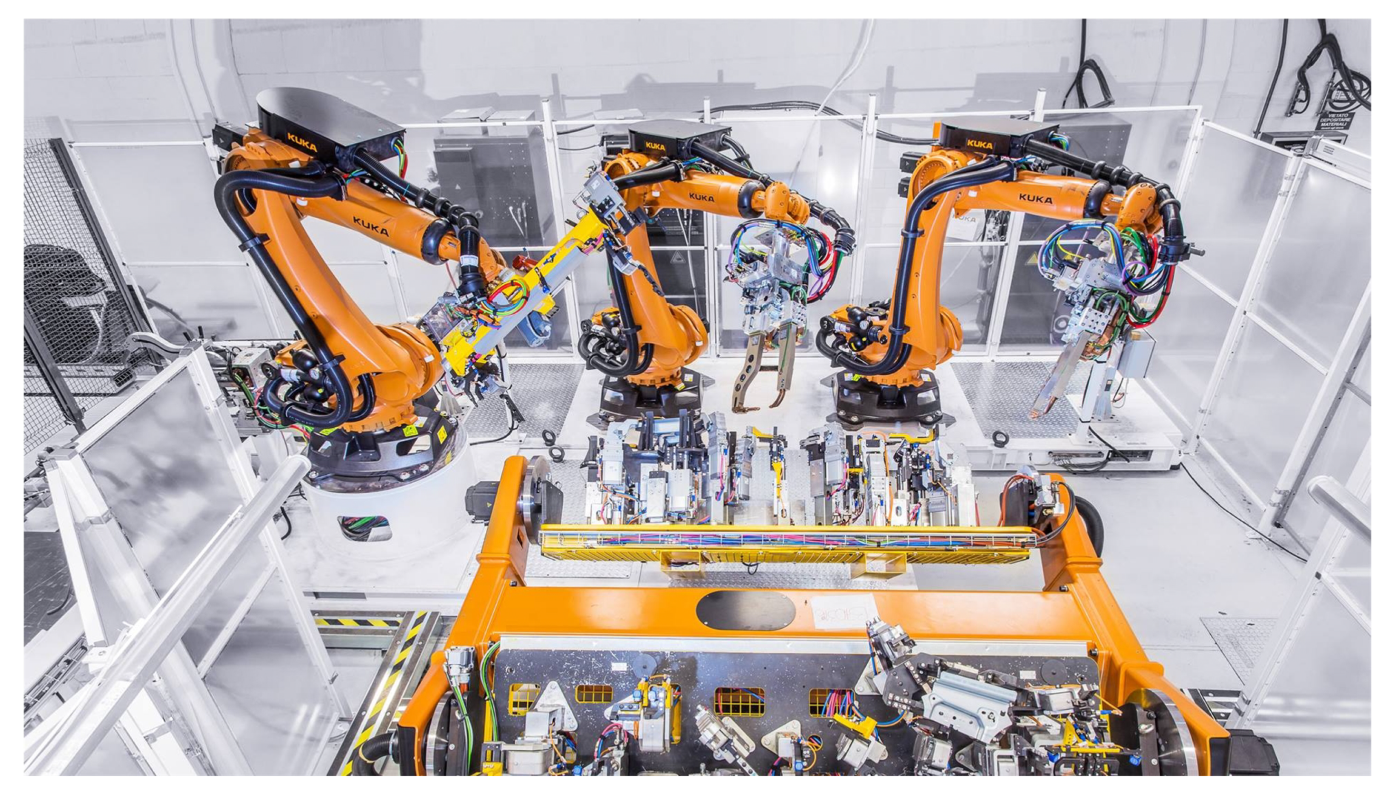
3.2. Test Stand
4. Tests
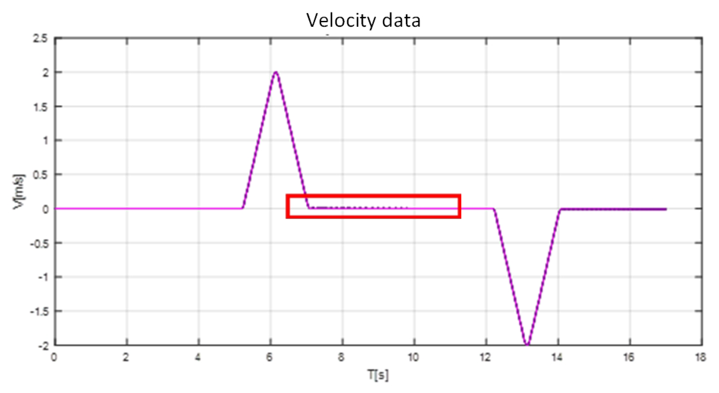
4.1. Results
- Creation of Matlab structure from imported data;
- Defining and picking a range of data for analysis;
- Minimizing the constant bias component through analysis of the silence period (before the robot actually starts moving).
4.2. Discussion
5. Conclusions
Author Contributions
Funding
Conflicts of Interest
References
- Bartoš, M.; Bulej, V.; Bohušík, M.; Stanček, J.; Ivanov, V.; Macek, P. An overview of robot applications in automotive industry. Transp. Res. Procedia 2021, 55, 837–844. [Google Scholar] [CrossRef]
- Chemweno, P.; Torn, R.J. Innovative robotization of manual manufacturing processes. Proc. Procedia Cirp 2022, 106, 96–101. [Google Scholar] [CrossRef]
- Lopes, T.C.; Sikora, C.; Molina, R.G.; Schibelbain, D.; Rodrigues, L.; Magatão, L. Balancing a robotic spot welding manufacturing line: An industrial case study. Eur. J. Oper. Res. 2017, 263, 1033–1048. [Google Scholar] [CrossRef]
- Banga, H.K.; Kalra, P.; Kumar, R.; Singh, S.; Pruncu, C.I. Optimization of the cycle time of robotics resistance spot welding for automotive applications. J. Adv. Manuf. Process. 2021, 3, e10084. [Google Scholar] [CrossRef]
- Kaczmarek, W.; Borys, S.; Panasiuk, J.; Siwek, M.; Prusaczyk, P. Experimental Study of the Vibrations of a Roller Shutter Gripper. Appl. Sci. 2022, 12, 9996. [Google Scholar] [CrossRef]
- KUKA. Automated Resistance Spot Welding with KUKA. Available online: https://www.kuka.com/en-de/industries/metal-industry/spot-welding (accessed on 24 October 2022).
- Batista, M.; Furlanetto, V.; Brandi, S.D. Development of a resistance spot welding process using additive manufacturing. Metals 2020, 10, 555. [Google Scholar] [CrossRef]
- Żółtowski, P.; Bużantowicz, W. Self-Balancing Power Amplifier with a Minimal DC Offset for Launcher Automation Control Circuits of a Surface-to-Air Missile System. Appl. Sci. 2022, 12, 3532. [Google Scholar] [CrossRef]
- Lisiecki, A.; Burdzik, R.; Siwiec, G.; Konieczny, L.; Warczek, J.; Folega, P.; Oleksiak, B. Disk laser welding of car body zinc coated steel sheets. Arch. Metall. Mater. 2015, 60, 2913–2922. [Google Scholar] [CrossRef] [Green Version]
- Pouranvari, M.; Marashi, S.P. Critical review of automotive steels spot welding: Process, structure and properties. Sci. Technol. Weld. Join. 2013, 18, 361–403. [Google Scholar] [CrossRef]
- Kaczmarek, W.; Panasiuk, J.; Borys, S.; Banach, P. Industrial robot control by means of gestures and voice commands in offline and online mode. Sensors 2020, 20, 6358. [Google Scholar] [CrossRef]
- Kaczmarek, W.; Lotys, B.; Borys, S.; Laskowski, D.; Lubkowski, P. Controlling an industrial robot using a graphic tablet in offline and online mode. Sensors 2021, 21, 2439. [Google Scholar] [CrossRef] [PubMed]
- Chen, Y.; Li, L.; Tang, W. An offline programming system for palletizing robot. Int. J. Adv. Robot. Syst. 2016, 13, 1–7. [Google Scholar] [CrossRef]
- Hsieh, Y.F.; Ye, J.H.; Wu, N.J.; Hsu, Q.C. Intelligent automatic deburring system by integrating palletizing robot with image and vibration sensors. Sensors Mater. 2021, 33, 933–945. [Google Scholar] [CrossRef]
- De Souza, J.P.C.; Amorim, A.M.; Rocha, L.F.; Pinto, V.H.; Moreira, A.P. Industrial robot programming by demonstration using stereoscopic vision and inertial sensing. Ind. Rob. 2022, 49, 96–107. [Google Scholar] [CrossRef]
- Zhu, L.; Gu, Z.; Shi, J.; Liu, W. Research on dynamic performance and motion control of robot manipulator. J. Vibroeng. 2015, 17, 3092–3103. [Google Scholar]
- Enescu, I. Performances and shapes of acceleration-deceleration curve of kinematical linkages. Int. J. Mech. 2020, 14, 125–129. [Google Scholar] [CrossRef]
- Xu, Y.P.; Hong, Y. Time optimal path planning of palletizing robot. Appl. Mech. Mater. 2014, 470, 658–662. [Google Scholar] [CrossRef]
- Shen, H.; Jiang, L.; Zhang, Q.; Tao, Y.; Cao, Y. A new method for high speed and smooth transfer of robot motion trajectory. Adv. Mech. Eng. 2016, 8, 1–9. [Google Scholar] [CrossRef] [Green Version]
- He, Y.; Mei, J.; Zang, J.; Xie, S.; Zhang, F. Multicriteria optimization design for end effector mounting bracket of a high speed and heavy load palletizing robot. Math. Probl. Eng. 2018, 2018, 6049635. [Google Scholar] [CrossRef] [Green Version]
- Guerra-Zubiaga, D.A.; Luong, K.Y. Energy consumption parameter analysis of industrial robots using design of experiment methodology. Int. J. Sustain. Eng. 2021, 14, 996–1005. [Google Scholar] [CrossRef]
- Stuhlenmiller, F.; Weyand, S.; Jungblut, J.; Schebek, L.; Clever, D.; Rinderknecht, S. Impact of cycle time and payload of an industrial robot on resource efficiency. Robotics 2021, 10, 33. [Google Scholar] [CrossRef]
- Borys, S.; Kaczmarek, W.; Laskowski, D. Selection and optimization of the parameters of the robotized packaging process of one type of product. Sensors 2020, 20, 5378. [Google Scholar] [CrossRef] [PubMed]
- Mishra, N.; Singh, S. Determination of modes of vibration for accurate modelling of the flexibility effects on dynamics of a two link flexible manipulator. Int. J. Non. Linear. Mech. 2022, 141, 103943. [Google Scholar] [CrossRef]
- Do, T.T.; Vu, V.H.; Liu, Z. Linearization of dynamic equations for vibration and modal analysis of flexible joint manipulators. Mech. Mach. Theory 2022, 167, 104516. [Google Scholar] [CrossRef]
- Shang, D.; Li, X.; Yin, M.; Li, F. Vibration Suppression Method Based on PI Fuzzy Controller Containing Disturbance Observe for Dual-flexible Manipulator with an Axially Translating Arm. Int. J. Control. Autom. Syst. 2022, 20, 1682–1694. [Google Scholar] [CrossRef]
- Shi, M.; Cheng, Y.; Rong, B.; Zhao, W.; Yao, Z.; Yu, C. Research on vibration suppression and trajectory tracking control strategy of a flexible link manipulator. Appl. Math. Model. 2022, 110, 78–98. [Google Scholar] [CrossRef]
- Valizadeh, A.; Shariatee, M. PZT Actuators’ Effect on Vibration Control of the PRRRP 2DOF Flexible Parallel Manipulator. Shock Vib. 2021, 2021, 6985661. [Google Scholar] [CrossRef]
- Huang, J.; Ji, J. Vibration control of coupled Duffing oscillators in flexible single-link manipulators. J. Vib. Control 2021, 27, 2058–2068. [Google Scholar] [CrossRef]
- Li, K.; Wang, H.; Liang, X.; Miao, Y. Visual Servoing of Flexible-Link Manipulators by Considering Vibration Suppression without Deformation Measurements. IEEE Trans. Cybern. 2021, 52, 12454–12463. [Google Scholar] [CrossRef]
- Meng, Q.; Lai, X.; Yan, Z.; Su, C.Y.; Wu, M. Motion Planning and Adaptive Neural Tracking Control of an Uncertain Two-Link Rigid–Flexible Manipulator With Vibration Amplitude Constraint. IEEE Trans. Neural Netw. Learn. Syst. 2022, 33, 3814–3828. [Google Scholar] [CrossRef]
- Ge, L.; Chen, J.; Li, R. Algorithm of palletizing robot vibration suppression based on the principle of optimal trajectory planning. In Proceedings of the 2017 29th Chinese Control In addition, Decision Conference (CCDC), Chongqing, China, 28–30 May 2017; pp. 92–96. [Google Scholar] [CrossRef]
- Berscheid, L.; Kroger, T. Jerk-limited Real-time Trajectory Generation with Arbitrary Target States. Proc. Robot. Sci. Syst. 2021. [Google Scholar] [CrossRef]
- Jalendra, C.; Rout, B.K.; Marathe, A. Vision sensor based residual vibration suppression strategy of non-deformable object for robot-assisted assembly operation with gripper flexibility. Ind. Rob. 2022, 49, 851–864. [Google Scholar] [CrossRef]
- Cooper, M.P.; Griffiths, C.A.; Andrzejewski, K.T.; Giannetti, C. Motion optimisation for improved cycle time and reduced vibration in robotic assembly of electronic components. AIMS Electron. Electr. Eng. 2019, 3, 274–289. [Google Scholar] [CrossRef]
- Ariano, A.; Perna, V.; Senatore, A.; Scatigno, R.; Nicolò, F.; Fazioli, F.; Avallone, G.; Pesce, S.; Gagliano, A. Simulation and experimental validation of novel trajectory planning strategy to reduce vibrations and improve productivity of robotic manipulator. Electronics 2020, 9, 581. [Google Scholar] [CrossRef] [Green Version]
- Fang, Y.; Hu, J.; Liu, W.; Shao, Q.; Qi, J.; Peng, Y. Smooth and time-optimal S-curve trajectory planning for automated robots and machines. Mech. Mach. Theory 2019, 137, 127–153. [Google Scholar] [CrossRef]
- Thomsen, D.K.; Søe-Knudsen, R.; Balling, O.; Zhang, X. Vibration control of industrial robot arms by multi-mode time-varying input shaping. Mech. Mach. Theory 2021, 155, 104072. [Google Scholar] [CrossRef]
- Yu, H.; Sun, Q.; Wang, C.; Zhao, Y. Frequency response analysis of heavy-load palletizing robot considering elastic deformation. Sci. Prog. 2020, 103, 0036850419893856. [Google Scholar] [CrossRef] [PubMed]


| Target | Target | Spotgun | Flange | Achieved | |
|---|---|---|---|---|---|
| No. | Velocity (V) | Acceleration (ACC) | Acceleration | Acceleration | Velocity |
| [mm/s] | [%] | [m/s] | [m/s] | [mm/s] | |
| 1 | 2000 | 100 | 0.220 | 0.171 | 2000 |
| 2 | 2000 | 75 | 0.111 | 0.099 | 1754 |
| 3 | 2000 | 50 | 0.107 | 0.111 | 1439 |
| 4 | 2000 | 25 | 0.092 | 0.102 | 1033 |
| 5 | 1500 | 100 | 0.214 | 0.207 | 1510 |
| 6 | 1500 | 75 | 0.166 | 0.096 | 1500 |
| 7 | 1500 | 50 | 0.114 | 0.135 | 1459 |
| 8 | 1500 | 25 | 0.128 | 0.098 | 1038 |
| 9 | 1000 | 100 | 0.155 | 0.161 | 1016 |
| 10 | 1000 | 75 | 0.159 | 0.151 | 993 |
| 11 | 1000 | 50 | 0.129 | 0.081 | 1012 |
| 12 | 1000 | 25 | 0.113 | 0.116 | 1002 |
| 13 | 500 | 100 | 0.211 | 0.225 | 520 |
Publisher’s Note: MDPI stays neutral with regard to jurisdictional claims in published maps and institutional affiliations. |
© 2022 by the authors. Licensee MDPI, Basel, Switzerland. This article is an open access article distributed under the terms and conditions of the Creative Commons Attribution (CC BY) license (https://creativecommons.org/licenses/by/4.0/).
Share and Cite
Borys, S.; Kaczmarek, W.; Laskowski, D.; Polak, R. Experimental Study of the Vibration of the Spot Welding Gun at a Robotic Station. Appl. Sci. 2022, 12, 12209. https://doi.org/10.3390/app122312209
Borys S, Kaczmarek W, Laskowski D, Polak R. Experimental Study of the Vibration of the Spot Welding Gun at a Robotic Station. Applied Sciences. 2022; 12(23):12209. https://doi.org/10.3390/app122312209
Chicago/Turabian StyleBorys, Szymon, Wojciech Kaczmarek, Dariusz Laskowski, and Rafał Polak. 2022. "Experimental Study of the Vibration of the Spot Welding Gun at a Robotic Station" Applied Sciences 12, no. 23: 12209. https://doi.org/10.3390/app122312209