1. Introduction
Constructal theory highlights the role of configuration in the survival of flow systems. It presents the generation of the architecture, and its evolution, as a universal physical phenomenon, in both natural and engineered systems [
1]. Following a different approach to developing engineering systems, Constructal Design includes the flow architecture as a design input instead of a result. Moreover, describing the flow architecture and assessing its evolutionary path implies linking its survival to greater efficiency and performance. Therefore, measuring the significance of the flow configuration requires a parameter to express it. Bejan and Lorente [
1] introduced a way to characterize a flow configuration by comparing an external length scale with an internal one, resulting in a global geometric property of the system designated as Svelteness (Sv).
According to Bejan [
2], the properties of a flow system include two global sizes, an external and an internal one; at least one global measure of performance; configuration; and freedom to morph. Svelteness is the parameter able to connect the flow system characteristics, emerging as a global property associated with the flow architecture and independent of the flow operating conditions and their type. When applied in Constructal Design, the results highlight its role in the overall performance and survival of flow systems and allow assessing the evolutionary direction of the flow configuration towards vascularization expressed through higher Sv values [
1,
2].
The application of Svelteness should be as broad as Constructal theory. However, its discussion remains restricted to applications regarding fluid flow, disregarding energy flows or any other type. According to Bejan and Errera [
3], configurations evolve toward the simplest form that still captures their meaning. For example, from one point to an area, flows evolve toward dendritic configurations visualized in the similarity between tree branches and river basins. Therefore, a higher Svelteness in a configuration indicates originality and a more effective way of conveying meaning.
In engineering applications, this meaning equals greater performance. Therefore, Constructal Design should guide engineers toward designing the flow architectures that, in time, continuously promote greater global performance.
After this Introductory Section, the next section synthesizes how researchers have considered Svelteness (Sv) as a design criterion, applying it in three main approaches to fluid flow configurations, namely a parallel flow [
4,
5,
6,
7,
8], the tree flow [
8,
9,
10,
11,
12,
13,
14,
15,
16,
17], and the radial tree flow [
18,
19,
20,
21]. In most research works, Sv is mentioned, but not explored or developed; instead, its role in the flow is assumed through criteria. However, some works explore Sv to assess its impact, and the following section reviews the reasoning underlying the use of the flow configuration of Svelteness as a design criterion. Afterward, in
Section 3, we review several examples exploring Svelteness as a design tool, followed by
Section 4, dedicated to the definition of the appropriate length scale with special emphasis on the external one. In this section, we use two configurations to suggest an essential criterion for choosing the external length scale. Finally, before the Conclusions, in
Section 5 of this review, for the aforementioned configurations, we explore the implications of a validated Svelteness as a design tool to assess the evolution of technological flow configurations.
2. Svelteness as a Design Criterion
In fluid flow, Svelteness has been used to show how the architecture of bifurcations impacts and relates to the pressure drop, showing how distributed losses dominate over local losses when Sv surpasses a certain threshold [
1,
10]. Although not explicitly declared, these results assume a value for the Svelteness and neglect local pressure losses over distributed losses in fluid flows. Higher values of Svelteness usually translate to better usage of the available space for minimizing the flow resistance while producing more complex flow architectures. However, complexity is a byproduct of Constructal Design, and its maximization is not a goal. In this sense, two main criteria are used in the literature for assessing Svelteness.
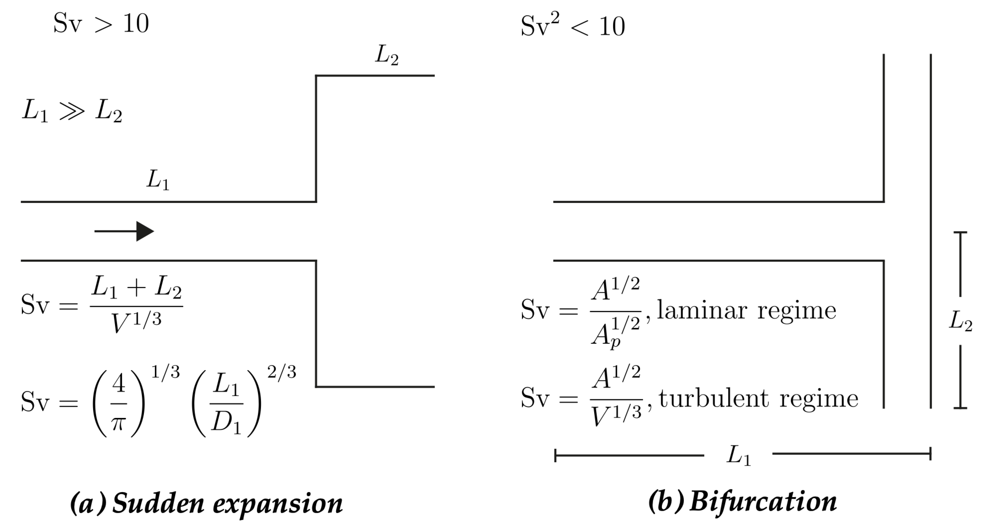
Bejan and Lorente [
1] introduced the first criterion using a sudden expansion in a pipe to demonstrate the effect of Sv on the relevance of local pressure losses relative to distributed friction losses (see
Figure 1a). The interpretation of the criterion, widely used in the literature, considers that
is enough to neglect local losses. This means the external length scale should be, at least, one order of magnitude larger than the internal length scale to validate this consideration:
. Although the criterion is bound to a precise geometry simplification, it is common to consider it a simplification with no correlation with the geometry of the scenario in which it was defined. However, the criterion defined by Bejan and Lorente [
1] is not strictly
, independently of the configuration, but a result of analyzing a sudden expansion, and using this value as universal can lead to a misuse of the criterion. Mistaking a value order by an order of magnitude can undermine the universal validity of such a criterion and should require further attention when used in Constructal Design, as shown in the following example.
In another approach, Wechsatol et al. [
21] investigated the effect of local losses on the optimized architecture of a T-shaped flow from a central point to a circular area of radius
R. What are the conditions, and how do local losses affect the optimized geometry? The authors’ approach to Svelteness (Sv) originates in Slenderness (Sl), an important factor for the friction effects and proportional to local losses. The Slenderness of a channel is the ratio between its length and diameter,
. Through normalization of both the length (
, with
R as the external length scale) and diameter (
, with
as the internal length scale), Wechsatol et al. [
21] considered Svelteness as:
Analyzing the T-shaped flow in laminar and turbulent conditions, with smooth and rough ducts for turbulent flow, Wechsatol et al. [
21] showed that the parametric domain that neglects junction losses is governed by Sv, and for domains where
, junction losses have an essential effect on the optimized geometry.
By analogy, the
criterion extends the initial version (
) to
, implying
, instead of 10. Still, the criterion does not consider its validity for a specific design. Both criteria (
or
) originate from the design intention that
, but one should assess its impact on the flow configuration. A reasonable threshold to assume local losses are irrelevant compared to distributed losses is to consider the former at least one order of magnitude smaller:
. The conservation of mass and momentum applied to the flow architecture allows relating the ratio between local and distributed head losses with Sv. Furthermore, once introduced in the criterion for the pressure drop ratio, Sv becomes the geometric manifestation and relation to the flow survival. At this point, designers can either have the freedom to choose the geometric features or let them act as constraints [
22]. The hypothesis explored in this work is that constraining geometric features to the flow survivability embodies Sv as a tool.
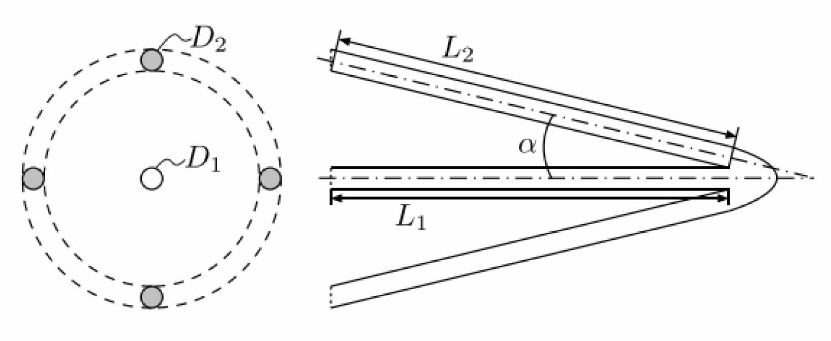
3. Svelteness as a Tool
Following the approach of Bejan and Lorente [
1], Clemente and Panão [
23] assessed the role of Sv in the configuration depicted in
Figure 2 of a central inlet channel and several outlets aimed at improving the cooling of a micro-mold insert.
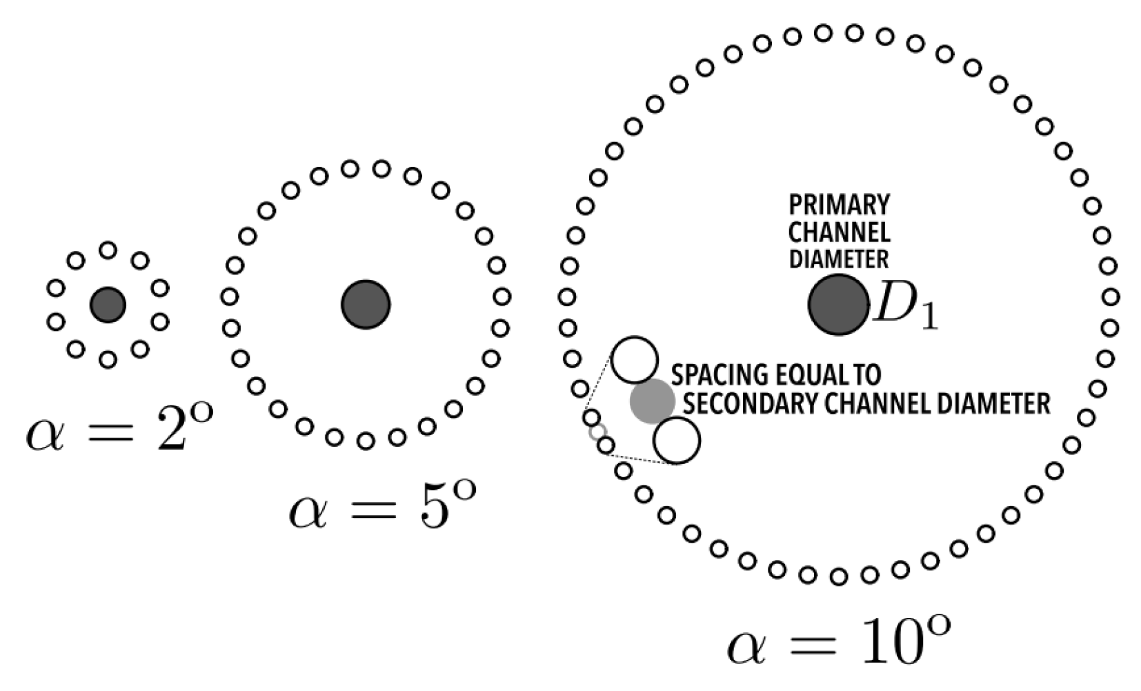
Figure 3 depicts the direction of flow evolution towards greater performance. In this work, the configuration designated as
umbrella had the following relation between the pressure loss ratio and a functional relation depending on Sv and Re:
where
and
are functions of the number of return channels (
n) and the angle between entry and return channels (
).
Applying the criterion considering local pressure losses, at most,
of distributed pressure losses due to friction,
Equation (
3), allows establishing a minimum Sv value that complies with the pressure loss criterion as:
Another example of such a relation is the study of the impact of Svelteness, the Reynolds number, and the bifurcation angle in the pressure drop of micro-channel tree branches by Ghaedamini et al. [
10]. The authors highlighted that flow and thermal distribution uniformity increase with Sv.
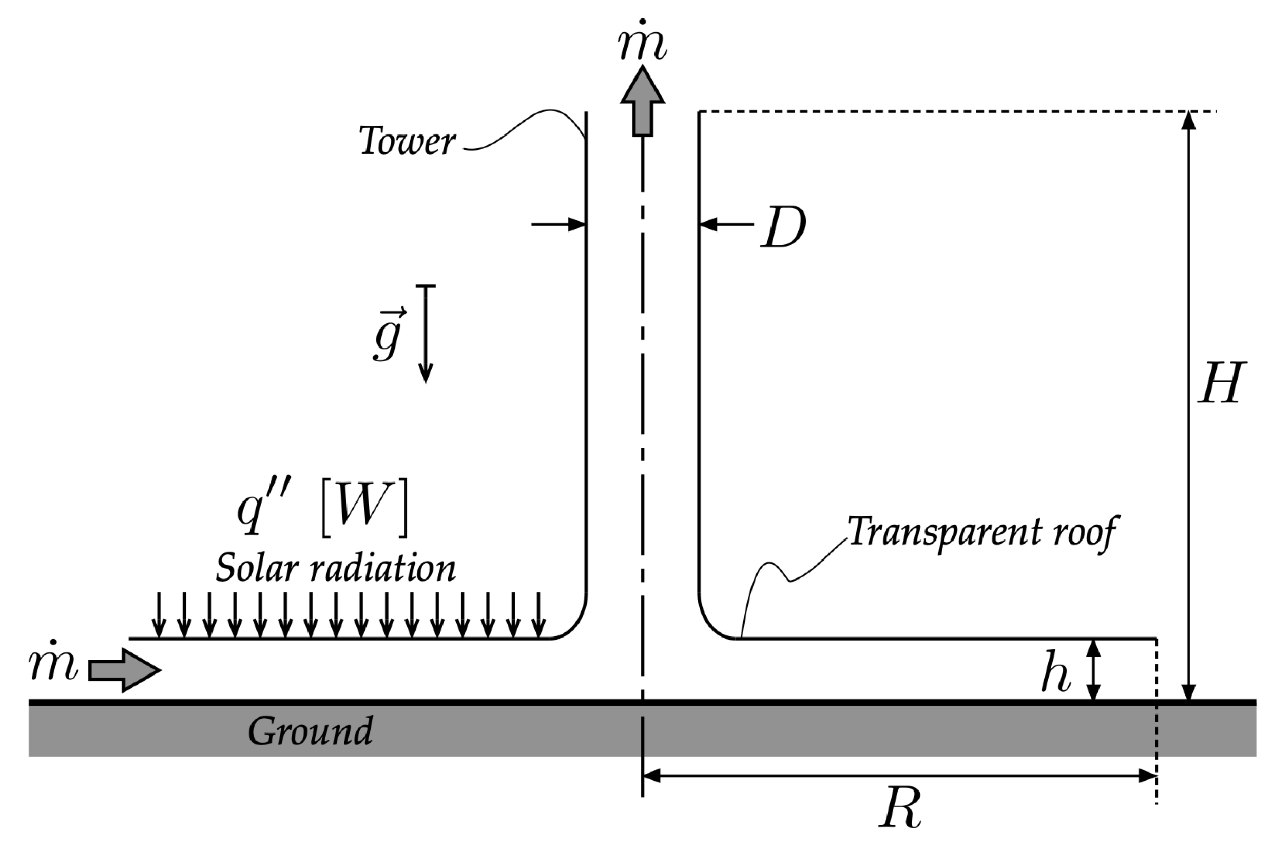
Koonsrisuk et al. [
24] showed that an appropriate configuration of a solar chimney would allow scaling the design. In this case, they introduced Svelteness to explore the effect of the solar chimney design on the significance of local losses and defined it as
where
H and
D are the tower height and diameter and
R and
h are the roof radius and height (see
Figure 4). The external length scale is the distance covered by the flow. In contrast, the internal length scale is the internal flow space of the system. In an analysis varying
H and
R from a reference solar chimney and comparing local pressure losses with friction losses induced by the acceleration of airflow inside the chimney, Koonsrisuk et al. [
24] concluded that local losses are negligible when
and that Sv decreases for larger roof radius
R.
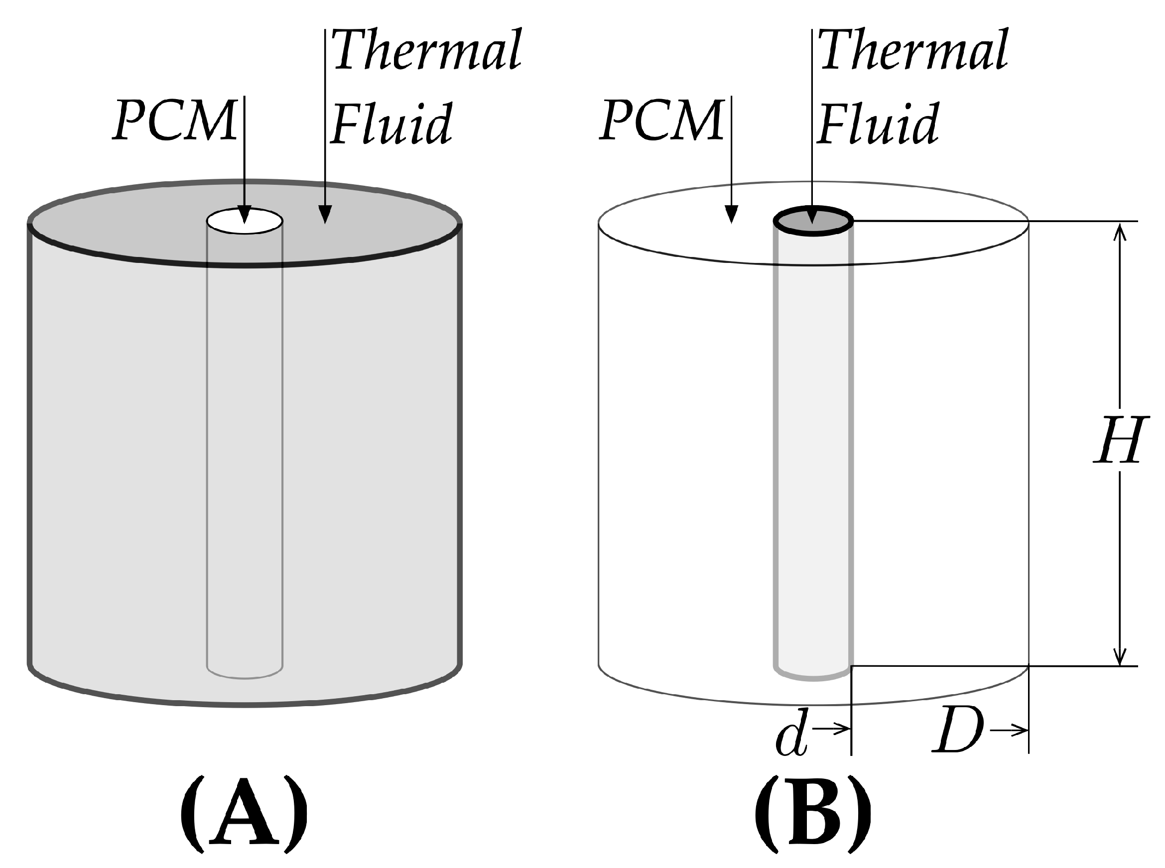
Since Sv guides the designer in the evolutionary direction of the flow configuration, comparing Sveltenesses allows for a helpful interpretation of the technological evolutionary direction of configurations. Panao [
25] illustrated this scenario by comparing a design with two different options for storing energy with a phase-change material in a storage tank with a vertical pipe (
Figure 5). The configurations alternate the location of the phase-change material and the thermal fluid, changing the direction of energy flow. Comparing the Sv of each case leads to the following relation:
where
D is the storage tank diameter,
d is the vertical pipe diameter, and
H is the storage tank length. The authors showed that the results match the geometry assumptions explored in the literature, explaining why other authors produced better results with their configurations through the evolutionary direction suggested by a larger Sv.
These examples illustrate the role of Sv in deciding the flow configuration and minimizing the impact of local pressure losses. They also emphasize the potential use of Sv as a design tool, relating geometric characteristics to the survival and performance of the flow, the generation of configurations, and as a factor to scale designs. Nonetheless, in most research, the definition of Sv is absent or merely stated, but not used to evaluate the evolutionary path of the flow configuration. Furthermore, while the internal length scale is clear and associated with the internal volume of what flows, a proper interpretation of the external length scale is lacking. For example, is the main path length enough, or should one consider the area covered by the configuration? Is this area fixed, and the configuration evolves in complexity, or is the area expanding as the flow configuration complexifies? The next section explores in greater depth the role of these length scales.
4. The Role of Length Scales
As previously defined, Sv is the ratio of internal and external length scales (Equation (
1)). Although the flow volume is well established as the ground for the internal length scale, there is still some divergence related to the external length scale.
The common use of Sv focuses on two definitions for the external length scale:
, the characteristic length occupied by an entire branch (Equation (
9a)); and
, based on the total area containing the flow configuration (Equation (
9b)). What are the implications of considering one versus the other, and what are their limitations?
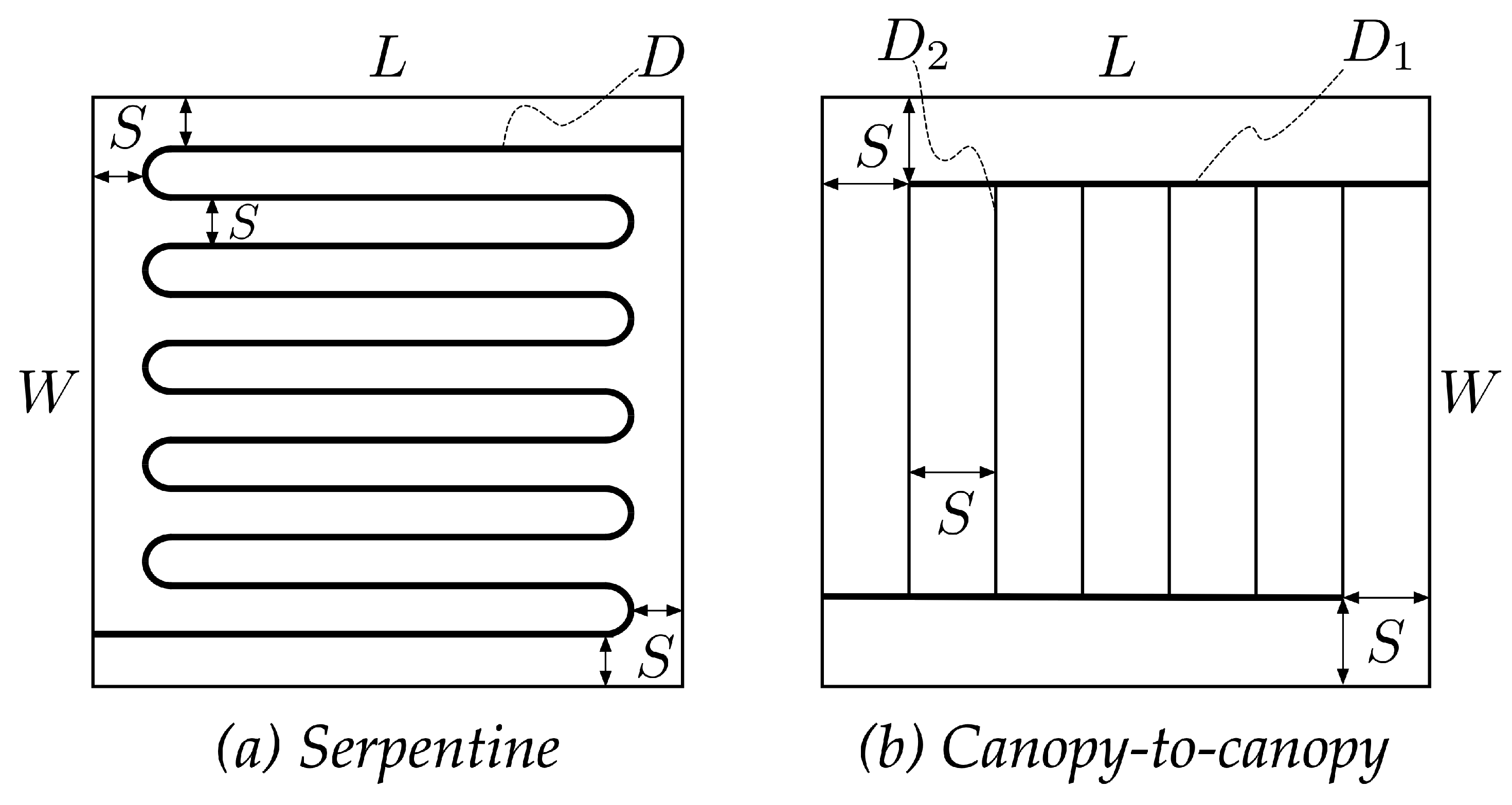
Consider two different architectures, serpentine (
Figure 6a) and canopy-to-canopy (
Figure 6b), where both layouts result in a set of parallel channels in a Z-type arrangement. The serpentine layout results from equally spaced U-turn channels, creating a set of horizontal parallel segments from bending a single tube of fixed diameter. The canopy-to-canopy layout consists of two horizontal manifolds interconnected with vertical parallel channels. Mosa et al. [
26] designed these two configurations in a set of different aspect ratios (
) with a fixed area and volume,
m
and
m
. The authors considered two types of canopy-to-canopy arrangements. One of them kept the tube diameter ratio (
) constant with
(
), and the other varied
(
); however, the focus will be on the latter.
Mosa et al. [
26] explored the application of the configurations on suspended radiant ceiling panels for cooling purposes. The authors assessed the performance by comparing the panel’s cooling capacity (
) to the pumping power required (
). Cooling capacity depends on the panel’s temperature distribution. Therefore, the best configuration should produce the most homogeneous temperature distribution. On the other hand, pumping power is affected by pressure losses. However, since the authors disregarded local losses compared to distributed losses, keeping the flow total length path small is advantageous. According to Mosa et al. [
26],
Figure 7 shows that parallel channels outperform serpentine one, with an optimum configuration for the aspect ratio of
with different diameters because this is the aspect ratio with the lowest flow resistance, as demonstrated in
Appendix A.
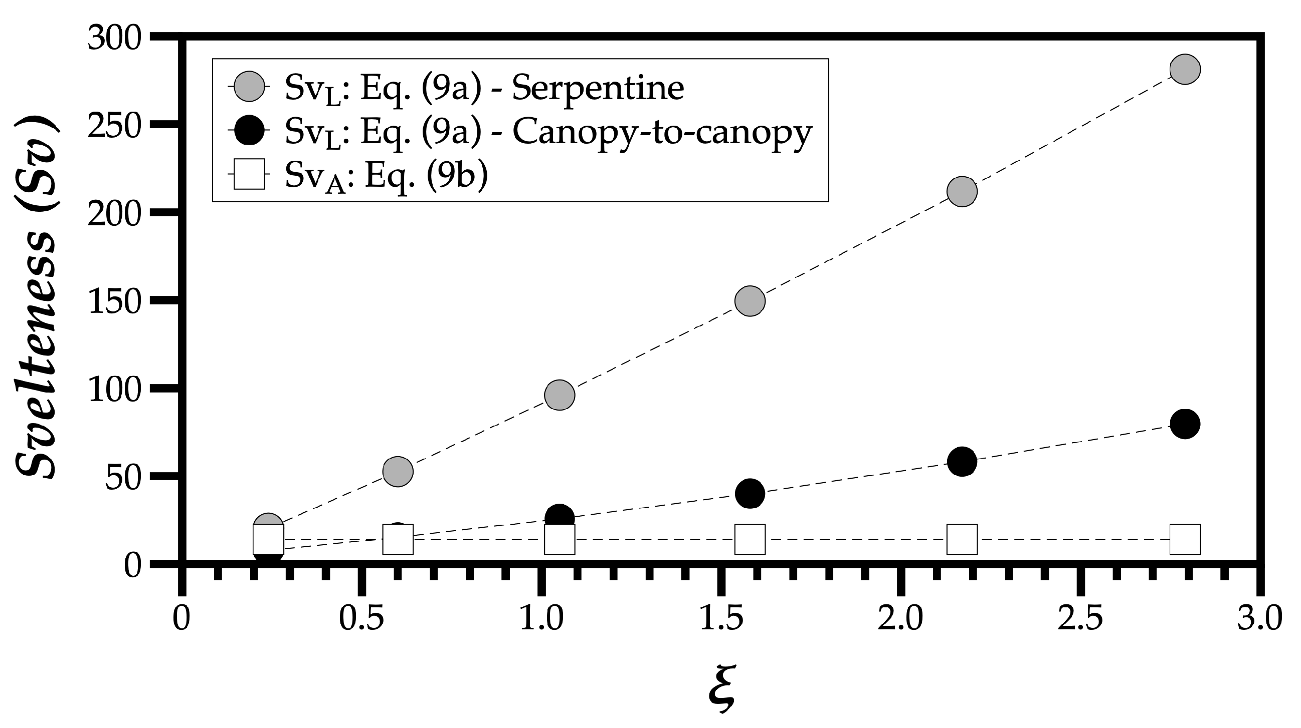
By analyzing Sv in these configurations according to Equations (
9a) and (
9b), we obtain a constant Sv for any case that uses the total area
A, and this makes any analysis of Sv pointless. The definition in Equation (
9a) seems the correct option, but defining
is not straightforward.
Furthermore, by restricting both the area and volume, we limit the freedom to morph the system to increase its complexity. In that setting, any configuration with a given volume in a given area will have the same Sv, thus eliminating any insight relating the evolution of flow architecture with the system’s performance.
Mosa et al. [
26] introduced a different setting for the external length scale, as
, i.e., the product between the flow path of the system and its aspect ratio. The flow path is the length from the inlet to the outlet, therefore directly related to the pressure drop.
For the serpentine configuration, if the number of tubes is
, from the lowest aspect ratio investigated by Mosa et al. [
26] to the highest value,
, with
, therefore, since
and
, the serpentine path is
and the canopy-to-canopy path length corresponds to
Figure 8 shows the results for Sv based on the total area according to Equation (
9b) and the value based on the approach of Mosa et al. [
26].
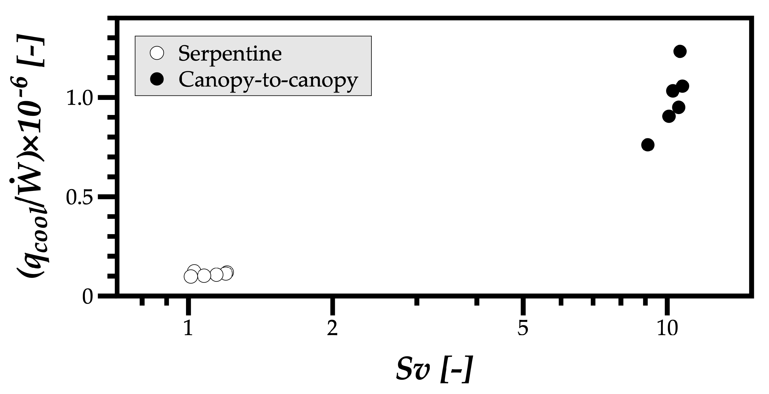
The serpentine configuration has the largest values of Sv, despite having the lowest performance (see
Figure 7), meaning there is no relation between the evolution of the flow configuration and the system’s performance unless one considers that the Sv based on the total area would be the appropriate definition. However,
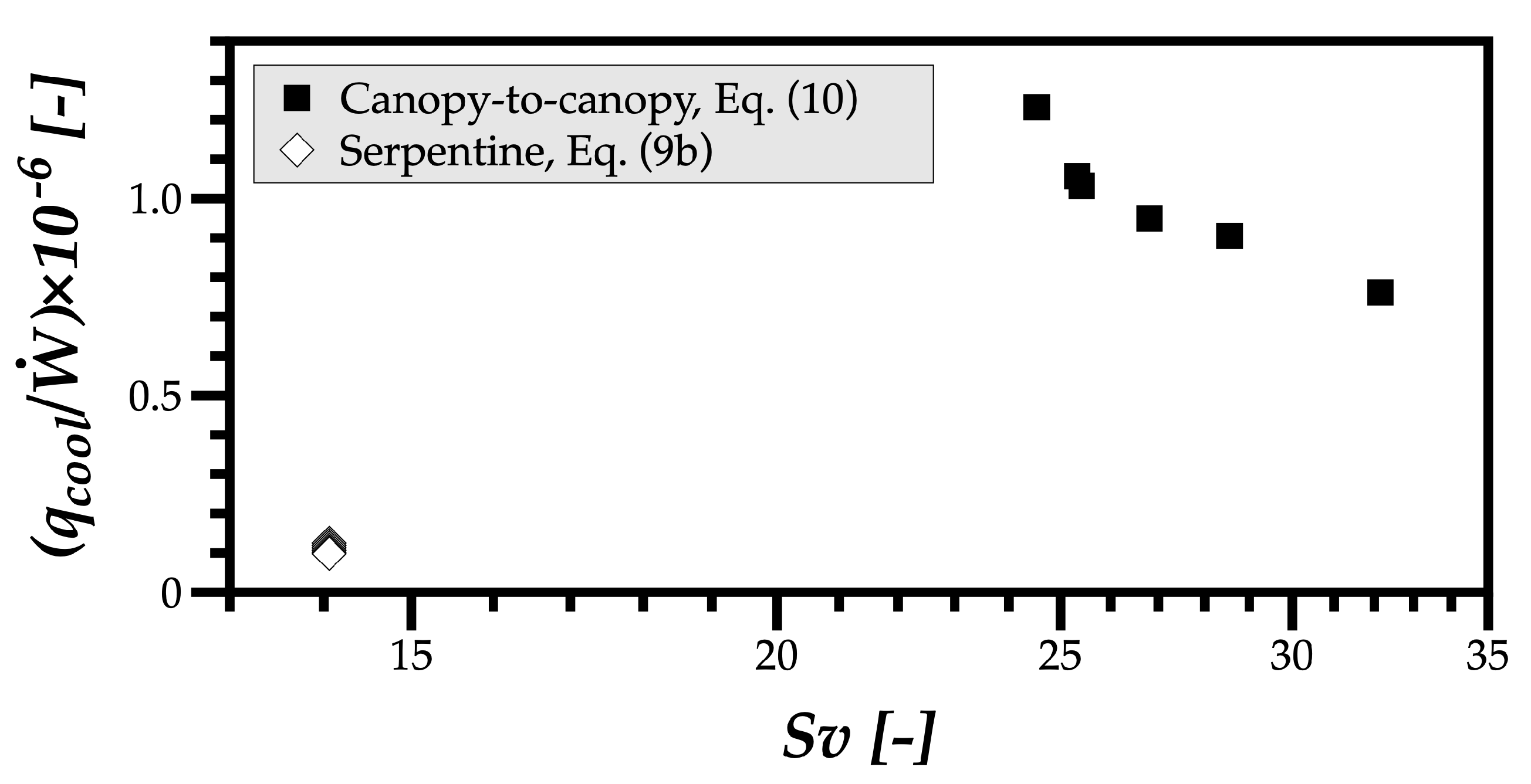
Figure 9 shows the canopy-to-canopy configuration’s performance degrades with Sv. Furthermore, despite the serpentine configuration’s performance being one order of magnitude lower than the canopy-to-canopy configuration’s performance, Sv has the same order of magnitude,
. These results do not make much sense and evidence the need for greater care in defining the appropriate external length scales, which is given in this review.
Clemente and Panão [
23] based the external length scale on the area occupied by a configuration with ramifications, not the total area accommodating the flow system. Moreover, without ramifications, as in the serpentine case, a single path occupies the configuration area defined in both cases (serpentine and canopy-to-canopy) as
. Therefore, our proposal distinguishes both cases:
Figure 10 shows the results with the new insight for the external length scale based on the existence or not of ramifications, and the Sv values are coherent with the performance reported for each configuration and aspect ratio variation. Namely, in the canopy-to-canopy configuration, a higher Sv indicates a higher performance, and the lower order of magnitude of the serpentine configuration’s performance corresponds to a Svelteness with a lower order of magnitude. These results validate the choices and reasoning behind the distinction between the definitions for the external length scale based on the existence of ramifications in the flow architecture.
After this validation, the final section before the Conclusions explores Svelteness as a design tool to show the evolutionary direction of the canopy-to-canopy configuration that has the highest performance.
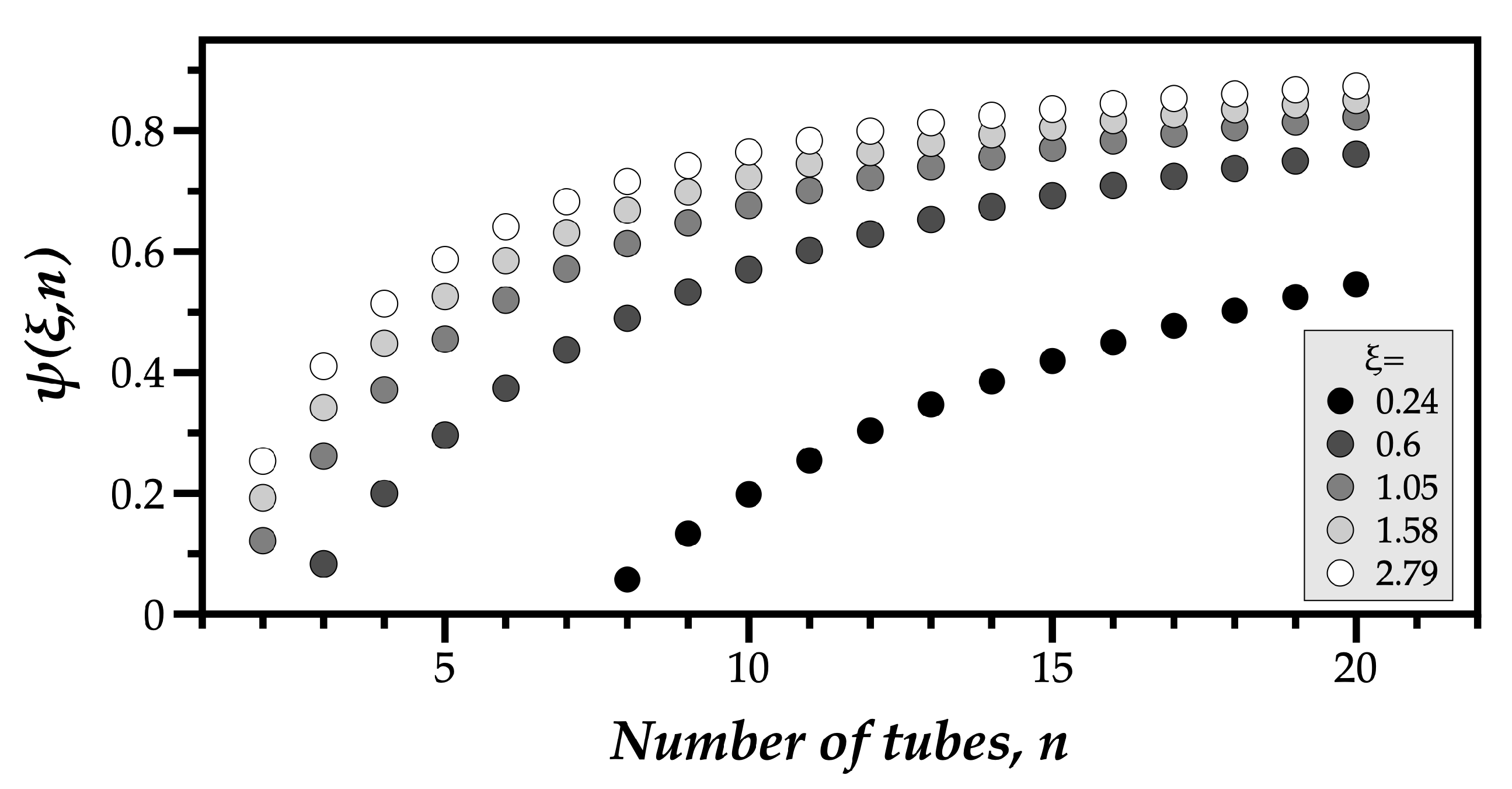
5. Exploring a Validated Svelteness
For the canopy-to-canopy configuration, the configuration area in terms of the input parameters corresponds to
which implies that
sets a minimum number of channels for each aspect ratio of
. Svelteness becomes
with
given by Equation (
9b), which is constant for the case under analysis of Mosa et al. [
26]. The evolutionary direction according to this Svelteness is higher aspect ratios with as many tubes as possible. However, the outcome is increasingly affected by diminishing returns controlled by
, as shown in
Figure 11 for the several aspect ratios considered by Mosa et al. [
26].
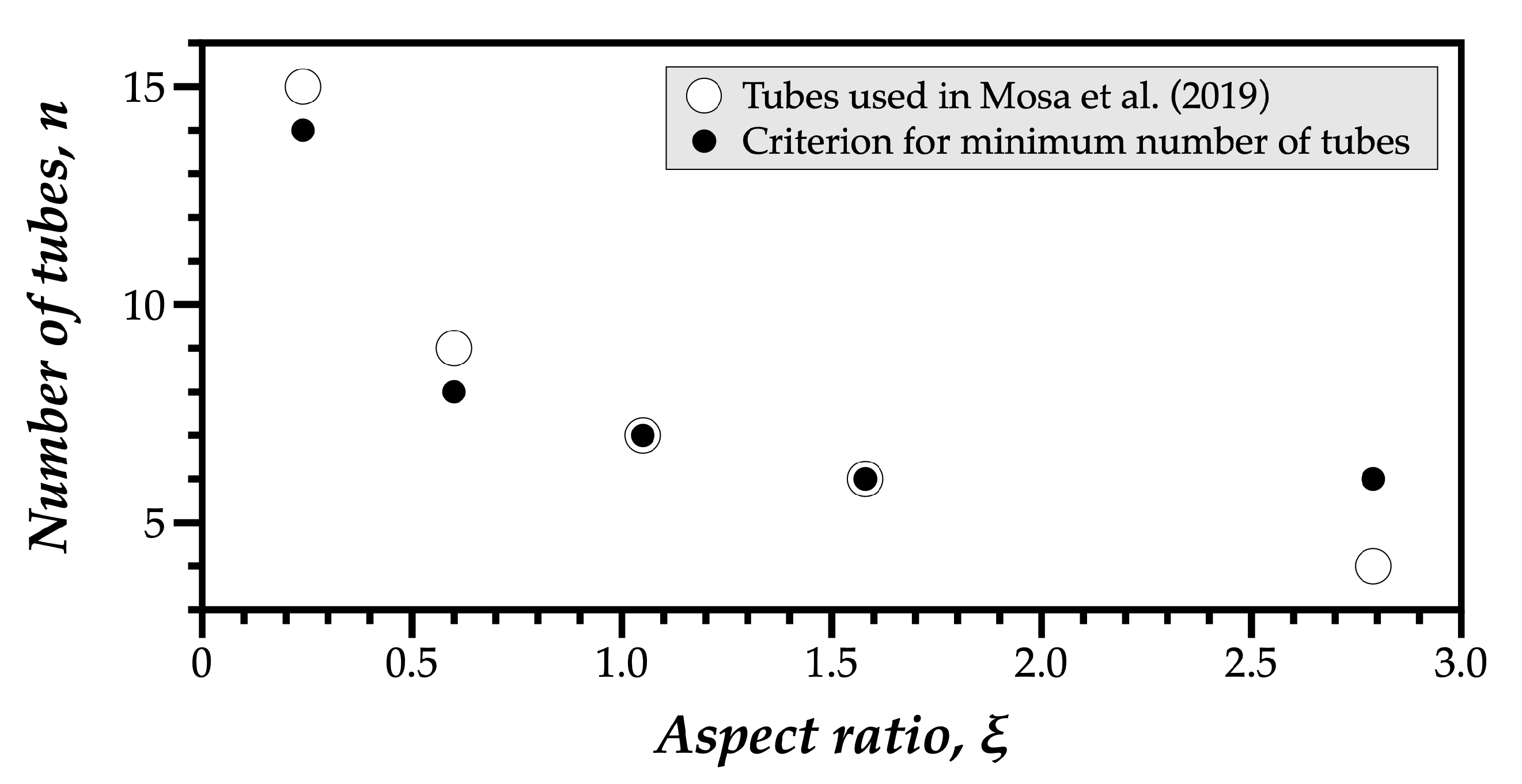
Therefore, to establish a criterion, we suggest applying the logarithm to
, which would correspond to the number of tubes needed to reach a certain level of growth in Svelteness.
The diminishing returns function would be
, and considering as the criterion a minimum number of tubes when
leads to the results shown in
Figure 12, which also includes the number of tubes used by Mosa et al. [
26].
For an aspect ratio of
, Mosa et al. [
26] used a number of channels lower than the value given by our criterion, but this was to keep the spacing between tubes equal to the remaining cases. In general, the minimum number of tubes ensuring the flow configuration as evolved is coherent with the number of tubes used in Mosa et al. [
26]. Above this number, one enters a region of diminishing returns, and more tubes do not mean a substantial increase in performance.
6. Conclusions
Constructal Design explores the introduction of configurations in an early stage of engineering development, providing an approach to accelerate and simplify design choices to reduce the effort of assessing a multitude of flow configurations.
The proposal of Svelteness as a measure to assess flow evolution stems from its particularity as a flow-independent parameter, but with the characteristics to evaluate it. While most approaches assume the role of Svelteness, its development as a foundation for applying Constructal Design explores the fundamental principles of flow survival.
This work sought to expand the application of Svelteness as a design tool, highlighting different use cases and exploring the formulation behind Svelteness, namely the challenges are in defining the external length scale (). However, using the results reported in the literature for the performance of the serpentine and canopy-to-canopy configurations, we suggest using the configuration area () when there are ramifications () and the relation between this area and the path length () in the configurations without ramifications (). Moreover, to establish a criterion to assess diminishing returns, we suggest using the logarithm to the part defining Svelteness, including all variable parameters, as an expression of the values these parameters need to have, above which Svelteness grows less than 10%. Finally, by developing relations between Svelteness and performance, the comparison and analysis of geometric parameters produce better insights when limiting the degrees of freedom in the analysis, leading designers closer to a better understanding of the technological direction of the flow evolution.


