1. Introduction
With the rapid development of information techniques and the accelerated evolution of industries, the cooperation and interoperation of remote systems are creating more complex systems, which are called systems of systems (SoSs) [
1,
2]. Due to their complexity, traditional system testing techniques are only efficient for constituent systems (CSs) but are no longer sufficient to verify SoSs. Simulation-based verification is heavily used for verifying complex systems and is widely employed for analyzing SoS models [
3,
4]. A set of input traces has to be selected to exercise the executable model of the SoS properly. The objective of test generation is to identify some input trajectories that can be used for simulation-based verification, assisting in identifying corner cases that expose model errors, thereby increasing the designer’s confidence in the model analysis. Several techniques for automatically generating test cases have been defined in the literature, starting from the implementation of a system or model by representing its requirements [
5,
6,
7]. Related methods and techniques for SoS verification are still in the preliminary research state, mainly for requirements verification and system verification. There is a lack of efforts in design verification for SoSs; currently, the test cases for design verification are mainly designed manually by SoS designers or architects. Aiming to provide the ability to detect hazardous states at the design phase, we worked on a novel method of automatically generating test cases for model verification in SoSs.
In this paper, we focus on model-based test generation, which uses a model-based representation to compose the requirements or functions of a system and SoS and automatically generate test cases for design verification. More precisely, we design an approach and a specific algorithm to extend the application of model-based fault-injection test-case generation to the case of an SoS. Fault-based test generation [
8] aims to produce a set of test cases that exercise the system under test to stress its fault tolerance. In the context of an SoS, we aim to apply fault-based test generation to identify possible sequences of behaviors that expose hazards at the SoS level. The obtained test cases represent the input for effectively testing the SoS behavior. The main objectives of the paper are to (1) propose an automatic test generation (ATG) approach adopting fault injection and model-based system engineering (MBSE); (2) design an ATG algorithm to support test cases generation; and (3) apply the proposed ATG method in an experimental SoS. The proposed ATG method provides the ability to detect hazardous states at the design phase, assisting design verification for SoS engineering.
2. Background
ATG for complex systems is a challenging research topic and several solutions have been proposed in the literature [
9,
10,
11]. In the context of SoSs, test generation is still an active research topic, and there are currently no standard methods and approaches that are widely used or have developed into the norm.
The technique of fault-based test generation is well-known in the context of system design. Some studies focused on improving accuracy and classification ability via fault diagnosis [
12,
13]; others applied related techniques on complex systems in various domains, such as agriculture [
14] and mechanical engineering [
15]. Fault-based test generation is complementary to the structural test generation that generates tests aiming at maximizing a coverage metric based on the syntactic structure of the model behavior specification. In the following subsections, we provide a brief overview of the application of fault injection techniques for verifying digital systems and service-oriented architecture (SOA).
2.1. Fault-Based Test Case Generation for Digital Systems
Digital systems were one of the early research areas studying and applying fault-based test generation. In [
16], the authors described a test generation method that combined architectural and gate-level techniques to achieve tests with a high fault coverage. In [
17], the tests generated from high-level descriptions using software test generation techniques were used as drivers for subsequent gate-level automatic test pattern generation processes reducing the effort and testing time. Corno et al. [
18] presented an automatic test-program generation for the testing of system-on-a-chip cores based on evolutionary algorithms aiming at obtaining a high fault coverage for design validation at the behavioral register-transfer level. In [
19], the authors described a method for generating tests starting from a VHDL model and using behavioral descriptions to describe the failure model. In [
20], a two-phase approach was described for minimal diagnostic test set generation. In [
21], Shi et al. described a genetic-algorithm-based approach to diagnose test generation, aiming to generate tests capable of diagnosing a single fault. In [
22], the application of integer linear programming techniques to select a representative set of test cases for diagnostic purposes was described.
Satisfiability (SAT) solvers have been extensively used as backend engines for automatic test pattern generation (ATPG) procedures. The papers [
23] and [
19] represented the initial stage of research efforts on converting ATPG to SAT problems. Yang et al. [
24] described a formal engine based on SAT-solving techniques for generating a minimal test set. In [
25], the authors provided an overview of recent advances in exploiting such techniques, introducing an incremental satisfiability-based mechanism. In [
26], a general overview of the strength and weaknesses of this technique was summarized, which pointed out two main challenges, including transformation overhead and efficiency. Among recent works, new SAT-based APTG processes were designed to face challenges via preprocessing [
27], incremental workflow [
28], and increased defect coverage [
29].
2.2. Fault Injection Test Generation for Service-Oriented Architectures
SOA is a set of loosely coupled, independent components called services that expose a well-defined interface and communicate exchanging messages [
30,
31]. In an SOA, the computation and resource access are performed using network infrastructures and service communications standards such as Web Services Description Language (WSDL) or Simple Object Access Protocol (SOAP). Each invoked service may not be aware of the internal status of other services, and it only exposes its interface, completely encapsulating the implementation aspects of the service. A Web service is a specific embodiment of an SOA service that uses the HTTP protocol and Web-related standards as backbone technologies for its invocation.
SOAs and Web services are already extensively used in e-commerce and e-banking applications and an even more pervasive adoption is envisioned in the future as a technological layer for the Internet of things [
32,
33]. Correctness, availability, and reliability are desired characteristics of an SOA and many approaches have been developed to ensure that a given set of services satisfy those requirements even in presence of faults [
31,
34]. Fault injection mechanisms are extensively exploited to ensure a safe composition of Web services even in the presence of failures. In [
35], the authors proposed a fault injection method for testing Web services based on data perturbation of the XML messages exchanged by the services. The data of the message could be modified according to the XML schema syntax, such as a data value perturbation, the modified message was sent to the Web service, and the response was then validated by the test framework. Additionally, to support the designed method, a tool named GenAutoWS was developed and implemented. In [
36], the authors described a fault injection framework for testing Web services’ fault-tolerance based on the emulation of a WAN network and the injection of network and application faults. Ghani et al. [
37] provided an overview of testing methods for Web services covering compile-time and run-time software fault injection mechanisms and tools and how to reuse the techniques in the context of the dependability assessment of Web services.
Considering the wide application of model-based system engineering (MBSE), a model-based test generation is beneficial to support constituent systems and to embed verification into the SoS life cycle, especially for design verification. Therefore, among the different existing ATG methods, the model-based fault injection test case generation for systems was adopted as the foundation of this research, and it can be described as follows steps: (i) an input model of the system under test is provided as input; (ii) the input is processed either manually or automatically and an enriched model is produced, identifying for each component a list of failure modes that affect it; (iii) a set of system-level ATG constraints conditions are identified and formalized directly in the model or using a tool-specific language; and (iv) the enhanced input model and the ATG constraints are processed by the engine searching for test cases leading to the violation of system-level hazards by the injection of faults. A set of test cases is produced as a result of the ATG process. Each test case contains a sequence of input values and fault injections that leads to the occurrence of a hazard condition. The test cases can be used to exercise a fault-tolerant implementation of the model or to reason on the model since each test case may expose possible flaws in the system design or specification.
The remainder of this paper is organized as follows.
Section 3 presents the proposed ATG method.
Section 4 provides the setup of the experiment, which is the modeling of a simplified emergency response SoS as the concept alignment example (CAE).
Section 5 discusses the experimental results of our study.
Section 6 summarizes our contributions.
3. Proposed Methodology
This research focuses on proposing a model-based test case generation method for the analysis of the effects of predictable faults on the SoS functionality at the design stage, containing an algorithm to enhance the automation ability in the process. Therefore, our primary objective was not to maximize a given coverage metric, but rather to identify the minimum number of independent events that could cause a hazardous state in the SoS to be reached.
In the context of an SoS, test case generation based on fault injection aims to increase stakeholders’ confidence in the SoS robustness from a quality assurance perspective. The generated test suites can be used to simulate the behavior of the SoS in the presence of a specific sequence of faults evaluating the correct capability of detecting and tolerating faults.
Evaluating the safety aspects of an SoS is of paramount importance due to the complex emergent and unexpected evolutions it may expose. In particular, an unsafe behavior may result as a consequence of the following SoS characteristics [
38,
39,
40]:
Evolutionary development: an initial design that is considered safe in a first development iteration can expose unsafe behaviors as a consequence of the addition of new services or the modification of existing functions in successive design iterations.
Operational and managerial independence: the integration of systems that are reliable and safe with respect to local hazard conditions can be unsafe from an SoS point of view due to the inherent independence of the CSs from both an operational and a managerial standpoint.
Emergent behavior: all potential unsafe behaviors should be detected and properly evaluated by the SoS designers. For an industrial SoS, it is difficult to avoid unsafe behaviors due to the loose coupling of the CSs and the evolutionary nature of their design. Hence, the identification of hazardous chain of events is fundamental to evaluating the safety of the entire SoS.
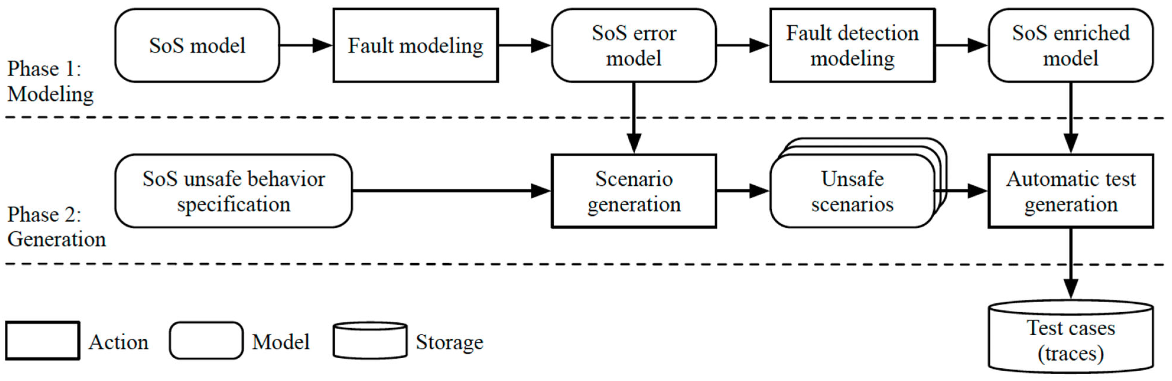
The SoS test generation methodology is summarized in
Figure 1. During the first phase, modeling, different models of the SoS are produced: (i) a first model of the SoS is produced using the Unified Profile for DoDAF and MODAF (UPDM) standard; (ii) a model of error behaviors is then specified (SoS error model), which contains a description of faults that can affect the CSs and the effects of the faults on their behavior (failure modes), but the detection and protection mechanisms are not modeled; and (iii) the error model is further elaborated including the fault detection and isolation (FDI) mechanisms as well as recovery procedures.
In the second phase, generation, three test generation scenarios are envisioned: (i) the error model is elaborated by a scenario generation that identifies how the SoS can evolve to a hazardous state specified as an external predicate by the user; (ii) the scenarios generated at the previous step are exploited to produce fault-injection-based test cases that can be used to exercise a fault-tolerant model of the SoS or as a driver for the effective robustness test of a new CS under development; and (iii) for each fault detection mechanism modeled as a monitor component, a specific fault injection test suite is produced automatically deriving the fault injections that enable the FDI process. The generation steps we designed are detailed in the following subsections.
3.1. Scenario Generation
The objective of the analysis is to generate acceptable executions that can reveal the evolution of the SoS from a safe to a hazardous state. These executions represent corner case scenarios that expose a possible hazardous evolution of the system that the designers should evaluate to compute the effective probability of occurrence of the generated hazardous event chain and design the safety control architecture of the SoS.
Formally, an SoS is modeled as a state transition system. A state transition system is a tuple where is a set of states (possibly infinite), is a subset of (initial states), and is the state transition relation that maps a state to a set of target states. A run of the transition system is a sequence of states starting from an initial state s.t. and hold.
The hazardous states are modeled as a linear temporal logic (LTL) formula where is a Boolean formula that encodes the hazardous states.
The scenario generation process produces a set of finite traces . Each generated trace satisfy the hazard LTL formula following the common semantics of the operator in the context of LTL logic.
Each generated trace reveals an executable scenario that leads to a hazard condition, which can be used further to diagnose the design flaws in the SoS models and operational hierarchy. The design flaws can be classified into three categories: (i) single design fault of an individual CS model or the interaction of multiple CSs; (ii) combination of design faults in CSs; (iii) unsafe SoS emergent behavior after CSs’ integration.
It is the responsibility of the ATG tool to generate a meaningful set of scenarios to identify such unsafe emergent behavior, enabling designers to reason about the SoS and how individual CSs impact the safety of other systems.
3.2. Automatic Test Generation
The ATG aims at identifying a set of traces each containing a sequence of SoS un-controllable and fault events that can be used to assess the fault tolerance of the SoS fault control model or a CS. The ATG can be performed using two complementary approaches, namely, the ATG for FDI or the ATG from generated scenarios.
The objective of the analysis is to produce a test suite that exercises the SoS fault detection mechanisms. The generated tests can be used to check the effectiveness of the FDI and for effective testing of CSs. The formalization of the problem is similar to the scenario generation and is summarized as follows.
The SoS model, containing both the nominal and the failure mode behaviors, is modeled as a state transition system . The FDI mechanism is modeled as a monitor component formally represented by a Boolean function over the state of the model that holds if the injected fault is detected. Similar to the scenario generation case, the ATG process efficiently enumerates all the runs of the transition systems s. t. .
Each generated trace identifies how it is possible to enable the detection of the FDI mechanism and it can be used to evaluate the effectiveness and correctness of the model as well as a driver for the testing of the CS.
The SoS unsafe emergent behaviors can be processed by the ATG, producing a set of test cases in which each stresses a subset of the fault identified in the scenario. More precisely, the generated scenario can be elaborated by producing a representation of the minimal cut set (MCS) considering the unsafe behavior as the top-level event. From an engineering perspective, a failure of any component in the MCS means the failure of the whole system. Hence, the MCS is then processed by generating a campaign of fault injections that can be then used to i) stress a fault-tolerant model of the SoS and ii) identify test scenarios for a CS that has to be integrated into the flow.
3.3. Automatic Test Generation Algorithm
In this section, we provide a description of our designed ATG algorithm at both high and low levels. In the high abstraction level, the inputs of the algorithm are as follows.
Model of the SoS formally capturing: (i) the SoS architecture (CSs, interfaces, data exchanged with their types, services exposed/required and related events, etc.); (ii) the behavior of each CS in terms of state machines; (iii) the events identifying external accidents or modeled faults for each CS; (iv) the ATG predicate over the formal elements of the model (events exchanged, states entered in state machines, etc.) that models the target of the ATG; and (v) additional assumptions on the CS or on the occurrences of the fault/accident events.
Automatic test generation algorithm’s parameter settings: (i) test case maximum length bound—the maximum admissible length for the test case; and (ii) test cases maximum number—the maximum number of test cases produced by the ATG.
The outputs of the ATG algorithms are:
A test report summarizing the results of the ATG process (number of generated test cases and for each test case, its length, and the number of faults injected).
A test suite collecting the test cases as an XML file reporting for each case the sequence of occurrences of the accidental and fault events leading to the satisfaction of the hazard predicate.
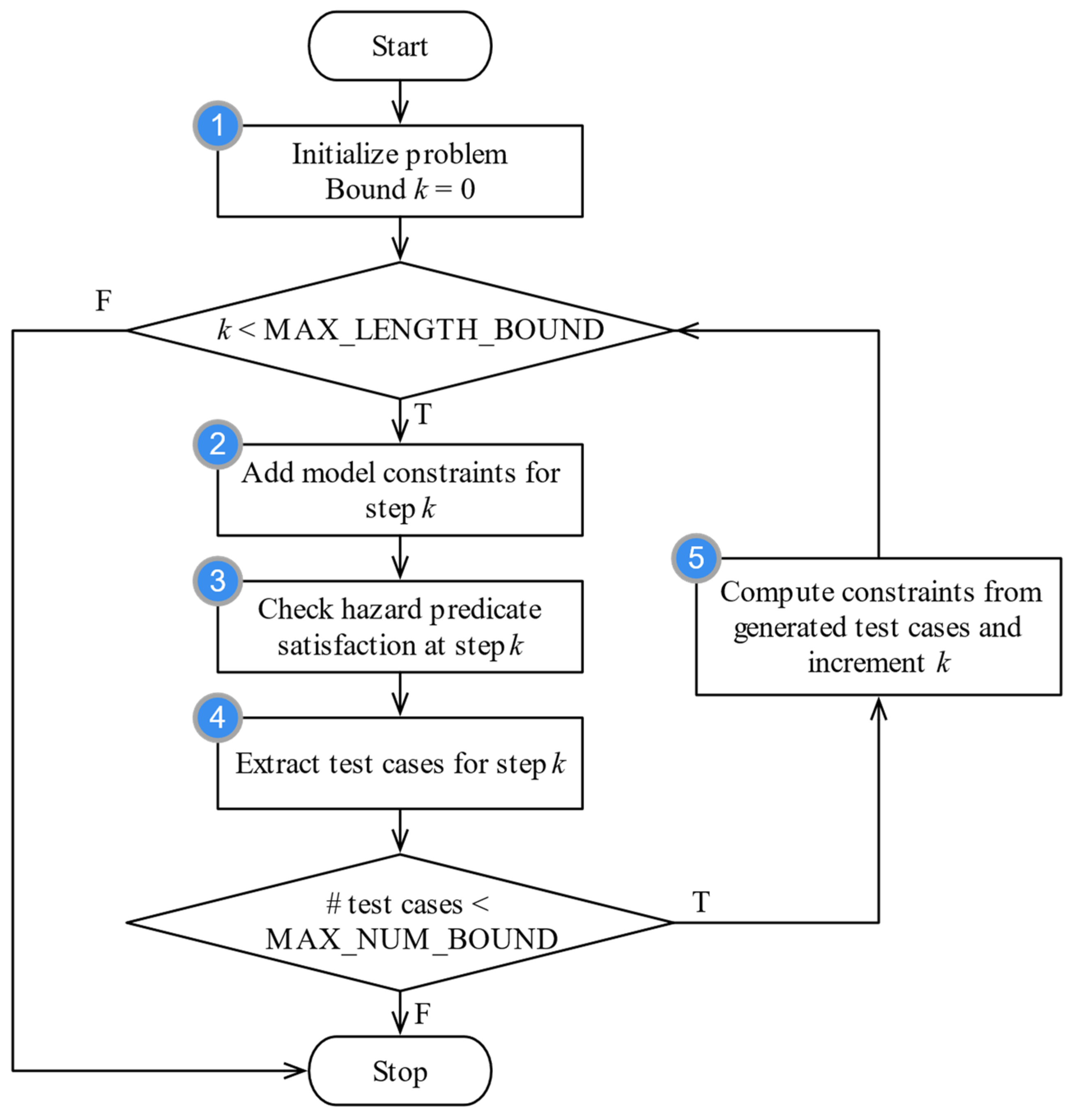
The detailed design of the low-abstraction-level algorithm is shown in
Figure 2. The time complexity of this algorithm is O(n). The details of this algorithm can be summarized as the following steps:
Step 1: During the initialization phase, the input model is processed, and auxiliary variables and constraints are synthesized to enable the successive test generation phase.
Loop: It iterates through step 2 to step 5 until the exit condition is met.
Step 2: Add permanently to the search problem the constraints imposed by the model for the current bound.
Step 3: Check for the satisfaction of the hazard predicate considering the input model and the additional constraints.
Step 4: In case the search has been successful, extract the found test cases and store them.
Step 5: If the maximum number of desired test cases is not reached, compute additional constraints to efficiently exclude the generated test cases for the successive searches.
Exit: If the maximum number of desired test cases is reached, exit.
At the end of the ATG execution, if the hazardous condition can be verified within the maximum length bound, a test suite is generated that takes into account the constraints of the model.
4. The Concept Alignment Example Setup and Modeling
The emergency response (ER) SoS is a frequently investigated scenario in the SoS context. Therefore, we established a simplified ER SoS as the concept alignment example (CAE) to ensure all parties in this research were working under the same concept. In this paper, we used this CAE as the experimental environment to illustrate the use of our proposed ATG method. This section describes the CAE design model, which covers the modeling in detail as well as the setup and provides an overview of the algorithmic aspect of the ATG process.
4.1. Experimental Setup
Figure 3 represents an overview of the test generation activities flow, which can be summarized as follows:
The SoS was captured as a UPDM model including the description of the CSs, their interfaces, and the connections between them. For each interface/connection the relevant events exchanged were identified.
For each system, the model was detailed with the possible faults that could occur, and how the occurrence of a fault affected its functionality was also formalized.
A set of SoS hazard conditions was then identified and modeled. The hazard conditions represented unsafe behaviors that the SoS should not expose and were used by the ATG tool to identify interesting test cases.
The enhanced UPDM model was then processed by the ATG tool and a set of test suites was produced.
The CAE was an emergency response (ER) SoS and the CAE model allowed the exploration of different approaches to the modeling of the different aspects of an ER SoS. In this section, we outline a simplified CAE model to show the limitations and concrete applicability of the ATG process, which we use as a running example in the next section.
The CAE model for ATG (CAE-ATG) was developed as a UPDM model in IBM Rational Rhapsody, and
Figure 4 provides a top-level view of the system, representing the system’s interface description (SV-1) view.
The CAE-ATG was composed of three CSs, namely the district, the fire station, and the firefighting machine. Each CS was modeled as a SystemNode that communicated with the others using Services that exchanged events. Each event may represent:
An accidental hazardous condition that the SoS should control to avoid losses such as the occurrence of a fire in the district (event heOnFire of the district block);
A communication/action between blocks in order to safely control the hazardous event (events evOnFire of fire station or evEst of district);
The occurrence of a fault that degrades the capability of a CS to properly handle or control hazardous events such as evCarFailure of the firefighting machine block.
For each block, the set of ports and the events exchanged by each port were defined as well as the connection to other blocks. The objective of the SoS control was to avoid the occurrence of hazardous conditions as a consequence of CS misbehavior or unexpected interactions. For the CAE-ATG, it was possible to define several hazards, and for the simplified case in the analysis used for this experiment, we focused only on one specific hazard, which was expressed as “every time the district is on fire, the fire is not extinguished in a finite amount of time”. This condition identified a set of undesirable SoS behaviors for which the safety control loop could not react to the detection of a district fire. The following is a brief description of each CS, focusing on the system requirements for controlling fire events.
District: It represents an urban area under the control of a fire station and subject to the occurrence of a fire accident. In case of fire, it is expected that the fire is signaled from the district to the corresponding fire station, and it is considered extinguished if at least one firefighting machine is dispatched to the district and successfully executes its task.
Fire station: it has the responsibility of collecting the alarm signals from the district and dispatching as soon as possible a firefighting machine to extinguish the fire. It is the responsibility of the district to keep track of the dispatched machines.
Firefighting machine: it has the responsibility of receiving a command from the fire station, to move to the district, and to extinguish the fire. Once the fire has been extinguished, the machine returns to the fire station and can receive another command. If the machine is in “operative” mode (i.e., it has been dispatched to the district), it cannot receive other commands.
4.2. SoS Modeling for ATG
The modeling of the SoS for the fault-based ATG was similar to the one defined for the simulation analysis. In order to allow the tool to automatically search for test cases, the SoS model should be set up to include elements capturing some analysis-specific concepts such as the fault or accident events.
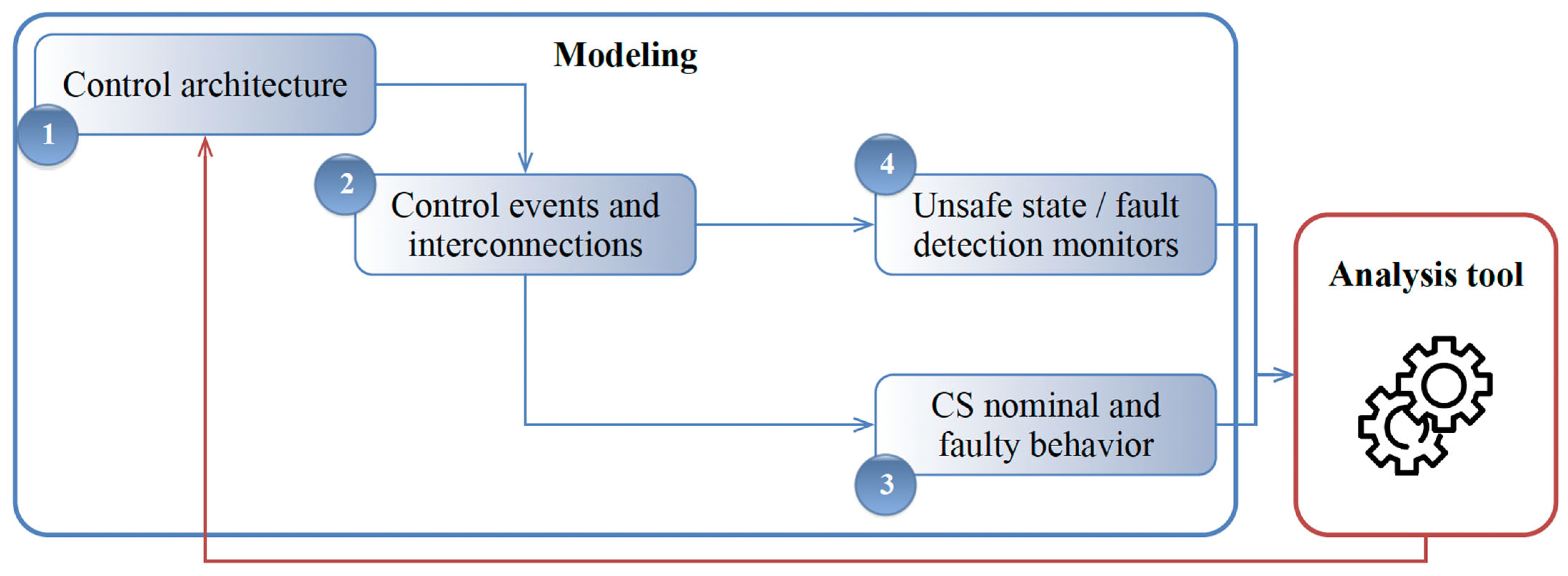
Figure 5 summarizes the main modeling activities and artifacts required for the successful execution of the ATG process. The modeling flow was as follows:
Control architecture identification: The SoS architecture was modeled in terms of CSs and messages exchanged. For each system, an internal decomposition could be performed to better identify the responsibilities of safety control at lower hierarchical levels.
Control events and interconnection definition: For each system, the subset of received and sent events relevant to the safety of the SoS was identified. These events represented the messages and control actions that were needed to coordinate the CS in order to mitigate the effects of a dangerous event.
System’s behavior: The nominal behavior of each system was modeled by describing how it reacted to hazardous events or other systems interactions. The modeled behavior represented an abstraction of the behavior of the CS. For each system, the possible faults were identified and the behavior of the system in their presence was captured (error model). The system’s behavior may contain or not a description of the fault detection, identification, and recovery mechanisms.
Unsafe state or fault detection monitors: The hazard conditions representing unsafe states that may lead to accidents and losses were identified in case a scenario-based generation (or scenario-based ATG) had to be performed. In case a fault injection for fault detection had to be performed, the detection mechanisms were modeled.
4.3. CAE-ATG Control Events and Interconnection Model
The CAE-ATG SoS architecture is omitted due to the page limit. In this subsection, we detail the events that each block can send and receive and the modeled interconnections between blocks.
4.3.1. District CS Block
The district communicates with the fire station to signal the presence of a fire and with the firefighting machines. The CS communicates using two interaction points. Port
pFS allows the interaction with the fire station block; port
ffm allows events to be received from the firefighting machines. The details of the exchanged events are summarized in
Table 1.
The presence of a fire was modeled using a specific event (heOnFire) modeling both the presence of a fire and the occurrence of an accident causing it. From a modeling point of view, it is an “external” event, and it is not associated with any source block (it represents the “random” occurrence of the emergency accident, and it can be seen as an “uncontrolled input” of the CS). The other events (evOnFire and evEst) are exchanged as part of the control algorithm of the fire event: once the fire has been detected, the district sends evOnFire to the fire station to signal it and if the SoS control is effective, it receives an evEst event in a finite amount of time.
4.3.2. Fire Station CS block
The fire station communicates with the environment with two ports. Port
pDistrict encapsulates the interactions with the district; port
ffm with multiplicity 3 allows the dispatch of the commands from the district to the three firefighting machines. The exchanged events are summarized in
Table 2.
Events evOnFire, evGo, and evCarReturned model the messages exchanged by the fire station as part of the control loop. Events faComm and restoreComm model the presence of faults. The failure of communication (faComm) is a “random” transient fault that affects the capability of the fire station to effectively respond to an alarm: when present, the system moves to a “degraded” mode in which all the communications are disabled. The fire station returns to the normal state when the restore event (restoreComm) happens.
4.3.3. Fire Fighting Machine CS block
The CAE-ATG model contains three firefighting machines per district. Each machine receives a dispatch command from the district (
evGo) and if the fire is extinguished (
evEst), returns back to the fire station (
evCarReturned). Each machine is subject to a fault that completely inhibits its usage in case of fire (
evCarFailure) until the car is restored (
evCarFailureRestore). The details of the exchanged events are summarized in
Table 3.
4.4. CAE-ATG Systems Behavior Specification
For each system of the CAE-ATG, the behavior was specified in terms of a state machine using the SV10b (systems state transition description UPDM diagram). Each state machine formalized the nominal behavior of the system in presence of events (hazardous, request/send, fault, and recovery). The transitions of the state machines were triggered by events and may be guarded by conditions on the system resources (modeled as integer attributes of the SystemPart UPDM block). The actions consisted of the emission of events or elaboration of the attributes. The following sections are detailed descriptions of each CS’s behaviors.
4.4.1. District CS Behavior
As
Figure 6a shows, the behavior of the district modelled the requests of a firefighting machine (
evOnFire) as soon as a fire hazardous event (
heOnFire) occurred. The system switched back to a normal state of operation (state NOMINAL) as soon as a fire extinguishing event (
evEst) was received.
4.4.2. Firefighting Machine CS Behavior
The firefighting machine’s modal behavior is depicted in
Figure 6b. The car starts in an
IDLE state and when an
evGo event occurs, it moves first to a
MOVING state and then to a
WORKING state. After the fire has been successfully extinguished (transition from
WORKING to
REPORTING state) it moves back to the fire station and reports its presence to the district. Each firefighting machine is subject to a fault event (
evCarFailure) that inhibits the normal operative mode of the car until a corresponding restore event (
evCarFailureRestore) happens.
4.4.3. Fire Station CS Behavior
In normal mode, the fire station system dispatches a firefighting machine to the district every time it is requested (
evOnFire received) and there is at least one car available. In case a communication failure (event
faComm) is present, the system transitions to the COMM_FAILURE state, in which it does not react to external requests and cannot dispatch machines until a restore event happens (
restoreComm).
Figure 7 is the SV-10b diagram for fire station.
4.5. CAE-ATG SoS Hazard Conditions
For experimental purposes, a hazardous condition regarding the ability to respond to fire events was set for the CAE SoS. In order to enable the ATG process, a proper formalization of the condition using the GCSL was needed, which is presented below.
Whenever [evOnFire] occurs, [evEst] does not occur within [range].
It is a derivation of the existing pattern “Whenever [p1] occurs [p2] does not occur during following [a, b]”.
The property models a specific bound in terms of the number of steps within the SoS that must react to a fire event. This bound is considered “sufficiently” large to impose a correct safety constraint on the SoS: in case a reaction of the system does not occur within the specified bound, the fire is considered to cause severe damage to the district. The tool imposes some constraints on the possible formalization of the SoS hazards that can be only a safety property. More precisely, a hazard should be modeled as a Boolean function that is FALSE if the hazard does not occur and TRUE if the hazard occurs.
5. Experimental Results
The ATG execution process is responsible for identifying the hazardous chains of events leading to the verification of an ATG condition that might be the reachability of an unsafe state or the enabling of a fault detection mechanism. Each event chain represents a test case that can be used to reason on the model. The whole process implemented from a technical point of view in the experiment to enable the ATG can be summarized as follows.
The designer produces the UPDM model of the SoS following the guidelines in
Section 4.
The model is checked by a model validation component. Only a subset of the UPDM language is supported by the ATG engine and the main purpose of the validation is to verify the compliance of the input model with the supported features. This is to avoid the execution of time-consuming successive steps by catching unsupported elements as soon as possible. In case the validation fails, an error report is produced, and the translation is aborted.
When the model is compliant with the ATG restrictions, the simulation is invoked to generate the test cases. In particular, the following steps are performed: (i) the model is processed using a model-to-model transformation that produces a semantically equivalent model; (ii) the generated model is processed as a formal problem for the verification to enable the ATG execution; and (iii) the ATG execution is effectively performed, and a set of test cases is produced as well as a test generation report.
As an example, we simulated the application of the scenario generation analysis to the CAE-ATG model. The ATG process intuitively looked for possible fault events injections that led to the verification of the hazard, which in this case was the absence of the evEst event within five model execution steps after the occurrence of a fire event. For each generation loop in the algorithm, a MCS was produced according to input models as the minimal operations and states for the top-level events. Then, the MSC was used in conjunction with error constraints in the system-level design to inject faults for a test case.
In this experiment, multiple scenarios were generated as test cases under different settings of the ATG algorithm parameters. Some generated scenarios are represented in
Table 4. For conciseness, only the relevant events are represented in the table and only the change of value is marked after the ATG.
The three test cases identified different evolutions of the SoS leading to the hazard condition. The three scenarios were representative of three distinct “families” of unsafe behaviors exposed by this simplified CAE SoS.
Scenario SC-01 identified the presence of a car failure event evCarFailure as a cause of hazard due to the design of the fire district control mechanism that did not take into account the possibility that a car fails during the dispatching and could send a dispatch event to a car without any check on its availability. The state-machine description of the fire station reacted to the alarm dispatching the car; however, as captured by the test case, if at the same time the car was in a failure state it could not receive the dispatch command; hence, it was not capable of extinguishing the fire. This test case exposed a problem related to the fire district design. This may be due to the simplified abstraction or to a design error.
Scenario SC-02 showed how the occurrence of a communication fault event in the fire district led to the verification of the accident. This scenario exposed a possible fault tolerance issue with the SoS, i.e., all the communications were handled by the fire district. In this case, a redundant communication mechanism inside the fire district was needed to handle possible communication errors properly, without affecting the safety of the entire SoS.
Scenario SC-03 identified a test case where, due to the limited number of vehicles, the SoS was not capable of successfully tackling a fire event if more than three fire events were previously detected. This test case exposed an inherent structural limitation of the SoS due to the limited number of resources available, which was an unsafe behavior emerging after the CSs were integrated to the SoS.
Many other cases are possible due to the asynchronous communication of the different systems within the SoS. As already mentioned in previous sections, it is fundamental to impose constraints on the admissible occurrences of failure and hazard events in order to focus only on meaningful scenarios.
6. Conclusions
To enhance the capability of SoS model verification and improve the robustness of SoS architecture design, we proposed an ATG method for an SoS with fault injection and model-based systems engineering as the foundations. An SoS was modeled as a UPDM artifact that contained formal models of accident events, fault occurrences, and hazardous states. The hazardous behaviors could be caused by three types of issues, including single design flaws within a single CS model or interactions between CSs, combinations of multiple flaws within a CS model, and the emergence of dangerous behaviors after the CSs were integrated into the SoS. It is the responsibility of the ATG to generate a set of meaningful test cases identifying such unsafe emergent behaviors and it is fundamental to impose assumptions on the occurrence of the events in order to derive meaningful test cases.
The proposed ATG method involved both modeling and analysis activities, consisting of a two-phase ATG approach and a test generation algorithm. The first phase of the designed ATG approach was modeling, which produced UPDM models with faults’ description, behaviors’ effects, and FDI mechanisms. The second phase of the designed ATG approach was generation, which covered three envisioned generation scenarios, and an algorithm supported the test generation activity by deriving the fault injections that enabled the FDI process. This method was dedicated to automatically identify some input trajectories as test cases for design verification; specifically, the test cases were used to detect hazardous behaviors in CSs and SoS models.
In order to show the applicability of the proposed method, a specific embodiment of the CAE use case, a simplified ER SoS, was described. By generating three scenarios as the test cases exposing different hazardous behaviors in this CAE SoS model, we demonstrated the feasibility of the ATG method proposed in this paper. Compared with a manual test case analysis and design, the proposed method improved the work efficiency. More importantly, our ATG method provided the ability to detect hazardous states in SoS design verification.
More work is still required to refine the method to support constraints’ adjustment for complex SoS models. In the current process, FDI mechanisms and SoS constraints are manually specified in the relevant models through the modeling phase. Our further research work will mainly focus on designing fault injection constraints as parameters and upgrading the designed ATG algorithm and approach to support tuning constraints’ parameters. In addition, specific ATG methods and applications for different categories of SoS and modified ATG for more system languages are follow-up research directions that need more effort.


