Article

Experimental Study on Improvement Mechanism of Electric Heating-Assisted Cyclic Steam Stimulation of Horizontal Well

1
School of Energy Resources, China University of Geosciences, Beijing 100083, China
2
Research Institute of Petroleum Exploration and Development, PetroChina, Beijing 100083, China
3
State Key Laboratory of Enhanced Oil Recovery, PetroChina, Beijing 100083, China
*
Author to whom correspondence should be addressed.
Appl. Sci. 2022, 12(21), 11294; https://doi.org/10.3390/app122111294
Submission received: 30 September 2022 / Revised: 26 October 2022 / Accepted: 2 November 2022 / Published: 7 November 2022
(This article belongs to the Section Applied Industrial Technologies)

Abstract

:
To resolve the issues of the high porous medium flow resistance, low oil production rate, high oil decline rate, and low oil recovery factor for the cyclic steam stimulation (CSS) of horizontal wells in heavy oil reservoirs, the CSS method assisted by the electric heating (E-CSS) of horizontal wells was proposed in this study. Combining the heat from electric heating and steam during E-CSS, the analytical model of formation temperature rise was established for the three phases of electric-assisted CSS (i.e., injection, soaking, production), and physical experiments were carried out to compare the performance of conventional CSS and E-CSS. The experimental results were used to validate the analytical model and reveal the impact of the key electric heating mechanism on the horizontal CSS performance. Meanwhile, the typical well model was used to forecast the E-CSS potential. The results indicate that electric heating can achieve uniform heating in the steam injection phase, maintain heating around the wellbore in the soak phase, and reduce flow resistance and enhance oil output in the production phase. Forecasts of the typical well model indicate that electric heating can enhance the oil recovery factor by 9.4% and the oil-steam ratio from 0.14 to 0.23, implying a significant application potential in heavy oil reservoirs developed by horizontal CSS.

1. Introduction

At present, heavy oil reserves account for more than 70% of the remaining geological reserves of petroleum in the world, which are widely distributed in the United States, Venezuela, Canada, Russia and China [1,2]. The development of heavy oil is an effective measure to meet the increasing energy demand. At present, the CSS of horizontal wells has become one of the most widely used technologies to enhance oil recovery in heavy oil reservoirs. The development effect of the CSS of horizontal wells has had a significant impact on heavy oil production. However, after a long period of development, the CSS of horizontal wells is affected by factors such as high crude oil viscosity, high flow resistance in the horizontal section, and reducing energy formation. Most of the horizontal wells have problems, such as a poor utilization effect in the middle and back sections and in the low permeability sections, low oil production in the CSS cycle, rapid decline in oil production, the short effective production time in the cycle and low economic efficiency.
Non-condensate gas-assisted CSS is a common technical method, which adopts the same injection method as non-condensate gas and steam, such as N2. Due to the increase in formation pressure and the heat insulation effect of nitrogen, it can effectively increase spread effect and alleviate production decline [3,4]. In addition to the single gas auxiliary, multi-thermal fluid-assisted CSS is also an effective mining method to improve the steam stimulation effect. The multi-thermal fluid formed by various fluid components, such as steam, CO2 and N2, is effective in reducing viscosity and increasing energy, reducing steam consumption and increasing the oil-steam ratio [5,6]. However, those measures are limited to improving recovery and new technologies to improve the CSS effect need to be explored. In the past, the electric heating technology of heavy oil wells was usually used only for well heating, which has been applied in major heavy oil fields in China. Its main characteristics are low-power and low-temperature heat tracing. The power is usually 100~300 W/m and the heating temperature is about 60~90 °C. It can effectively improve the fluidity of high-viscosity oil in the wellbore and improve lifting efficiency, but it cannot improve the reservoir temperature near the wellbore area and reduce the flow resistance to the wellbore [7,8,9].
There have been some previous studies on the effects of E-CSS. Some studies indicate that electric heating reduces the viscosity near the wellbore area, increases the bottom hole pressure, and avoids the excessive release of gas near the wellbore area [10,11]. For high-temperature and high-power electric heating technology in heavy oil wells, high power electric heating rapidly heats up the reservoir, produces micro fractures, and greatly improves porous flow capacity and oil production [12,13]. Moreover, distributed electric heating can increase the average oil recovery rate by 30–50% and prolong the production cycle obviously [14]. Electric heating is feasible technologically and economically [15]. However, the previous research has mainly focused on downhole resistance heating to improve the uniform preheating effects of SAGD in the start-up phase, as well as the degree of usage of the horizontal section of SAGD and the scale of steam chamber development in the production phase [16,17,18,19,20]. Relevant research has not yet been carried out on the usage of E-CSS for the horizontal well. This paper suggests installing a high-energy, long-lasting and high-power resistance electrical heater into the horizontal section of the horizontal wells (the power is greater than 1000 W/m, the heating surface temperature reaches 300 °C, and the continuous heating time is more than 5 years), which allows for an improvement in steam enthalpy, reducing the flow resistance to wells. The use of high-temperature electric heating in the horizontal section supports promotion of the acceleration of the low-permeability sections and the middle and back sections of the horizontal wells, so as to increase production levels in the horizontal section and recovery. In this paper, the mathematical model of the E-CSS of horizontal wells was deduced and established, and physical simulation experiments for the E-CSS of horizontal wells were carried out. In addition, numerical simulation of the performance prediction for the E-CSS of horizontal wells was also conducted. The key enhance-oil-recovery mechanism of electric heating was revealed and validated. The application effects of E-CSS and conventional CSS were compared and analyzed. Moreover, the application potential of E-CSS was recognized and summarized.

2. Mathematical Model of Reservoir Heating by E-CSS in Horizontal Wells

2.1. Basic Assumptions of the Model

Due to horizontal section completion with screen liner during the CSS process, the horizontal section of the wellbore usually only goes down into the screen liner. The steam flows from the heel to the tip of the horizontal section along the screen liner, and enters the reservoir. Based on the above conditions, in order to solve and analyze the results quickly, the pipe flow and reservoir conditions for the electric heating and steam injection to heat the reservoir are made as follows:
  • There is only one resistance heating cable in the screen liner of the horizontal section of the wellbore, which is from the heel to the toe without coiled tubing;
  • The reservoir is thick enough, and the impact of cover can be ignored;
  • The thickness of the screen liner tube is negligible.

2.2. Reservoir Single Heat Source Heat Transfer Model

When any point on any cross-section of the horizontal section of an ordinary horizontal well is heated by a single heat source on the cross-section (the temperature at this point is T, the initial temperature of the reservoir is Ti, and the heat inflow speed is ϕ), the following formula can be used to represent the change in temperature T over time during the heating process of the heat source at this point [21]:
T = T i ( ϕ 4 π k ) Ei ( r 2 4 λ α t )
where Ei( x ) is an exponential integral function, and its expression is
Ei ( x ) = x e t t d t

2.3. Synergistic Heating Model of Electric Heating and Steam Injection

(1)
Horizontal well steam injection phase
Figure 1 displays the 2D cross-section map of the horizontal wellbore during steam injection. From Figure 1, in the process of steam entering into the horizontal well, on any two-dimensional slice plane perpendicular to the horizontal section of the wellbore, the steam and the electric heater are the two heat sources on the cross-section, where the heat flow rate of steam into the cross-section reservoir is ϕ s , and the heat flow rate of the electric heater into the reservoir via steam is ϕ e . According to the superposition principle of the heat source, during the steam phase of the horizontal well, the temperature rises at any point ( x ); the cross section should be equal to the heat transfer and increase of the two heat sources:
Δ T x = Δ T x s + Δ T x e
Substituting Formula (1) into Formula (2) can obtain the elevated temperature at any point x on the two-dimensional plane:
T x 1 = ( ϕ s 1 4 π k ) Ei ( r 2 4 λ α t 1 ) ( ϕ e 1 4 π k ) Ei ( r 2 4 λ α t 2 )
(2)
Horizontal well soak phase
In the horizontal well soak phase, the steam into the horizontal well is stopped; ϕ s is 0. Therefore, the temperature changes at any point x on the two-dimensional cross-section producing the sum of the temperature reduction caused by the outward diffusion of the heat and the temperature increment of the electric heating:
Δ T x 2 = T T 1 = ( ϕ d 2 4 π k ) Ei ( r 2 4 λ α t 3 ) ( ϕ e 2 4 π k ) Ei ( r 2 4 λ α t 3 )
T is the reservoir temperature at the end of the steam injection, calculated by Formula (3); ϕ d 2 is the heat diffusion rate of per unit horizontal length of this point, W/m. ϕ e 2 is the heat input rate of electric heating for the unit horizontal length of the point during the soaking phase, W/m; t 3 is the soak well time, day.
According to Fourier’s law of heat transfer, the heat transfer at any point x on the two-dimensional cross-section conforms to the radial heat transfer characteristics, and ϕ d 2 can be represented by the following formula:
ϕ d 2 = 2 π Δ T x 2 1 k l n r r w
Further transformation of Formula (6) can obtain the two-dimensional phase of the horizontal well soak phase.
φ b 2 = ( 2 π Δ T X 2 1 K l n r r w 1 4 π k ) Ei ( r 2 4 λ α t 3 ) ( φ b 2 4 π k ) Ei ( r 2 4 λ α t 3 )
Temperature changes at any point x on the cross-section can be represented by the following formula:
Δ T x 2 = ( ϕ e 2 4 π k ) Ei ( r 2 4 λ α t 3 ) 1 ( 1 2 l n r r w ) Ei ( r 2 4 λ α t 3 )
(3)
Horizontal well production phase
In the production phase of a horizontal well, as the mixed fluid of hot oil and water is extracted, because the heat of the reservoir is brought out and the continuous heat diffusion pushes outwards, the reservoir begins to cool down. However, in this process, due to the heat compensation effect of the electric heater, the cooling amplitude of the reservoir slows down, and especially the heat compensation effect in the near-well area increases significantly. According to the principle of heat superposition, the increased temperature of the reservoir at any point x on the two-dimensional plane is affected by three main control factors: the heat of the output fluid exchange, the heat of the outward diffusion of the reservoir at this point and the heat compensated by the electric heater. Formula (8) is used to represent the temperature of the reservoir at any point x on the two-dimensional plane.
Δ T x 3 = T T 2 = ( ϕ l 4 π k ) Ei ( r 2 4 λ α t 4 ) + ( ϕ d 3 4 π k ) Ei ( r 2 4 λ α t 4 ) ( ϕ e 3 4 π k ) Ei ( r 2 4 λ α t 4 )
T 2 is the reservoir temperature at the end of the soak phase, calculated by Formula (7), ϕ l is the heat transfer rate of the produced fluid per unit of horizontal section length, W/m; ϕ d 3 is the heat diffusion rate of per unit horizontal length of this point, W/m; ϕ e 3 is the heat input rate of electric heating for the unit horizontal length of the point during the production phase, W/m.
In sight of the pore space of the porous medium of the output fluid being occupied by the low-temperature fluid from peripheral reservoir, based on the temperature difference method, the point of fluid exchange and heat transfer temperature difference is expressed as follows:
ϕ l = ( q w C w + q o C o ) Δ T x 3
The heat diffusion rate per unit in horizontal length of this point is expressed by the following formula:
ϕ d 3 = 2 π Δ T x 3 1 k l n r r w
In view of the continuous change in the speed of water and oil production during the production process over time, the next time step Tn+1 is calculated iteratively according to the temperature result Tn of the previous time step:
Δ T x 3 = T T 2 = ( ϕ e 3 4 π k ) Ei ( r 2 4 λ α t 4 ) 1 [ ( ( q w C w + q 0 C 0 ) 4 π k ) ( 1 2 l n r r w ) ] Ei ( r 2 4 λ α t 4 )
Δ T x 3 ( n + 1 ) = T n + 1 T n = ( ϕ e 3 4 π k ) Ei ( r 2 4 λ α t 4 ) 1 [ ( ( q w ( n + 1 ) C w + q o ( n + 1 ) C o ) 4 π k ) ( 1 2 l n r r w ) ] Ei ( r 2 4 λ α t 4 )
The initial condition is when n = 0, Tn = T2.
According to Formulas (3), (7) and (12), combined with the thermophysical parameters of the reservoir and the operating parameters of electric heating and steam injection, the reservoir temperatures of the soak phase and the production phase can be calculated under E-CSS in horizontal well. Reservoir heating characteristics of E-CSS in horizontal well therefore can be revealed.

3. Physical Simulation Experiments for E-CSS of Horizontal Well

3.1. Materials

  • Sand: Dispersed sand from the core of FC heavy oil block after oil washing;
  • Oil: Heavy oil produced in FC block with specific gravity of 0.95;
  • Water: Simulated formation water based on the FC block water analysis data.

3.2. Experimental Equipment and Parameters

Figure 2 shows the experimental equipment of E-CSS, which mainly consists of four parts:
  • Injection system. Including two water tanks, an oil tank, two ISCO pumps and a steam generator. The ISCO pump is used to saturate the model with formation water and crude oil during the preparation process, and inject steam into the model during the experiment. Steam generator is used to produce water vapor for the experimental process;
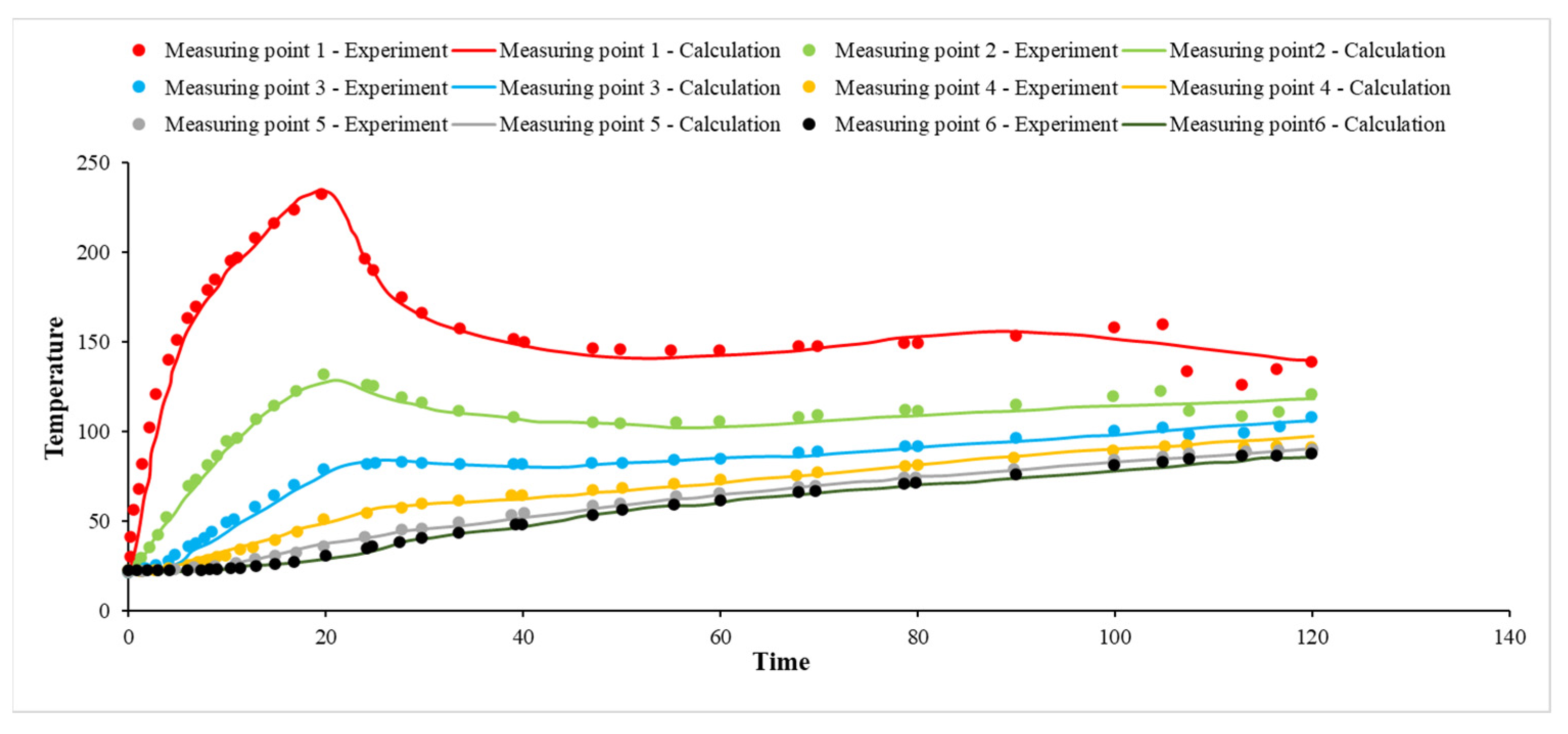
  • Model system. Including a CSS experimental model, a cylindrical horizontal well, a thermal compensation insulation sleeve, a resistance heater and 6 thermocouples. The model size is 17.8 cm × 60 cm; the horizontal well pipe is deployed in the center of the model and resistance heater is deployed on the outside of the horizontal well pipe. The thermocouple is a kind of multi-point measuring thermocouple, which five temperature sensors evenly distribute on. Moreover, 6 thermocouples with 30 sensors are evenly deployed from the center to the inner wall inside the model;
  • Electric heating control and data acquisition system. Including intelligent electric control unit for resistance heater, thermocouple temperature acquisition unit, monitoring computer, electric heating and injection data acquisition software, which is used to control the temperature of resistance heater, collect the injection data, collect model temperature and output the model temperature profile;
  • Production system. Including high-temperature back-pressure valve, output vapor–liquid automatic collector, electronic balance. High temperature back pressure valve is used to provide back pressure. Output vapor–liquid automatic collector is to collect produced fluid. In addition, electronic balance is used to measure produced fluid in real time.

3.3. Experimental Procedure

The overall experimental procedure includes these stages: sand filling, vacuum pumping, saturating formation water and oil, steam injection, soaking and production.
  • According to the particle size distribution of the reservoir sandstone, the model was filled with quartz sand with a particle size of 80~120 mesh (0.125~0.180 mm).
  • Dehydrated crude oil was injected after vacuuming and saturating the formation water to establish the irreducible water saturation and initial oil saturation.
  • After the model aged for 48 h, steam was injected at a rate of 20 mL/min.
  • After the steam injection was completed, the well was soaked for 5 min, and then opened for production.
  • The water and oil in the produced liquid were measured every 10 min. The electric heater was heated throughout the steam injection, soaking and production. The surface temperature of the heater was around 300 °C and the maximum power was 500 W.

3.4. Experimental Scheme

In order to reveal the production characteristics of E-CSS in horizontal wells and the key mechanism to improve the effect of E-CSS, the comparative experiments of conventional E-CSS in horizontal well and E-CSS in horizontal well were carried out, respectively. Each group of experiments has 4 cycles of stimulation. Parameters such as injection volume, injection rate, and soaking time are all set in the same way to ensure the same comparison conditions. The injection and production parameters are as follows: Cycle injection volume is 400 mL/min, and the steam dryness is 100%. According to the saturated steam temperature–pressure relationship, the injection steam temperature increases with the growth of the injection pressure, the temperature range is about 220 °C~270 °C, the soaking time is 5 min and the cycle production time is 100 min.

3.5. Experimental Uncertainty

Wellbore heat loss, thermal conductivity of horizontal well wall, and the difference between the model and the actual formation are all experimental uncertainties. Firstly, the thermal compensation insulation sleeve reduces the wellbore heat loss to a minimum. Secondly, since the heating resistance is placed outside the horizontal well pipe in the model, the influence range of wellbore thermal conductivity is almost negligible. Finally, the main body of the experimental model is a proportional model corresponding to the actual formation. The verification of the mathematical model of E-CSS in horizontal wells and the study of the key mechanism are fully satisfied. Therefore, the influence of experimental uncertainty on the research content of the paper is in the negligible range.

4. Experimental Results and Discussion

4.1. Verification of Mathematical Model

According to the parameters of the E-CSS experiments, the oil and water production, the temperature of the produced liquid and the experimental temperature monitoring results, the experimental verification of the analytical formula of the horizontal well E-CSS deduced before can be carried out. The comprehensive thermal conductivity of the reservoir is 2.28 W/(m·K), and the comprehensive thermal diffusivity is 0.62 × 10⁻⁶ m2/s. Figure 3 shows the comparison of the experimental and calculated temperatures for the E-CSS experiment. From Figure 3, the theoretical calculation value of the temperature at each point in the model fitted well with the experimental monitoring temperature. However, at the end of the production of E-CSS, due to the liquid production speed being about 0, the power of the electric heater over-temperature protection decreased, so the experimental temperature of measuring point one and measuring point two dropped significantly.

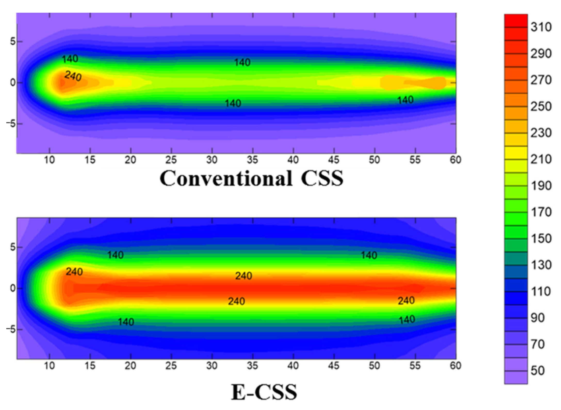
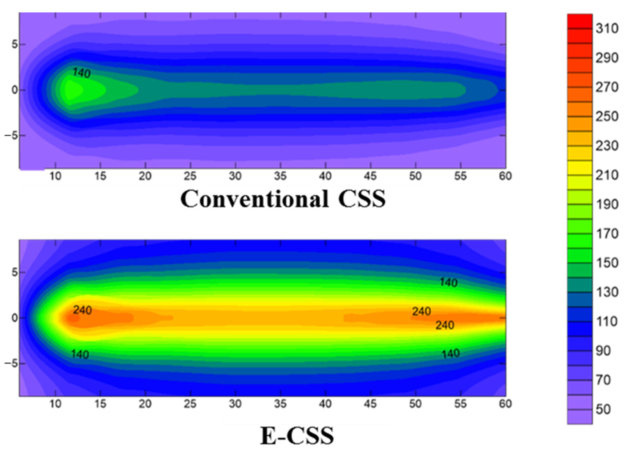
4.2. Comparative Characteristics of Temperature Field

(1)
The mechanism of electric heating in the injection phase
Figure 4 displays the temperature profile at the end of the second cycle steam injection. From Figure 4, steam preferentially entered the oil layer from the heel and toe of the horizontal well, so the temperature at both ends (average 240 °C) was significantly higher than in the middle of the horizontal well (average 210 °C) during the conventional CSS process. The isothermal heating cable along the horizontal well heated the wellbore, which significantly improved the uniformity of heating in the horizontal section and the whole horizontal well reached 240 °C in the process of E-CSS. The electric heating effectively improved the steam temperature and dryness in the wellbore and the specific heat capacity and action range of steam were expanded. The high temperature area at the end of E-CSS is obviously larger than that of conventional CSS.
(2)
The mechanism of electric heating in the soaking phase
Figure 5 displays the comparison of the temperature field at the end of the second cycle soaking phase. From Figure 5, the temperature near the wellbore area in the conventional CSS soaking phase continued to decline due to steam and thermal diffusion; and the temperature fell to an average of 140 °C. Due to the continuous heating and thermal compensation of the electric heater in the soaking stage, the temperature near the wellbore area dropped slowly in E-CSS; the temperature of the heel and toe tip of the horizontal section was continuously maintained at 240 °C, except that the middle temperature of the horizontal section dropped from 240 °C to 210 °C at the time of stopping the injection of steam. Due to the effect of thermal diffusion, the temperature from the well was also significantly higher than in the conventional CSS. The oil layer gained the continuous thermal compensation from electric heating in the soaking phase, which transferred heat to the deep part of the oil layer as well, relying on the temperature gradient.
(3)
The mechanism of electric heating in the production phase
Figure 6 displays the comparison of the temperature field at the middle of the second cycle production phase. From Figure 6, the comparison of the temperature field in the middle of production shows that, during the conventional CSS process, the temperature of the oil layer continued to decline to about 78 °C with the continuous heat diffusion of the oil layer and the heat that was taken away by the output fluid. However, the temperature of the oil layer near the wellbore area continued to be kept above 140 °C in E-CSS. This was because the continuous thermal compensation of the electric heater to the oil layer though the produced fluid drove a lot of heat away.
Figure 7 shows the comparison of the temperature field at the end of the second cycle production phase. From Figure 7, it can be seen that the continuous thermal diffusion of the conventional CSS and the output heat loss of the conventional CSS had further reduced the oil layer temperature to about 70 °C. In the second half of the E-CSS production, due to the decrease in the output fluid speed, the heat output decreased, and the continuous thermal compensation of electric heating increased the oil layer temperature; the range of temperature (140 °C) was further expanded near the wellbore area. Since the temperature near the wellbore area directly affects the flow resistance of the fluid into the well, the electric heating reduced the porous flow resistance of the crude oil into the well by increasing the reservoir temperature near the wellbore area, overall improving the oil production rate.

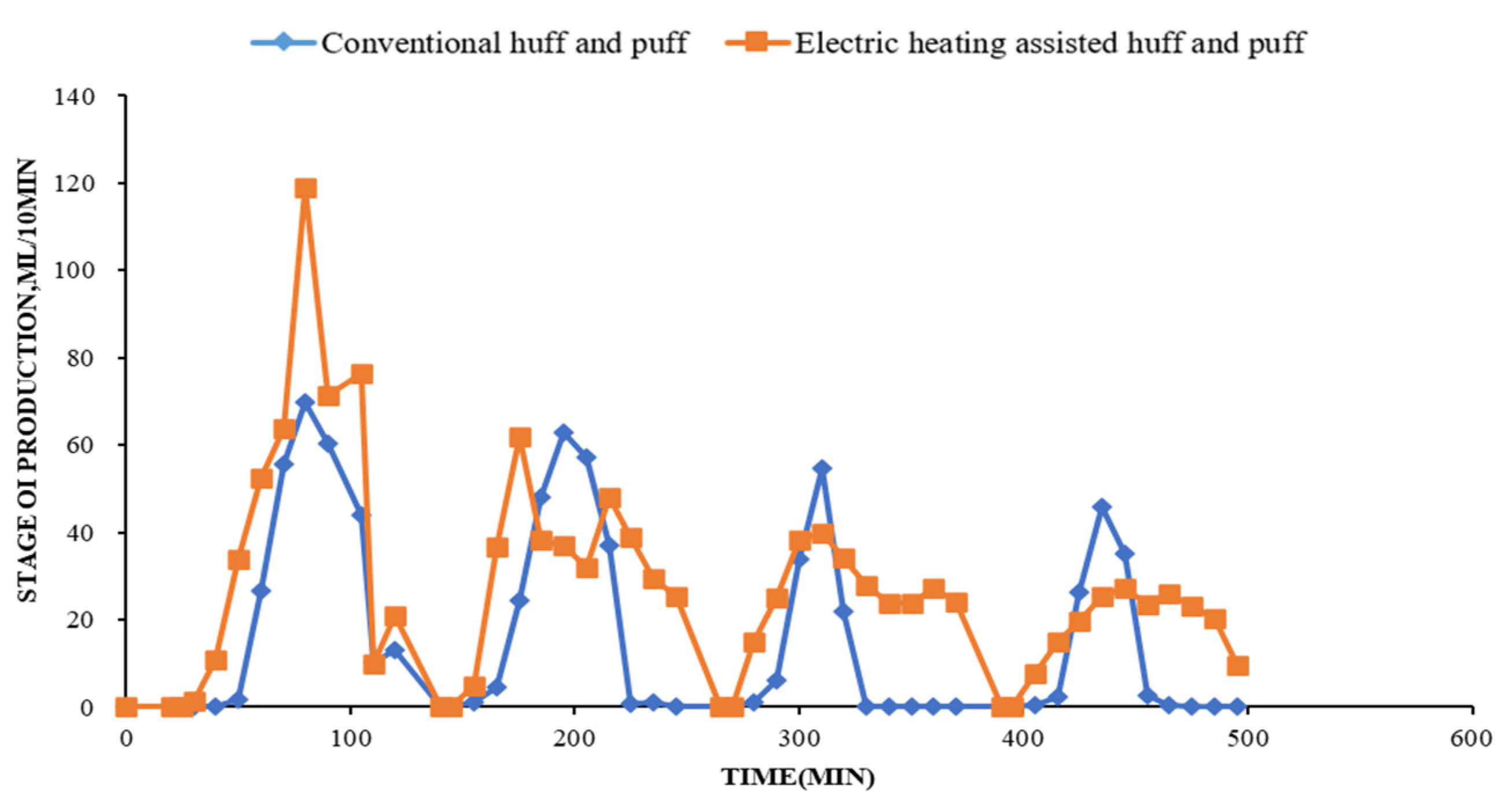
4.3. Comparison of Production Characteristics and Analysis of Porous Flow Mechanism

(1)
Comparative characteristics of conventional CSS and E-CSS
Figure 8 shows the comparison of the oil production rate for conventional CSS and E-CSS. From Figure 8, the comparison of oil production speeds shows that conventional CSS had a rapid decline in production during the production phase, while the use of electric heating effectively slowed down the decline in production. The statistics of four cycles of conventional CSS were 281 mL, 237 mL, 118 mL, 113 mL, and the total oil production was 749 mL; that of E-CSS was 460 mL, 253 mL, 280 mL, and 197 mL, a total of 1290 mL. The average cycle oil increase was more than 50% and the enhanced oil recovery effect was obvious.
During the experiment, there were certain fluctuations for production of heavy oil, and there were also certain fluctuations in the corresponding oil increase, but the overall oil increase was obvious.
(2)
The influence mechanism of electric heating on the decline rate.
For each CSS round, the effect of the heat injection on the instantaneous output at different production times in the CSS cycle can be expressed by the following formula:
1 q o ( t ) = η ρ o C o ( T s T R ) s Q t 4 + 1 q oi
η ρ o C o ( T s T R ) s Q ( t ) is the slope of the relationship curve of 1 q o ( t ) and t 4 , which is the limit on the rate of yield decline. For conventional CSS, the heat injected into the oil layer Q is the enthalpy Q s of the injected steam. For E-CSS, the heat injected into the oil layer Q is the enthalpy Q s of the injected steam and the enthalpy Q e ( t 4 ) of the electric heating input. To sum up, the decreasing rate of conventional CSS is η ρ o C o ( T s T R ) s Q s , and the decrement rate of E-CSS is η ρ o C o ( T s T R ) s Q s + Q e ( t 4 ) . Since Q e ( t 4 ) increases with time, the slope value decreases with other parameters unchanged, so the decline rate of output decreases with time. The enthalpy of steam injected into the first 1, 2, 3, 4 CSS cycles was 952,700 J, and the enthalpy of the electric heating input oil layer was 1,277,075 J, 2,899,011 J, 2,980,319 J, 2,980,250 J, respectively. Based on the calculation, the decline rate of E-CSS of the 1,2,3,4 only accounts for 42.7%, 24.7%, 24.2% and 24.2% of conventional E-CSS.
(3)
The effect of electric heating on the porous flow resistance to the well.
In the process of CSS in the horizontal well, the porous flow resistance of the fluid at any point in the horizontal section R is equal to the sum of the horizontal porous flow resistance R h , and the vertical porous flow resistance R v :
R = R h + R v = μ o ( T ) B o 2 π K h ( l n a + a 2 L 2 4 L 2 + h L l n h 2 π r w )
Since the viscosity of crude oil is a function of temperature [22],
Log ( Log ( μ o ( T ) + 0.8 ) ) = A + BLog ( T + 273.15 )
where A and B are factorless coefficients, and it is a contant value for the specific crude oil, the results of the viscosity–temperature experimental test are regressed. In this article, A of heavy oil in the target area is 9.26, and B is −3.44. Substitute the values of A and B into the Formula (15) and get it by transformation:
μ o ( T ) = 10 10 9 . 26 - 3 . 44 bLog ( T + 273.15 ) 0.8
Replace Formula (16) into (14) to obtain the flow resistance R of conventional CSS and the flow resistance R e of E-CSS.
In order to express the drop rate of porous flow resistance near the well area of E-CSS, Formula (14) is transformed:
ζ = R s R e R s = 10 10 9 . 26 - 3 . 44 Log ( T s + 273.15 ) 10 10 9 . 26 - 3 . 44 Log ( T e + 273.15 ) 10 10 9 . 26 - 3 . 44 Log ( T s + 273.15 ) 0.8
The formula above simplifies the decrease rate of porous flow resistance 5 in the near-well area of CSS to a function of temperature T . According to that formula, the graph of the decline rate of porous flow resistance in the well is calculated under different temperature conditions of the conventional CSS level horizontal section and different heating amplitude of electric heating.
Figure 9 shows the wellbore porous flow resistance reduction ratio under different electrically enhanced temperatures. From Figure 9, section and different heating amplitudes of electric heating are calculated. According to the drawing board, the lower the temperature, the higher the decrease rate of porous flow resistance by electric heating is. On the basis of 70 °C and 130 °C, the corresponding decrease rate of porous flow resistance by electric heating is increased to 52.7% and 31.1% under 10 °C, correspondingly.
The analysis above shows that, due to electric heating, the temperature of the near-well area increases in the production phase, the rate of decline of oil production over time in each CSS cycle is significantly reduced, and the flow resistance of crude oil into the well is also reduced; thus, the oil production speed and cycle production both increase.

5. Performance Prediction for E-CSS of Horizontal Well

In view of the successful application of high-power electric heating technology under foreign heavy oil wells in the oil sands of the Congo, the United States and Canada, they all have an increase in the production of heavy oil wells. Taking the actual reservoir model of A, a typical horizontal well of CSS [23,24,25,26] A in the FC well area as an example, the prediction and comparison of conventional CSS and E-CSS are carried out. The effective thickness of the oil layer corresponding to the well is 10.9 m, porosity is 32.6%, permeability is 573 mD, the viscosity of crude oil degassed at 50 °C is 20,203 mPa·s and the length of the horizontal segment is 255 m. The peak power of the electric heater is 2000 W/m, and the maximum surface heating temperature is 300 °C.
Figure 10 shows the comparison of the oil rate and oil recovery factor for CSS and E-CSS. From Figure 10, this comparison indicates that during the E-CSS process, the oil layer temperature in the near-well area continues to heat up, and the flow resistance of the horizontal section into the well is significantly reduced; the oil increase in the CSS cycle becomes more and more obvious. By the 13th round, the peak of oil increase is reached, and then gradually decreased. After the 20th round, electric heating assistance has no obvious effect. The reason is that the formation thermal field near the wellbore area in the late stage of multi-cycle CSS has been established, and there is no obvious effect in continuing electric heating to heat up the near-well area. According to the statistics, the recovery of the 20 cycles of E-CSS is 9.4%, which is higher than that of conventional CSS, and the cumulative oil–steam ratio has increased from 0.14 of conventional CSS to 0.23, indicating that electric heating can greatly increase the CSS; the oil–steam ratio and the recovery factor have important potential for improving the CSS of horizontal wells.

6. Conclusions

  • On the basis of considering the co-heating of electric heating and steam, the analytical model of reservoir heating in the three phases (steam injection, well soaking and liquid drainage) of electric heating-assisted horizontal well cyclic steam stimulation (E-CSS) is established and experimentally verified, and it can be used to predict reservoir heating in the process of electric heating-assisted horizontal well steam injection.
  • The E-CSS of horizontal wells has the key mechanisms of uniform heating and heating in horizontal sections during the steam injection phase and continuous thermal compensation heating near the wellbore area during the well-soaking phase, reducing the seepage resistance of crude oil and increasing the stimulation of production during the liquid drainage phase.
  • The E-CSS of horizontal wells can increase stimulation recovery by 9.4%, and the cumulative oil–steam ratio increases from 0.14 of conventional CSS to 0.23. Moreover, assisted electric heating can greatly increase CSS production, oil–steam ratio and oil recovery, which has important implications for improving the CSS of horizontal wells.

Author Contributions

J.Z. designed and conducted the experiments, as well as wrote the main manuscript text; Y.W. conducted numerical simulation; C.W. revised the main manuscript text; B.L. designed the experiment; Y.J. prepared all of the figures. As the corresponding author, P.L. made substantial contributions to the conception/design of the work; I agree to be accountable for all aspects of the work in ensuring that questions related to the accuracy or integrity of any part of the work are appropriately investigated. All authors have read and agreed to the published version of the manuscript.

Funding

This research was funded by the National Science Foundation of China (51774256), the China National Key Project (2016ZX05031) and the Science and Technology Project of CNPC (2021DJ3208 and 2021DJ1403).

Institutional Review Board Statement

Not applicable.

Informed Consent Statement

Not applicable.

Data Availability Statement

The data presented in this study are available from the corresponding author upon reasonable request.

Conflicts of Interest

The authors declare no conflict of interest.

References

  1. Lu, C.; Liu, H.; Zhao, W.; Lu, K.; Liu, Y.; Tian, J.; Tan, X. Experimental investigation of in-situ emulsion formation to improve viscous-oil recovery in steam-injection process assisted by viscosity reducer. SPE J. 2016, 22, 130–136. [Google Scholar] [CrossRef]
  2. Zhou, W.; Xin, C.; Chen, S. Polymer Enhanced Foam Flooding for Improving Heavy Oil Recovery in Thin Reservoirs. Energy Fuels 2020, 34, 4116–4128. [Google Scholar] [CrossRef]
  3. Tian, H. Feasibility study of nitrogen assisted steam stimulation in horizontal wells in heavy oil reservoirs of Columbia B2 well area of CAP oilfield. Pet. Geol. Eng. 2014, 28, 97–99. [Google Scholar]
  4. Yu, Y.; Liu, H.; Zhang, C.; Lei, X.; Xie, S. A study on the numerical simulation of nitrogen assisted steam injection in super heavy oil reservoir. Spec. Oil Gas Reserv. 2012, 19, 76–78. [Google Scholar]
  5. Liang, W. Action mechanism and application of multiple-thermal fluids to improve heavy oil recovery. Pet. Geol. Eng. 2014, 28, 115–117. [Google Scholar]
  6. Zhang, F.; Xu, W.; Wu, T. Research on the mechanism of multi-thermal fluids on enhanced oil recovery and reservoir adaptability. Pet. Geol. Recovery Effic. 2014, 21, 75–78. [Google Scholar]
  7. Kan, Q.; Jiang, Y.; Xu, L.; Tang, S.; Tian, J. Technology of thermal recovery of volcanic high-viscosity reservoirs in Dagang Oilfield. Oil Drill. Prod. Technol. 2009, 31, 115–117. [Google Scholar]
  8. Li, W.; Liu, P.; Yu, J.; Tao, Y. Feasibility analysis on electric heating of wellbore in heavy oilfield of Bohai. Fault-Block Oil Gas Field 2012, 19, 513–516. [Google Scholar]
  9. Liang, D.; Feng, G.; Zeng, X.; Fang, M.; He, C. Evaluation of two thermal methods in offshore heavy oilfields development. Pet. Drill. Tech. 2014, 42, 95–99. [Google Scholar]
  10. Gasbarri, S.; Diaz, A.; Guzman, M. Evaluation of electric heating on recovery factors in extra heavy oil reservoirs. In Proceedings of the SPE Heavy Oil Conference and Exhibition, Hilton, Kuwait, 12–14 December 2011. [Google Scholar]
  11. Sandberg, C.; Thomas, K.; Hale, A. Advances in Electrical Heating Technology for Heavy Oil Production. In Proceedings of the SPE Heavy Oil Conference-Canada, Calgary, AB, Canada, 10–12 June 2014. [Google Scholar]
  12. Ren, W.; Zhang, Q.; Wei, Y. Study on the oil mobility improvement by electrical heating in offshore heavy oilfields. J. Yangtze Univ. 2019, 16, 37–42. [Google Scholar]
  13. Carpenter, C. Downhole Electrical Heating for Enhanced Heavy-Oil Recovery. SPE J. 2014, 66, 132–134. [Google Scholar] [CrossRef]
  14. Lin, J.; Jiang, C.; Lu, F. Enhance Heavy Oil Production of Horizontal Well by Distributed Downhole Electrical Heating. In Proceedings of the SPE Heavy Oil Conference-Canada, Calgary, AB, Canada, 11–13 June 2013. [Google Scholar]
  15. Hascakir, B.; Babadagli, T.; Akin, S. Experimental and Numerical Simulation of Oil Recovery from Oil Shales by Electrical Heating. Energy Fuels 2008, 22, 3976–3985. [Google Scholar] [CrossRef]
  16. Hu, L.; Andy, L.H.; Tayfun, B.; Ahmadloo, M. A Semianalytical Model for Simulating Combined Electromagnetic Heating and Solvent-Assisted Gravity Drainage. SPE J. 2018, 23, 1248–1270. [Google Scholar] [CrossRef]
  17. Moini, B.; Edmunds, N. Quantifying heat requirements for SAGD startup phase: Steam injection, electrical heating. J. Can. Pet. Technol. 2013, 52, 89–94. [Google Scholar] [CrossRef]
  18. Xi, C.; Qi, Z.; Jiang, Y.; Han, W.; Shi, L.; Li, X.; Wang, H.; Zhou, Y.; Liu, T.; Du, X. Dual-horizontal wells SAGD start-up technology: From conventional steam circulation to rapid and uniform electric heating technology. In Proceedings of the SPE Symposium: Production Enhancement and Cost Optimisation, Kuala Lumpur, Malaysia, 7–8 November 2017. [Google Scholar]
  19. Zhao, R.; Yang, Z.; Wu, Y.; Zhang, R.; Luo, C.; Xi, Y. Research and application of accelerated intercommunication method in SAGD cycle pre-heating period. Oil Drill. Prod. Technol. 2015, 37, 67–69. [Google Scholar]
  20. Yang, H.; He, X.; LI, C.; Chen, S.; You, H. Advances of fast start-up technologies of SAGD process for dual horizontal wells. Xinjiang Pet. Geol. 2016, 37, 489–493. [Google Scholar]
  21. Wei, S.; Cheng, L.; Zhang, H. Analytical Solution for Double-horizontal-well SAGD Electric Preheating Model of Heavy Oil Reservoirs. J. Southwest Pet. Univ. 2016, 38, 92–98. [Google Scholar]
  22. Yu, J.; Guo, H.; Huang, X.; Chen, S.; Wang, F. The viscosive-temperature model is used to calculate technically recoverable reserves in steam huff stage of super heavy oil reservoir. Spec. Oil Gas Reserv. 2007, 14, 79–80, 104. [Google Scholar]
  23. Wadadar, S.; Islam, M. Numerical simulation of electromagnetic heating of Alaskan Tar sands using horizontal wells. J. Can. Pet. Technol. 1994, 33, 37–43. [Google Scholar] [CrossRef]
  24. Sierra, R.; Tripathy, B.; Bridges, J.E. Promising Progress in Field Application of Reservoir Electrical Heating Methods. In Proceedings of the SPE International Thermal Operations and Heavy Oil Symposium, Porlamar, Venezuela, 12–14 March 2001. [Google Scholar]
  25. Bottazzi, F.; Repetto, C.; Tita, E.; Maugeri, G. Downhole electrical heating for heavy oil enhanced recovery: A successful application in offshore Congo. In Proceedings of the International Petroleum Technology Conference, Beijing, China, 26–28 March 2013. [Google Scholar]
  26. Hale, A.; Sandberg, C.; Kovscek, A. History and Application of Resistance Electrical Heating in Downhole Oil Field Applications. In Proceedings of the SPE Western Regional & AAPG Pacific Section Meeting 2013 Joint Technical Conference, Monterey, CA, USA, 19–25 April 2013. [Google Scholar]
Figure 1. 2D cross-section map of horizontal wellbore during steam injection.
Applsci 12 11294 g001
Figure 2. The experimental equipment of E-CSS: (a) schematic figure; (b) Physical picture.
Applsci 12 11294 g002
Figure 3. Comparison of experimental and calculated temperature for E-CSS.
Applsci 12 11294 g003
Figure 4. Temperature profile at the end of the second cycle steam injection.
Applsci 12 11294 g004
Figure 5. The comparison of the temperature field at the end of the second cycle soaking phase.
Applsci 12 11294 g005
Figure 6. The comparison of the temperature field at the middle of the second cycle production phase.
Applsci 12 11294 g006
Figure 7. The comparison of the temperature field at the end of the second cycle production phase.
Applsci 12 11294 g007
Figure 8. Comparison of oil production rate for conventional CSS and E-CSS.
Applsci 12 11294 g008
Figure 9. Wellbore porous flow resistance reduction ratio under different electrically enhanced temperatures.
Applsci 12 11294 g009
Figure 10. Comparison of oil rate and oil recovery factor for conventional CSS and E-CSS.
Applsci 12 11294 g010
Publisher’s Note: MDPI stays neutral with regard to jurisdictional claims in published maps and institutional affiliations.

